


Blending textures based on our distance from them
We are now going to learn how to blend between a couple of different textures according to how far we are from the model to which they are being applied. Even though it’s great to have a complex material that works both when the camera is close to the 3D model and when we are far from it, such complexity operating on a model that only occupies a small percentage of our screens can be a bit too much. This is especially true if we can achieve the same effect with a much lower-resolution texture.
With that goal in mind, we are going to learn how to tackle those situations in the next few pages. Let’s jump right in!
Getting ready
If we look back at the previous recipe, you might remember that the semi-procedural concrete material we created made use of several nodes and textures. This serves us well to prove the point that we want to make in the next few pages: achieving a similar look using lower-resolution images and less complex graphs. We will thus start our journey with a very similar scene to what we have already used, named 02_06_Start.
Right before we start, though, know that I’ve created a new texture for you, named T_DistantConcrete_D, which we’ll be using in this recipe. The curious thing about this asset is that it’s a baked texture from the original, more complex material we used in the Creating semi-procedural materials recipe. We’ll learn how to create these simplified assets later in the book when we deal with optimization techniques.
How to do it…
Let’s jump right into the thick of it and learn how to blend between textures based on the distance between the camera and the objects to which these images are being applied:
- Let’s start by creating a new material and giving it a name. I’ve chosen M_DistanceBasedConcrete, as it roughly matches what we want to do with it. Apply it to the plane in the center of the level. This is the humble start of our journey!
- Continue by adding two Texture Sample nodes, and choose the T_Concrete_Poured_D and the T_DistantConcrete_D images as their default values.
- Next, include a Texture Coordinate node and plug it into the first of the two Texture Sample nodes. Assign a value of 20 to its two parameters, U Tiling and V Tiling.
- Place a Lerp node in the graph and connect its A and B input pins to the previous Texture Sample nodes. This is how the graph should look up to this point:
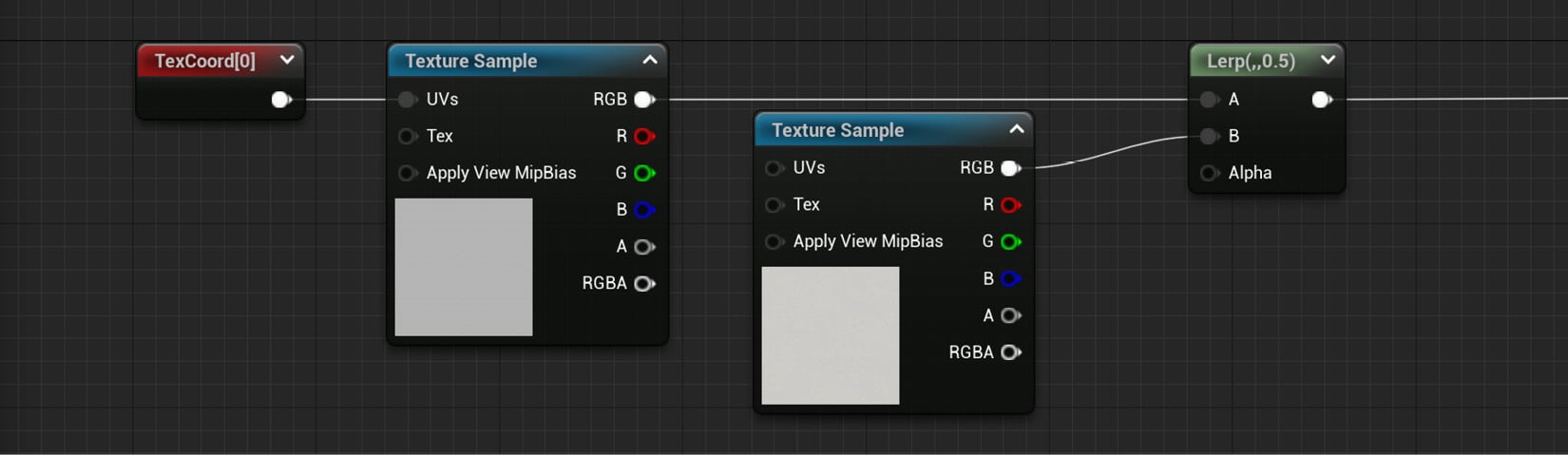
Figure 2.29 – The material graph so far
Everything we’ve done so far was mixing two textures, one of which we already used in the previous recipe. The idea is to create something very similar to what we previously had, but more efficient. The part that we are now going to tackle is distance-based calculations, as we’ll see next.
- Start by creating a World Position node, something that can be done by right-clicking anywhere within the material graph and typing its name. This new node allows us to access the world coordinates of the model to which the material is being applied, enabling us to create interesting effects such as tiling textures without considering the UVs of a model.
Important note
The World Position node can have several prefixes (Absolute, Camera Relative…) based on the mode we specify for it in the Details panel. We want to be working with its default value—the Absolute one.
- Create a Camera Position node. Even though that’s the name that appears in the visual representation of that function, the name that will show up when you look for it will be Camera Position WS (WS meaning World Space).
- Include a Distance node after the previous two, which will give us the value of the separation between the camera and the object that has this material applied to it. You can find this node under the Utility section. Connect the Absolute World Position node to its A input pin, and the Camera Position one to the B input.
- Next, add a Divide node and a Constant node. You can find the first node by just typing that name, or alternatively by holding down the D key on your keyboard and clicking in an empty space of the material graph. Incidentally, Divide is a new node that allows us to perform that mathematical operation on the two inputs that we need to provide it with.
- Give the Constant node a value of something such as 256. This will drive the distance from the camera at which the swapping of the textures will happen. Higher numbers mean that it will be further from the camera, but this is something that has to be interactively tested to narrow down the precise sweet spot at which you want the transition to happen.
- Add a Power node after the previous Divide node and connect the result of the latter to the Base input pin of the former. Just as with the Divide node, this function performs the homonymous mathematical operation according to the values that we provide it with.
- Create another Constant node, which we’ll use to feed the Exp pin of the Power node. The higher the number, the softer the transition between the two textures. Sensible numbers can be anything between 1 to 10 – I’ve chosen 4 this time.
- Include a Clamp node into the mix at the end, right after the final Power node, and connect both. Leave the values at their default, with 0 as the minimum and 1 as the maximum.
- Connect the output pin of the previous Clamp node to the Lerp node that we used to blend between the two textures acting as the Base Color node, the one we created in step 4.
The graph we’ve created should now look something like this:
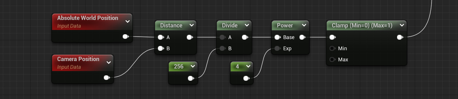
Figure 2.30 – The logic behind the distance-blending technique used in this material
We should now have a material that can effectively blend between two different assets according to the distance at which the model is from the camera. Of course, this approach could be expanded upon and made so that we are not just blending between two textures, but between as many as we want. However, one of the benefits of using this technique is to reduce the rendering cost of materials that were previously too expensive to render—so, leaving things relatively simple will help work in our favor this time.
Let me leave you with a screenshot that highlights the results both when the camera is up close and when it is far away from our level’s main ground plane:
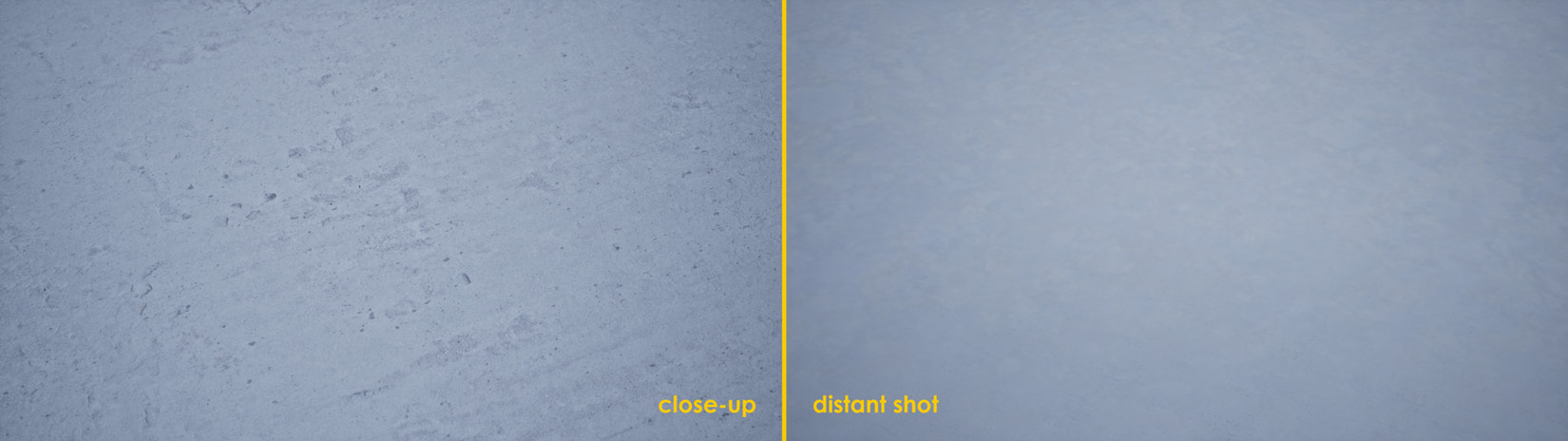
Figure 2.31 – Comparison shots between the close-up and distant versions of the material
As you can see, the differences aren’t that big, but we are using fewer textures in the new material compared to the previous one. That’s a win right there!
Tip
Try to play around with the textures used for the base color and the distance values used in the Constant node created in steps 8 and 9 to see how the effect changes. Using bright colors will help highlight what we are doing, so give that a go in case you have trouble visualizing the effect!
How it works…
We can say that we’ve worked with a few new nodes in this recipe—Absolute World Position, Distance, Camera Position, Divide, Power, Clamp… We did go over all of them a few pages ago, but it’s now time to delve a little bit deeper into how they operate.
The first one we saw, the Absolute World Position node, gives us the location of the vertices we are looking at in world space. Pairing it with the Camera Position and Distance nodes we used immediately after allowed us to know the distance between our eyes and the object onto which we applied the material—the former giving us the value for the camera location and the latter being used to compare the positional values we have.
We divided the result of the Distance node by a Constant using the Divide node, a mathematical function similar to the Multiply node that we’ve already seen. We did this in order to adjust the result we got out of the Distance node—to have a value that was easier to work with.
We then used the Power node to drive the mathematical operation, which allowed us to create a softer transition between the two textures that we were trying to blend. In essence, the Power node simply executes said operation with the data that we provide it. Finally, the Clamp node took the value we fed to it and made sure that it was contained within the 0 to 1 range that we specified for it—so, any higher values than the unit would have been reduced to one, while lower values than zero would have been increased to zero.
All the previous operations are mathematical in nature, and even though there are not that many nodes involved, it would be nice if there were a way for us to visualize the values of those operations. That would be helpful with regard to knowing the values that we should use—you can imagine that I didn’t just get the values that we used in this recipe out of thin air, but rather after careful consideration.
There are some extra nodes that can be helpful in that regard, all grouped within the Debug category. Elements such as DebugScalarValues, DebugFloat2Values, and others will help you visualize the values being computed in different parts of the graph. To use them, simply connect them to the part of the graph that you want to analyze and wire their output to the Base Color input pin node of the material. Here is an example of using the DebugScalarValues node at the end of the distance blend section of the material we’ve worked on in this recipe:
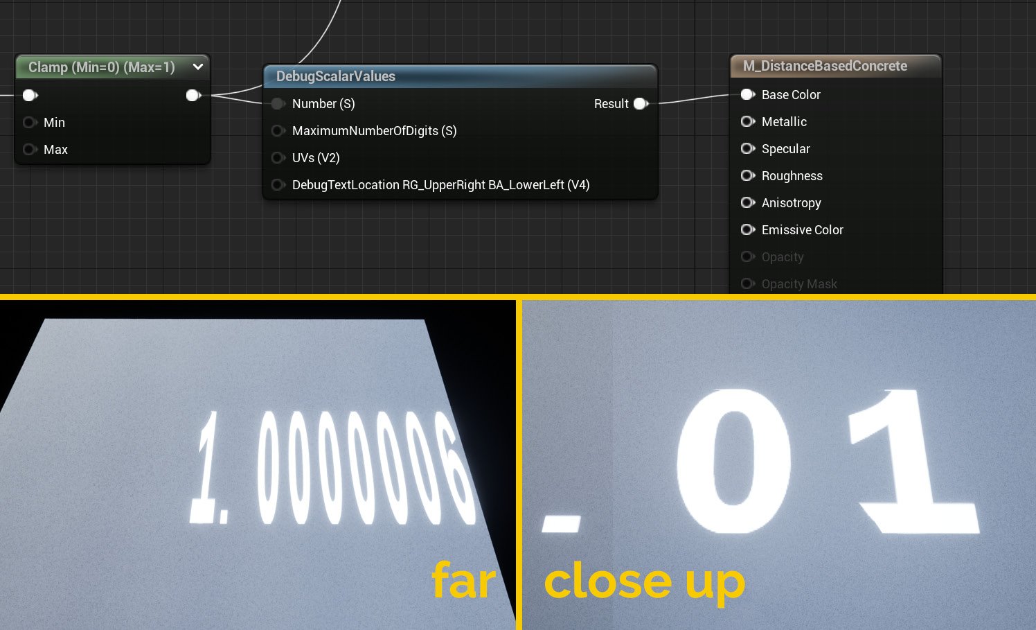
Figure 2.32 – The effects of using debug nodes to visualize parts of the graph
See also
You can find extra information about some of the nodes we’ve used, such as Absolute World Position, in Epic Games’ official documentation:
https://docs.unrealengine.com/en-US/Engine/Rendering/Materials/ExpressionReference/Coordinates
There are some extra nodes in there that might catch your eye, so make sure to check them out!