

What is Raspberry Pi Pico, and why is it suitable for robotics?
At the heart of every robot is a controller. Usually, this is a computing device that is responsible for running the code for the robot to perform its tasks and behaviors. Choosing a controller is a key choice in robot design. You can either come from the I have this controller, what can I do with it? perspective or the which controllers have the capabilities I’ll want for a particular robot? perspective.
In this section, we’ll take a closer look at what Raspberry Pi Pico offers as a controller and the trade-offs it’s made. We’ll explore why it is good for robotics and why it could be part of a larger, more interesting system, too.
Additionally, we’ll delve into the details of its interfaces and how they’ll be useful to us.
A microcontroller that runs Python
Let’s start by taking a look at Raspberry Pi Pico, and discover what it has. The following photograph shows Raspberry Pi Pico:
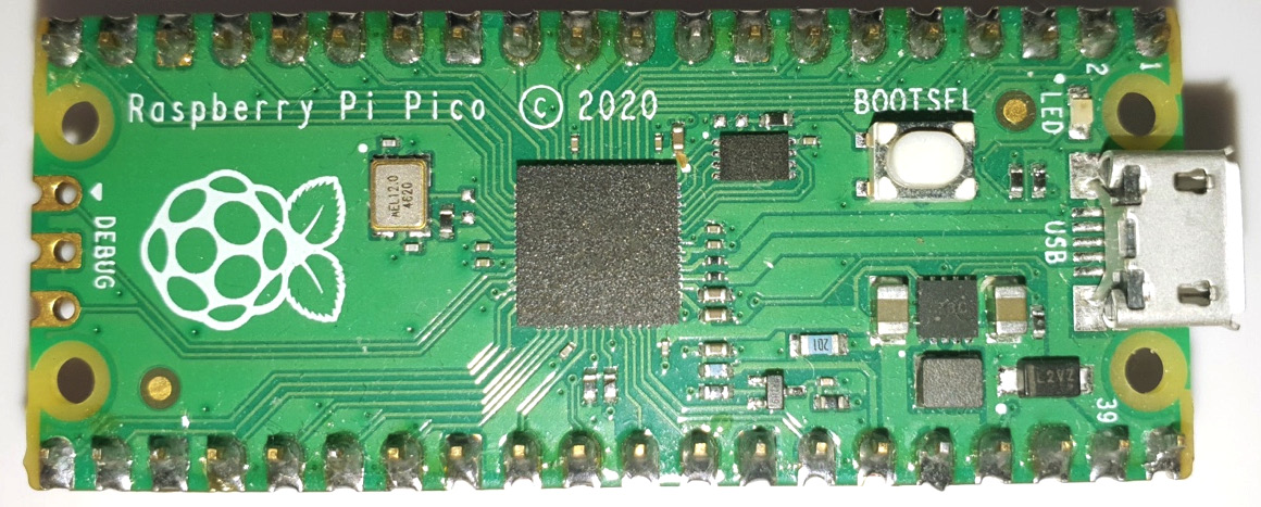
Figure 1.1 – Raspberry Pi Pico
Raspberry Pi Pico, as shown in Figure 1.1, is an RP2040 microcontroller on a Raspberry Pi-designed board. This microcontroller is a small computing device that has been designed to interface closely with hardware. It has a USB connection on the right-hand side for power or programming on a computer. The LED is useful for debugging. Also, there are many input/output (IO) pins around the edges to connect things. It is with these IO pins that the magic happens when it comes to controlling robots!
Controllers use IO pins to write and read from attached hardware. They can group pins into buses (which we’ll cover in more detail later) to exchange data with other devices. Additionally, they can create waveforms on outputs for controlling motors and LEDs.
This sounds a lot like the other Raspberry Pi models. However, this is a different class of computer. Raspberry Pi Pico has more in common with an Arduino board. Let’s take a closer look at what that difference means with the following diagram:
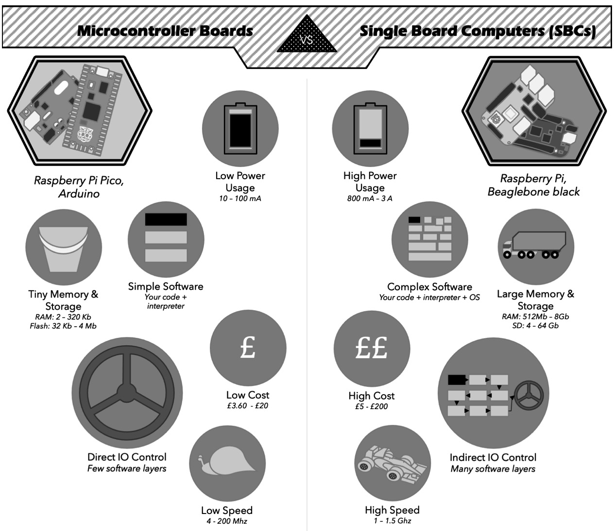
Figure 1.2 – Microcontroller boards versus single-board computers
Figure 1.2 shows that while microcontroller boards such as Raspberry Pi Pico and Arduino might look similar to single-board computers (SBCs) such as Raspberry Pi 4 or BeagleBone, they have different key areas. For instance, they differ in storage, CPU speed, cost size, the complexity of software, and how closely your software runs to the hardware.
While Raspberry Pi Pico is brilliantly suited to controlling hardware, such as robots, it isn’t as suited to high-memory or CPU tasks such as AI or visual recognition. There’s a kind of robot system known as horse-and-rider, which combines an SBC (for example, Raspberry Pi 4) for complex processing with a microcontroller (for example, Pico) for controlling hardware.
The low complexity means that code on a microcontroller has nearly no boot time, which means your code doesn’t have to coexist with other software in an operating system. Take a look at the following block diagram:
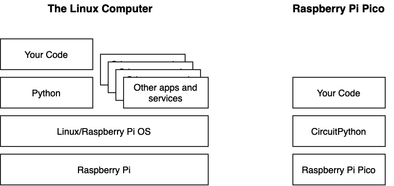
Figure 1.3 – Running your code on Raspberry Pi versus Pico
This preceding diagram represents the software architecture on Raspberry Pi versus Raspberry Pi Pico. It shows how a Linux computer, such as Raspberry Pi, has additional layers of software along with competing apps running alongside your code.
In addition to this, controllers have interrupts. They can notify the code that something has changed, such as the state of an IO pin. You’ll find this on the other Raspberry Pi models, but they are controlled by that pesky operating system again. In Pico and other microcontrollers, you get more control over what happens or when something changes on an IO pin, allowing responsive code with predictable timing.
So, how does Raspberry Pi Pico compare with the Arduino Uno? The following table shows details from their specifications and datasheets:
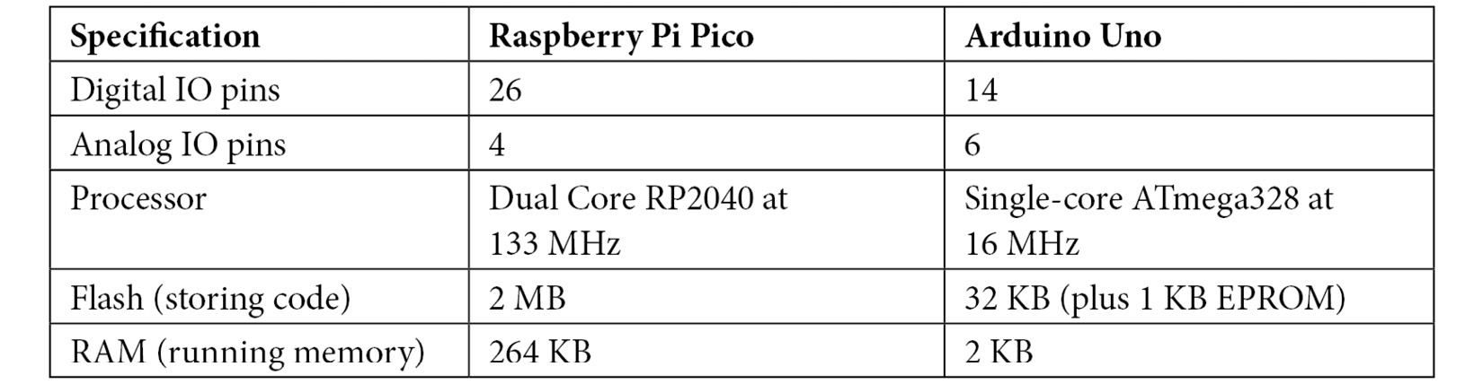
Table 1.1 – Comparing the Pico with the Arduino Uno
The preceding table shows that Raspberry Pi Pico has a faster multicore processor, along with more storage and digital IO pins. Additionally, Raspberry Pi Pico has a unique Programmable IO (PIO) system for extreme flexibility in organizing data to and from these pins. Official Pico boards are also cheaper than official Arduino boards.
Another place that Raspberry Pi Pico compares favorably with Arduino is in its use of Python (CircuitPython or MicroPython). Many microcontrollers, such as Arduino, require C/C++ to program, which can be difficult for beginners. Python is easier to understand, allows for complex and interesting data structures, and has access to many libraries of code, too.
In short, the key features of Raspberry Pi Pico are as follows:
- A microcontroller—this offers low power and is small compared with SBCs.
- It has responsible and flexible IO options.
- It is low cost compared to many microcontroller boards and most SBCs.
- It is programmable in Python.
A number of the features I attribute to Raspberry Pi Pico are due to the RP2040—the chip that powers Pico and is available in forms other than Raspberry Pi Pico.
IO flexibility is Raspberry Pi Pico’s most interesting feature, so let’s take a look at that next.
Raspberry Pi Pico’s interfaces for sensors and devices
Raspberry Pi Pico has many interfaces for connecting to hardware, along with its unique PIO system. In this section, we’ll look at each type of interface.
A digital IO pin is the basic IO system for Raspberry Pi Pico. An output can be on or off, which is great for turning LEDs on or off, but you are unable to control their brightness. Similarly, an input can also detect on or off states. Raspberry Pi Pico has 26 of these pins.
Pulse-Width Modulation (PWM) is a waveform for controlling outputs such as LEDs and motors—including DC motors, stepper motors, and servo motors. PWM pins output square wave pulses, with a changing (modulating) on-off ratio (pulse widths). Changing pulse width results in changes to the brightness of an LED, the speed of a motor, or a servo motor’s position. Raspberry Pi Pico has 16 PWM channels, making it capable of controlling many such devices at once. These PWM pins still require a power control device to drive the motors.
Analog input pins detect levels of voltage between ground (GND) and 3.3V. This is good for interfacing with simple sensors, such as light sensors, joysticks, slider/knob controls, temperature sensors, and measuring currents (using a bit of additional circuitry). Raspberry Pi Pico has three of these inputs.
A universal asynchronous receiver-transmitter (UART) controls a serial port. It can send streams of data to and from devices using two pins: a TX transmit pin and an RX receive pin. With this, it is capable of sending/receiving data that is more complicated than just a varying level. Raspberry Pi Pico has two independent UART interfaces.
Pico has two Serial Peripheral Interface (SPI) bus controllers. SPI uses four pins, as shown in the following diagram:
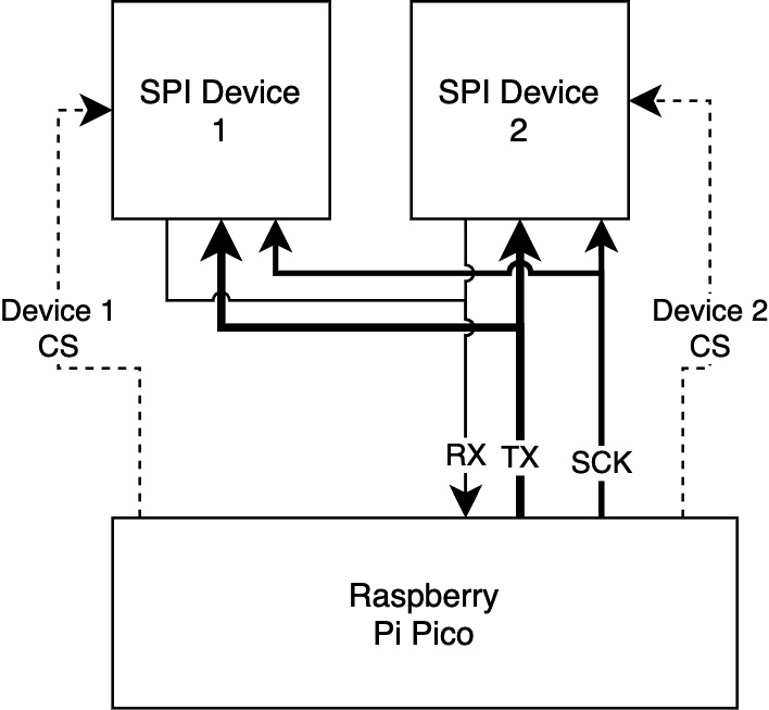
Figure 1.4 – Raspberry Pi Pico SPI bus usage
The preceding diagram shows Raspberry Pi Pico using an SPI bus to connect to two devices—for example, displays or sensors. The bus has transmit (TX), also known as Controller Out/ Peripheral In (COPI) or Microcontroller Out/Sensor In (MOSI) for transmitting data from the controller, receive (RX) also known as Controller In/ Peripheral Out (CIPO) or Microcontroller In/Sensor Out (MISO) for receiving data back to the controller, SCK (a clock for timing the signal), and Chip Select (CSEL/CS) a chip selection pin for each peripheral. SPI uses chip selections to enable communication with multiple devices, as shown by the dashed lines of Device 1 CS and Device 2 CS. See https://makezine.com/article/maker-news/mosi-miso-and-140-years-of-wrong/ for details on the current SPI acronyms.
The Inter-Integrated Circuit (I2C) is a data bus designed for communicating between integrated circuits such as sensors, memory devices, and output devices. An I2C bus has a data pin (which is often called SDA – Serial Data) and a clock pin (which is often called SCL – Serial Clock) keeping things synchronized. Multiple devices share an I2C bus by sending/receiving data with addresses, such as those in the following diagram:
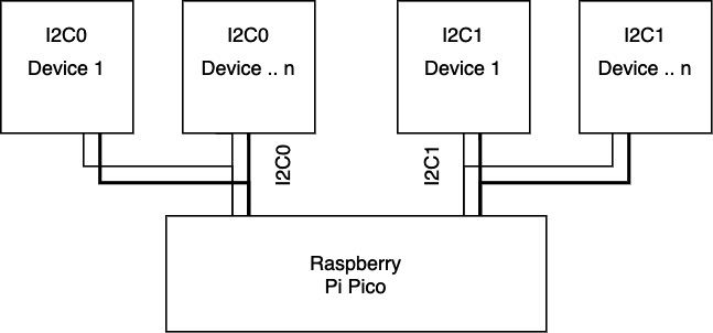
Figure 1.5 – I2C buses on Raspberry Pi Pico
Figure 1.5 shows Pico and then some child peripherals connected via two independent I2C buses, assignable to different pin configurations, with some devices having the same address but different I2C connections. Additionally, I2C can address registers (such as memory locations) within devices. We’ll use I2C later to communicate with sensors.
Finally, Raspberry Pi Pico has PIO. PIO is a feature that is unique to Pico. PIO consists of two blocks with four state machines. Each can run simple code independently of the main CPU and control one or more pins to send data to or from them. A single-state machine can control all the pins if that was useful for the code. Additionally, each state machine comes with buffers to hold data until it can be transferred. The following is an example block diagram of the PIO system:
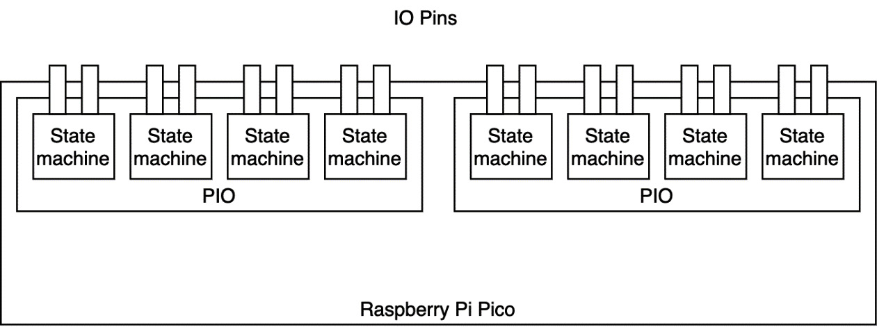
Figure 1.6 – The Raspberry Pi Pico PIO system
The preceding diagram shows two PIO devices inside the Pico. Each has code storage memory, so you can have two independent functions. In each PIO device, there are state machines that can independently run the code from that local memory.
Since PIO state machines run independently, and their instructions are about shifting data to/from pins, they can create interfaces for many kinds of hardware. For example, is there a weird protocol device? Use PIO. Do you need rapid counting independent of the main CPU? Use PIO. People have made Video Graphics Array (VGA) outputs with PIO, so it’s capable of fast and complex data handling. Additionally, you can also get interrupts from PIOs to tell you when something has happened.
That was quite a lot of IO systems. Let’s summarize them in a table, as follows:
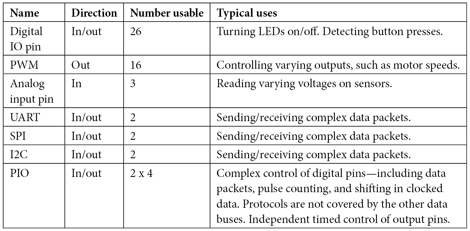
Table 1.2 – The Raspberry Pi Pico IO systems
These protocols share pins, so using an I2C bus consumes 2 pins from the 26-pin pool.
Now that we’ve had a tour of Raspberry Pi Pico’s features and interfaces, let’s take a look at how we’ll program it in this book, using CircuitPython.