


Test fitting a Raspberry Pi Pico robot
Now that we’ve checked that we can power our system, we need to make sure it is all going to fit on the robot. In this step, you get a rough idea of where things will be, whether your chassis will be big enough, and whether the robot design is likely to work.
The key thing for a test fit is that it is not detailed. Use the simplest method to check whether things will fit, be it sliding around cut-out paper rectangles or using simple software.
Let’s make some simple paper or card parts. For this section, you’ll require card, a pencil, a ruler, and scissors. Card from a cereal box is great for this, but paper will also do.
For a test fit, rectangles are often good enough. The intention is to determine what will fit inside a space and position things. Detail isn’t necessary. For large robots, you might need to make a scale model. As this robot is small, you can make parts at a 1:1 scale. This has an added advantage—if you already have parts in your possession, you get to use them.
Creating your first test-fit part
You’ll need the datasheets for your devices again—this time to start looking at the mechanical sizes of things. For a test fit, you just need to create bounding boxes for items, ensuring there is enough space for them.
Let’s start with a breadboard and the Pico. Since the Pico is on the breadboard, you can just model the breadboard size. I recommend a 400-pin breadboard, which is also known as a half-plus. Use a search engine to look for half plus breadboard dimensions and click on the images panel. What you are looking for is a flat diagram showing the outside dimensions of the board, such as the following diagram:
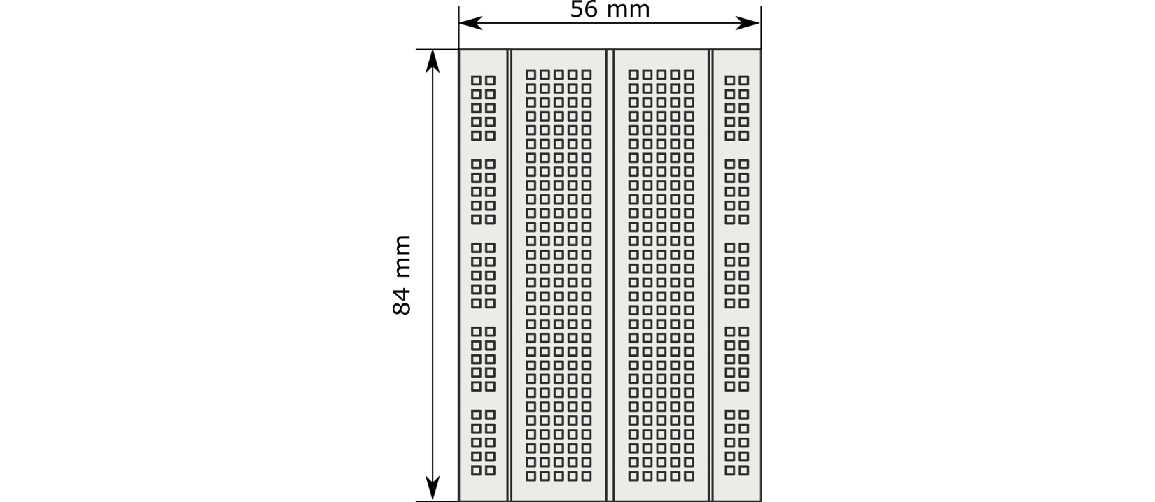
Figure 1.10 – Breadboard dimensions
The preceding diagram shows what to expect with a drawing/picture in terms of dimensions, which, in this case, is a breadboard. It measures 84 mm along the top and 56 mm along the right-hand side. It’s important to note here that I’m using millimeters throughout the book, and I will convert from other units if necessary. Stick to one measurement system in a robot design!
We can take the paper or card and draw an 84 mm by 56 mm rectangle in pencil. This does not need to be too accurate—the nearest 5 mm is good enough. The following photograph shows this:
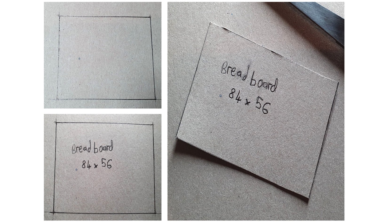
Figure 1.11 – Making a breadboard test-fit part
As the preceding photograph shows, you simply draw it out. Additionally, so that we can identify it later, write breadboard on the part, along with its dimensions of 84 x 56. Keep these handy so that they can be used for reference later.
Then, you can cut this out with scissors. I tend to make a wide rough cut, and then a finer close cut as a second pass for this.
This simple rectangle, with the right measurements, is our first test-fit part. Next, we will need the motor parts.
Motors
The motors we are using are N20 motors. If we place them on the underside of the robot, as is common with these designs, we still need to consider how their wires come up through the chassis. It is easier to put them on top so that the motor wires can face upward.
We can search the web for N20 motor brackets. Look in the images tab for drawings so that we can get the correct dimensions and add extra space for wiring behind the motor. The following photograph shows me making these test parts:
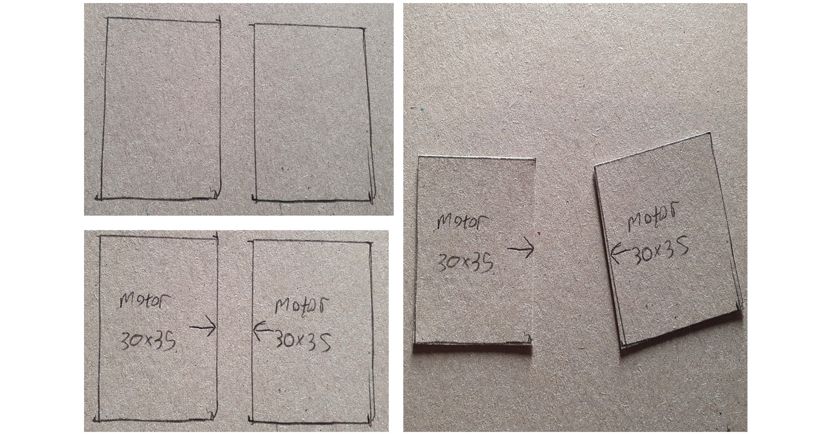
Figure 1.12 – Making cardboard motor test-fit parts
For this part, as the preceding photograph shows, we want two rectangles of 30 mm by 35 mm. Label them. On one of the longer edges of each part, add an arrow to show that this is where the wheels will go.
We have motors and a breadboard. Next, we need to make stand-in parts for powering them.
Power systems
The UBEC doesn’t take up a lot of space, so we can ignore it. The controller we’ve chosen will fit on a breadboard with the Pico, so it is already accounted for. We do need to account for the batteries.
We have a couple of variants on an 8 x AA battery holder—the flat kind, which takes up more space but comes with mounting screws, or the 4 x 2 kind. These use vertical space instead. Another way to save space is to put batteries on the underside of the chassis.
At this stage, we will use the flat holder as it is easier. You can look up the size for them and create a labeled rectangle for them. My battery box came out as 93 mm x 57 mm:
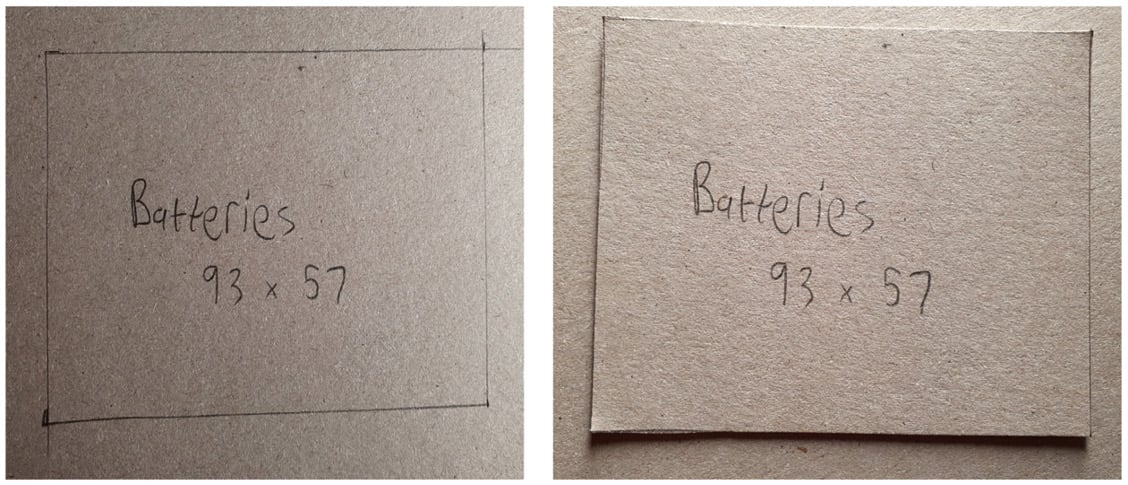
Figure 1.13 – A battery box in cardboard
The preceding photograph shows a battery box created from cardboard. Now, we have a bunch of parts to go on the chassis. Next, we need to represent the chassis itself.
Creating a rough chassis
We previously suggested that the chassis should be about 150 mm x 200 mm. Create this rectangle in cardboard, as follows:
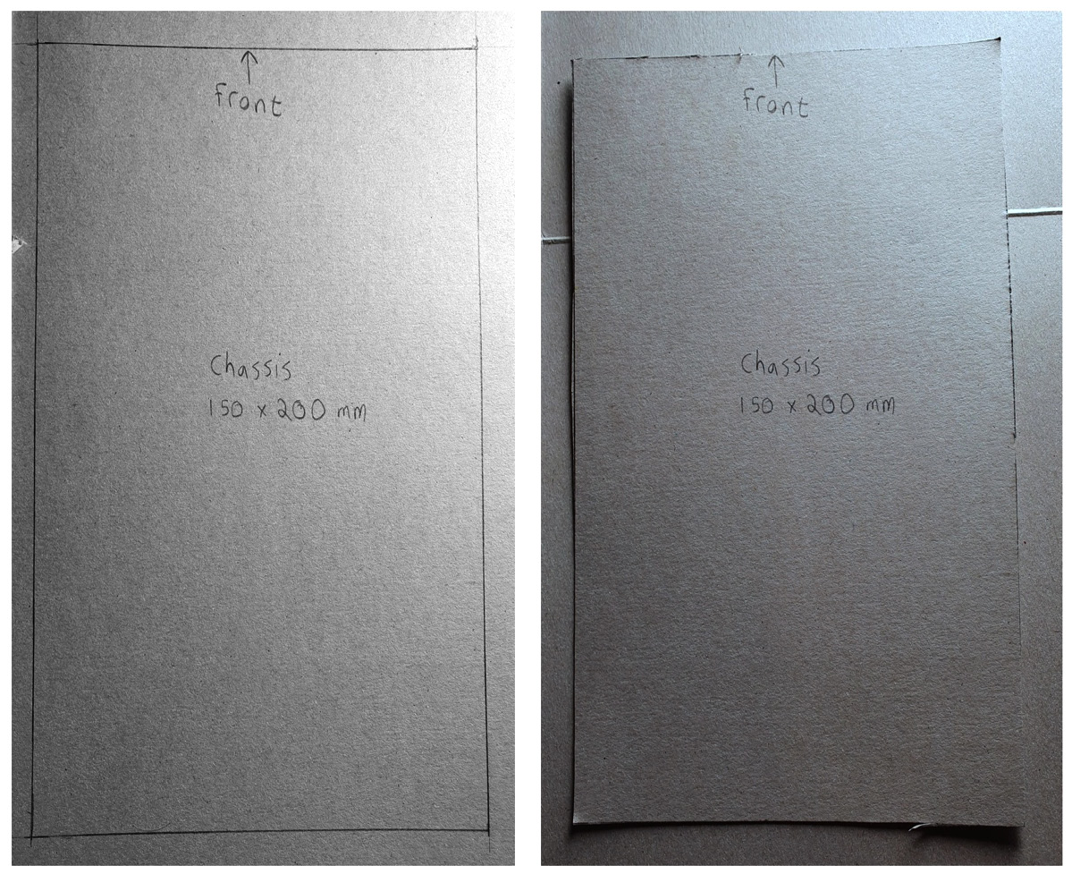
Figure 1.14 – The cardboard chassis
As you can see from the preceding photograph, this is not—at all—intended to be a perfectly neat cut. It is simply meant to be good enough to see where things likely need to go. Give the chassis labels just as we have done so far with the other parts. Additionally, we can label one of the shorter edges of the chassis part as the front.
This is the last item to test fit. Let’s start to arrange these parts.
Arranging the test-fit parts
Now, you should have a set of rectangles representing the different parts. The following photograph shows the parts and how we can arrange them:
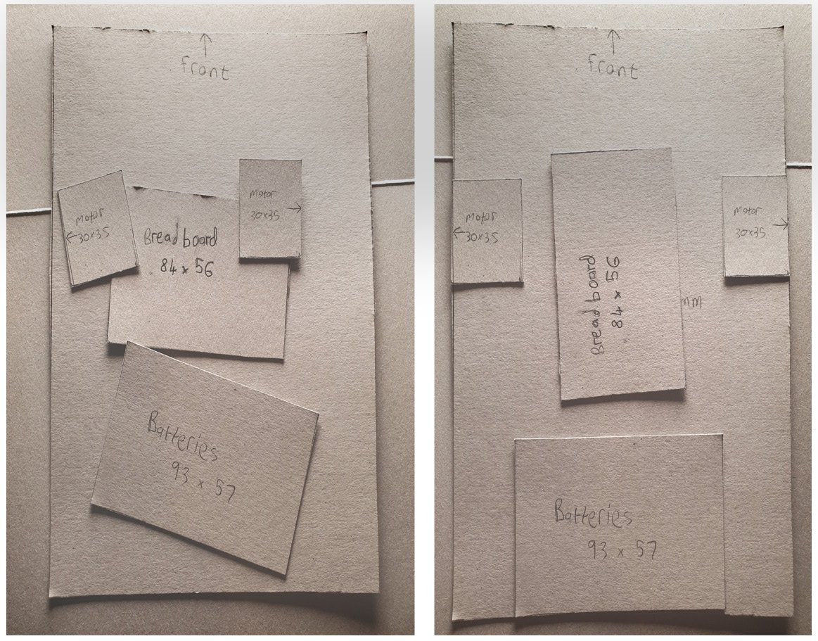
Figure 1.15 – Our test-fit parts in cardboard
The boxes on the left-hand side of Figure 1.15 are correctly proportioned parts and have been placed in a rough position. However, they aren’t properly laid out yet. The right-hand side shows a possible layout.
It’ll be easier to fit motors around the breadboard if we rotate it so that it’s tall instead of wide. We have the batteries at the back of the robot, in the middle, then we have the breadboard in front of them, along the middle. Notice that there is a gap between the batteries and the breadboard—we don’t want any parts to be too close together.
We’ve put the motors on either side of the breadboard, leaving space at the front to expand our robot design.
We have accounted for the major parts of the robot, including computing, power, and motors. There’s also adequate space for expansion. We’ll tune this later as we get deeper into the design, but this shows our combination is viable.
Now that we have our robot design, it’s time to shop for tools and materials!