


Setting up our shader in Unity
With the Blinn-Phong model in mind, we are now ready to implement our shader with Unity’s legacy render pipeline.
The overall process will be to first create our shader and a matching material so that we can assign it to a 3D object in our scene, and then gradually add more and more components to properly re-create the diffuse component of the Blinn-Phong shading model we discussed in the Doing a quick study of the Blinn-Phong shading model section. Before we do anything, however, let’s quickly have a chat about the project requirements for this chapter so that you can test the samples yourself.
Checking your project configuration
Since we are using the built-in graphics here, you will need to create a new test project using the usual Unity 3D template. You can pick the template you want at the creation of your project, in the Unity Hub window, like this:
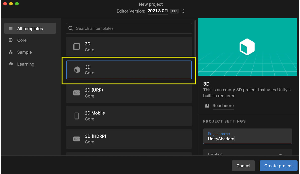
Figure 1.12 – Unity project creation panel in the Unity Hub with the 3D template highlighted
However, if you have already created a project using one of the newest render pipelines (Universal Render Pipeline (URP) or High Definition Render Pipeline (HDRP)), make sure to temporarily turn it off in your project settings if you want to use the shader we will make in this chapter. To do this, follow these steps:
- Go to the Edit | Project Settings... menu.
- Switch over to the Graphics section on the left.
- At the very top of the inspector panel, in the Scriptable Render Pipeline Settings slot, remove the asset reference (set it to None).
This will re-enable the built-in renderer and allow for our legacy shader example to work properly.
Creating the shader file
Time to start writing our Blinn-Phong shader! We will follow these steps to create the shader file:
- First, we will create a new shader asset in our project – to do this, simply right-click in the Project dock in your Unity editor and create a new shader file by navigating through the contextual menu (see Figure 1.13):
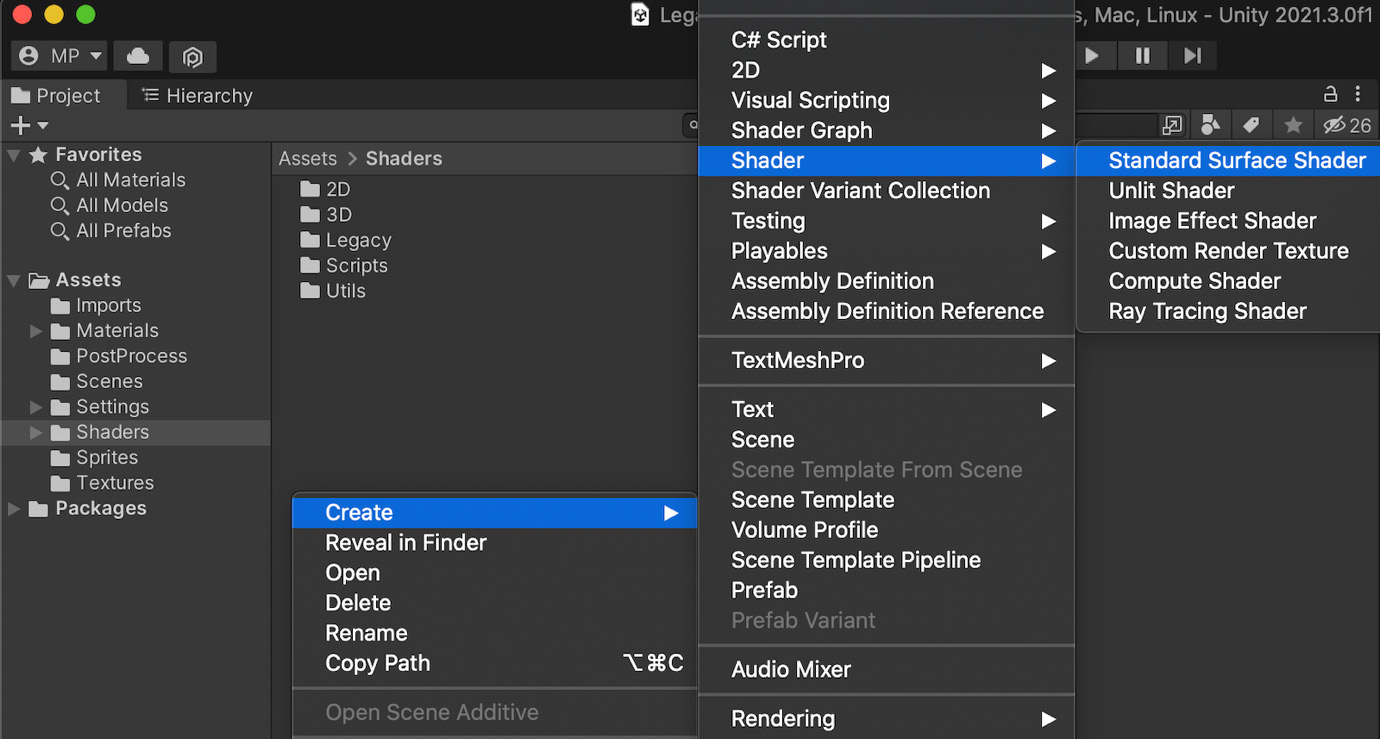
Figure 1.13 – Contextual menu for creating a legacy shader
You can choose whichever preset you prefer – we will remove almost all the auto-generated code to implement the shader from scratch, anyway.
- After you’ve created the asset, double-click on it to open it in an IDE. Unity will have filled the file with a basic shader based on the preset you chose. But to really understand what we are doing, let’s clear this and remove everything except for the top-level enclosing brackets with the name of our shader – your file should now look like this:
Shader "Custom/BlinnPhong"
{}
Defining the name and category of your shader
The first line in our shader file defines the unique reference of our shader as a path. Every forward slash in this quoted string corresponds to a level in the shader menu that unfolds in a drop-down list in the inspector panel when you pick the shader of a material. You can, of course, adjust it to your liking to organize the shaders differently in your project.
- Then, go back to the Unity editor. You will notice that your shader is recompiled automatically. By right-clicking on your shader asset in the Project window, you will be able to create a material that uses this specific shader with the contextual menu:
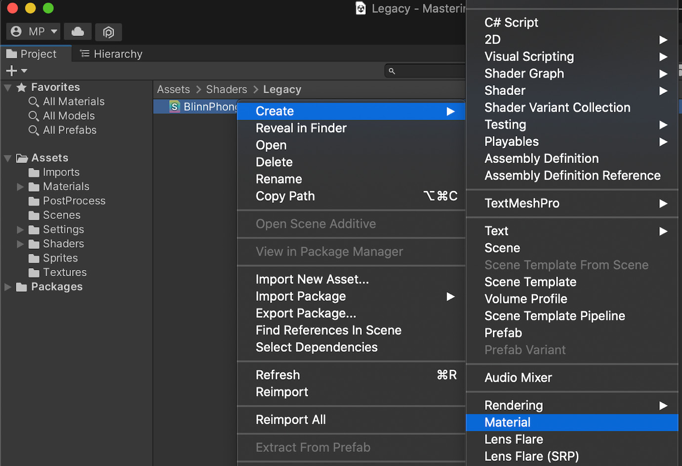
Figure 1.14 – Contextual menu for creating a material from a shader
- To finish setting up the test project, you need to add a 3D object (for example, a primitive sphere or a capsule) to your current Unity scene and assign it the material you created. Since this shader code is invalid, you will notice that the object appears in a magnificent flashy pink, as in Figure 1.15:
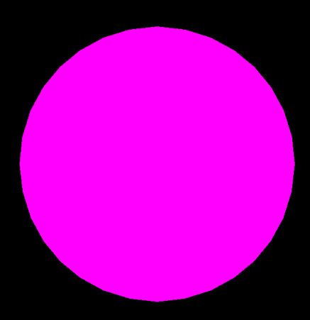
Figure 1.15 – Debug display of an invalid Unity shader
Even if it doesn’t look right, it does verify that our shader asset is indeed used for the object’s in-game render. But now, we should obviously fix our shader and turn it into a real Blinn-Phong!
The very first component we will implement will be the diffuse lighting. As we saw in the Doing a quick study of the Blinn-Phong shading model section, this requires that we define a color for our object and that we get the normal of our vertices to compute the diffuse contribution for the corresponding pixel.
The first step is to prepare the structure of our shader and, in particular, a property for our object color:
- To begin with, let’s declare a new
_Colorproperty for our shader and give it a default value of(1, 1, 1, 1), or in other words, pure white:Shader "Custom/BlinnPhong" { Properties { _Color ("Color", Color) = (1, 1, 1, 1) } } - Next, we will add our
SubShaderandPassblocks with a basic tag to specify that our shader is meant to be rendered as opaque:Shader "Custom/BlinnPhong" { Properties { _Color ("Color", Color) = (1, 1, 1, 1) } SubShader { Tags { "RenderType" = "Opaque" } Pass {} } }
At this point, we have recomposed our famous ShaderLab nested structure, and all that is left to do is fill the Pass block with our low-level shader code. For now, this code will be fairly simple – we will define very basic appdata and v2f structures, have our vertex shader code pass along the data unchanged, and make the fragment shader output our color directly, such as for an unlit shader. We will follow these steps:
- First of all, let’s add the CG start and end instructions, the pragmas to identify our vertex and fragment shader functions in the script, the usual inclusion of the
UnityCG.cginclibrary, and the declaration of the low-level_Colorvariable to match our exposed property:Pass { CGPROGRAM #pragma vertex vert #pragma fragment frag #include "UnityCG.cginc" float4 _Color; ENDCG } - Then, let’s define our simple
appdataandv2fstructures. For the time being, we will simply use the position of the vertices, so each structure will have a singlefloat4field with thePOSITIONorSV_POSITIONsemantic:Pass { CGPROGRAM ... struct appdata { float4 vertex : POSITION; }; struct v2f { float4 vertex : SV_POSITION; }; ENDCG } - Our data is now ready to be used as input or output by our
vertvertex shader function. We just have to convert our incoming vertex 3D position into the equivalent 2D position in clip-space, thanks to Unity’s built-inUnityObjectToClipPosfunction, like this:Pass { CGPROGRAM ... v2f vert (appdata v) { v2f o; o.vertex = UnityObjectToClipPos(v.vertex); return o; } ENDCG } - And finally, we can create a one-line fragment shader function,
frag, that simply returns the color we defined for each pixel of our object:Pass { CGPROGRAM ... float4 frag (v2f i) : SV_Target { return _Color; } ENDCG }
You can now come back to the Unity editor, let the shader recompile, and admire your brand-new white shape in the Game view. At this point, we have made a basic unlit shader with Unity’s built-in rendering pipeline that we can adjust the color of by tweaking the Color property exposed in the material’s inspector, as shown in this screenshot:
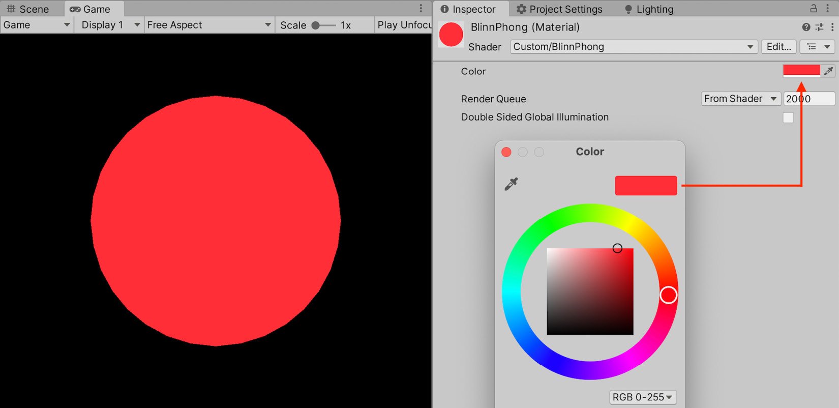
Figure 1.16 – Simple unlit shader with a color property that can be set in the inspector
The next step is to modify our unlit shader to compute some diffuse lighting.
Implementing the diffuse lighting
All right, at this point, we have a basic shader structure that allows us to render our object as unlit. But, of course, this is not what we want! It is time to draw from our previous reminders on diffuse lighting.
In the Doing a quick study of the Blinn-Phong shading model section, we saw that our diffuse component could be computed based on the normal of the N surface and its direction to the light, L. Let’s go through each of those vectors one by one and see how we can calculate them in Unity!
First of all, the normal is easy enough to get. We can simply ask Unity to pass it in our input vertex data structure by adding a float3 field with the NORMAL semantic, like this:
struct appdata {
    float4 vertex : POSITION;
    float3 normal : NORMAL;
};
Then, we have to transfer it over to the output data structure in our vertex shader function. The interpolators don’t support the NORMAL semantic in the same way – instead, we have to store this data in our first UV set denoted by the TEXCOORD0 semantic. Then, in our vert function, we need to use another Unity built-in function to convert the normal from the object space to the world space, UnityObjectToWorldNormal, as follows:
struct v2f {
    float4 vertex : SV_POSITION;
    float3 normal : TEXCOORD0;
};
v2f vert (appdata v) {
    v2f o;
    o.vertex = UnityObjectToClipPos(v.vertex);
    o.normal = UnityObjectToWorldNormal(v.normal);
    return o;
}
And finally, we retrieve it in the fragment shader from our interpolated data, and we apply the normalization step to get our N vector:
float4 frag (v2f i) : SV_Target {
    // get normalized normal for fragment
    float3 N = normalize(i.normal);
    return _Color;
}
A quick note on normalization
Even though the per-vertex normals Unity gives us in the appdata input data structure are normalized, we do need to ensure that the normal we get in our fragment shader is normalized too. This is because, since it’s interpolated, there is no guarantee that this blended normal actually has a length of 1. Although it will not cause any visual issues for the diffuse lighting, you will notice a disturbing faceting with the specular highlights if you forget to re-normalize this vector before the computations.
Next up, we will get our L vector. Remember that this is the direction from the surface to the light source and that, here, we are assuming there is only one main directional light.
Luckily, this is very easy to get in Unity – the engine directly offers us a built-in float4 variable called _WorldSpaceLightPos0 that contains the direction of directional light or the position of a spot or point light. The fourth component is either 0 if the light is directional or 1 if the light is not directional. So, in our case, we just have to extract the first three components of this vector with the usual HLSL swizzling to get our L vector:
float4 frag (v2f i) : SV_Target {
    // get normalized normal for fragment
    float3 N = normalize(i.normal);
    // get (outgoing) light vector
    float3 L = _WorldSpaceLightPos0.xyz;
    return _Color;
}
We now have everything we need to compute our lambertian reflectance, using the formula from the Doing a quick study of the Blinn-Phong shading model section:
float4 frag (v2f i) : SV_Target {
    // get normalized normal for fragment
    float3 N = normalize(i.normal);
    // get (outgoing) light vector
    float3 L = _WorldSpaceLightPos0.xyz;
    // diffuse lighting (Lambert)
    float lambert = saturate(dot(N, L));
    return float4(lambert * _Color.xyz, 1);
}
At this point, if you come back to the Unity editor and wait for the shader to recompile, you’ll have a shader that handles diffuse lighting and takes into account the color of the object, specified by the _Color property as we defined in step 1 of our structure definition in the Creating the shader file section. For example, if you set the color to gold-yellow, you will get something similar to Figure 1.17:
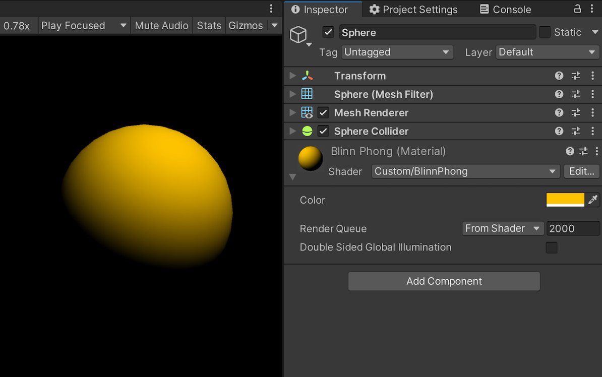
Figure 1.17 – Diffuse shader with a color property for the surface
To wrap up our implementation of the diffuse lighting, we should also make sure to get the color of the light into the mix. For now, you’ll notice that if you try to change the color of the directional light in your scene, nothing happens – the object still appears yellow.
The solution here is to include the UnityLightingCommon.cginc library so that we can access its _LightColor0 variable and multiply it with our lambert variable:
{
    #include "UnityLightingCommon.cginc"
    ...
    float4 frag (v2f i) : SV_Target {
        float3 N = normalize(i.normal);
        float3 L = _WorldSpaceLightPos0.xyz;
        float lambert = saturate(dot(N, L));
        float3 diffuseLight = lambert * _LightColor0.xyz;
        return float4(diffuseLight * _Color, 1);
    }
}
And here we are! If you try to change the color of either the object or the light, you’ll see that now they both impact the final color of the pixels in the render with the same additive mix as we experience in real life. Figure 1.18 shows how the same white sphere (meaning, with a _Color property equal to full white) results in different colors depending on the color of the light:
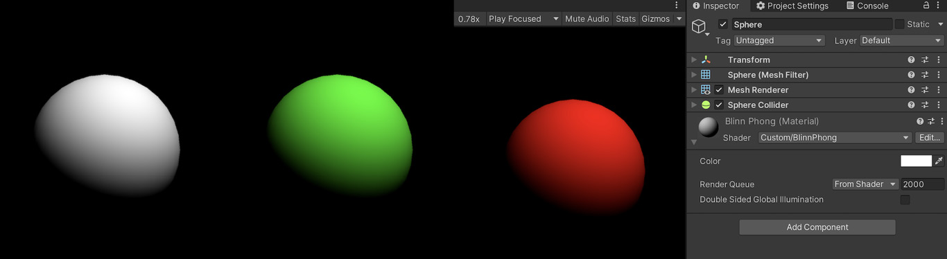
Figure 1.18 – Examples of renders with a constant white surface for the sphere but a changing light color
With that first component implemented in our Blinn-Phong shader, let’s move on to the two others: the ambient and specular lighting!