Reader small image

You're reading from  Learn Robotics Programming - Second Edition

Product typeBook
Published inFeb 2021
PublisherPackt
ISBN-139781839218804
Edition2nd Edition
Concepts
Right arrow
Author (1)
Danny Staple
Danny Staple
author image
Danny Staple

Danny Staple builds robots and gadgets as a hobbyist, makes videos about his work with robots, and attends community events such as PiWars and Arduino Day. He has been a professional Python programmer, later moving into DevOps, since 2009, and a software engineer since 2000. He has worked with embedded systems, including embedded Linux systems, throughout the majority of his career. He has been a mentor at a local CoderDojo, where he taught how to code with Python. He has run Lego Robotics clubs with Mindstorms. He has also developed Bounce!, a visual programming language targeted at teaching code using the NodeMCU IoT platform. The robots he has built with his children include TankBot, SkittleBot (now the Pi Wars robot), ArmBot, and SpiderBot.
Read more about Danny Staple

Right arrow

Chapter 16: Diving Deeper with the IMU

In Chapter 12, IMU Programming with Python, we read data from an inertial measurement unit (IMU). We've now learned a bit more about processing sensor data, using math and pipelines to make decisions.

In this chapter, we will learn how to get calibrated data from the IMU, combine data from the sensors, and use this to make a robot have absolute orientation-based behavior. On the way, we'll see algorithms for better precision/speed or accuracy.

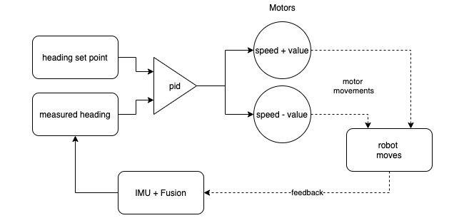
By the end of the chapter, you will be able to detect a robot's absolute orientation, display it on a screen, and incorporate this with the Proportional-Integral-Derivative (PID) behaviors.

In this chapter, we're going to cover the following main topics:

  • Programming a virtual robot
  • Detecting rotation with the gyroscope
  • Detecting pitch and roll with the accelerometer
  • Detecting a heading with the magnetometer
  • Getting a rough heading from the magnetometer...

Technical requirements

For this chapter, you will need the following items:

For the complete code for this chapter, go to https://github.com/PacktPublishing/Learn-Robotics-Programming-Second-Edition/tree/master/chapter16.

Check out the following video to see the Code in Action: https://bit.ly/2LztwOO

Programming a virtual robot

We will first detect our robot's orientation; it would be useful to show this as a 3D robot model. This part builds upon the Representing coordinate and rotation systems section in Chapter 12, IMU Programming with Python. In this section, we will construct a simple model of our robot in VPython.

Modeling the robot in VPython

We'll use shapes, known as primitives, to model the robot. They have a position, rotation, size, and color. The height-and-width parameters match the VPython-world coordinate system (see Figure 12.14 – The robot body coordinate system in Chapter 12, IMU Programming with Python), so we must rotate things to match the robot body coordinate system.

First, we need to collect some robot measurements. The following diagram shows where they are. Once the major measurements are made, estimates can be used for smaller measurements:

Figure 16.1 – Measurements for the virtual robot

...

Detecting rotation with the gyroscope

We've had some raw data from the gyroscope, but to use it more effectively, we'll need to perform two operations, calibrating the gyroscope, and then integrating it, as shown in the following diagram:

Figure 16.4 – The gyroscope data flow

Figure 16.4 shows the data flow, and we will look closer at the concepts later in this section. The first operation is shown at the top, which shows the gyroscope data going through an offset calibration to take out errors. This gives us a calibrated gyroscope, with a rate of change in degrees per second (per axis)—shown by the arrow around the circle. The gyroscope makes a relative measurement.

The lower part of the diagram is the second operation, combining delta time with the calibrated gyroscope (gyro). We need to integrate that to find an absolute measurement. An integrator multiplies an input value by delta time and adds this to a previous result....

Detecting pitch and roll with the accelerometer

In Chapter 12, IMU Programming with Python, we were getting a vector from the accelerometer, but we need to calculate angles to consider using it alongside the gyroscope and magnetometer. To use this to rotate things, we need to turn this vector into pitch-and-roll angles.

Getting pitch and roll from the accelerometer vector

The accelerometer describes what is going on in Cartesian coordinates. We need to convert these into a pair of pitch-and-roll angles perpendicular to each other. In Chapter 12, IMU Programming with Python, the Coordinate and rotation systems section shows roll as taking place around the x axis, and pitch as taking place around the y axis.

A crude but effective way to consider this is as two planes. When rotating around the x axis, you can take a vector in the yz plane and find its angle. When turning around the y axis, then you consider the xz plane instead. Take a look at the next diagram:

...

Detecting a heading with the magnetometer

We saw in Chapter 12, IMU Programming with Python, how to plot a vector from the magnetometer, and how magnetic metal (such as bits of steel and iron) will interfere with it. Even the pin headers on the IMU board interfere. We can calibrate to compensate for this.

Getting X, Y, and Z components aren't that useful; we want a heading relative to a magnetic North. We can see how to use this for precise turns.

This section needs a space, with very few magnets present. Laptops, phones, speakers, and disk drives interfere with this sensor. Use a map compass to reveal magnetic fields in your space. I recommend making the standoff stalk on the robot as long as the cable allows, putting more standoffs in; the robot's motors have a strong magnetic field of their own.

Please avoid starting with the robot facing South—this will cause some odd results, which we will investigate and fix later. Starting with the robot roughly North...

Getting a rough heading from the magnetometer

Now that we've got calibration settings, we can start using magnetometer readings to estimate where North is, like a compass. The words heading and yaw mean the same thing —which way we face relative to a reference point—in this case, magnetic North. Let's see how we can do this. Have a look at the following screenshot:

Figure 16.15 – Getting an approximate heading from the magnetometer

Figure 16.15 shows a method we will build. It takes the magnetometer with calibration data applied and uses atan2, as we did with the gyroscope to approximate the heading. We can also add a rough compass with it too.

Let's make this, as follows:

  1. Create a plot_mag_heading.py file. Start with the imports, as follows:
    import vpython as vp
    from robot_imu import RobotImu
    from delta_timer import DeltaTimer
    import imu_settings
  2. We can initialize the RobotImu with the settings, like this...

Combining sensors for orientation

We've seen how we combined the accelerometer and gyroscope to get smooth readings for pitch and roll. We can combine the sensors again to correctly orient and smooth the magnetometer readings too. This system allows us to approximate the absolute orientation of the robot.

Take a look at the following data flow to see what we are doing—it builds on the previous stages:

Figure 16.17 – Fusing all three sensors

Figure 16.17 starts on the left with data from our previous stages. We have the filtered pitch and roll in gray because it's also an output. There's the calibrated gyroscope yaw, delta time, and also the calibrated magnetometer as inputs. The filtered pitch and roll go through the tilt-compensate box, where we rotate the magnetometer vector. The magnetometer data then goes through an xy-to-polar box, using the atan2 function to get a heading.

Above this, the calibrated gyroscope yaw...

Driving a robot from IMU data

In previous chapters, we saw how to use the PID algorithm, and in this chapter, how to detect a pitch, roll, and yaw from a magnetometer. Our robot can't move its pitch or roll, but it can change its heading.

In this demonstration, we'll get the robot to stay on course—to try to track North regardless of where we turn it. Let's see how. Have a look at the following diagram:

Figure 16.19 – Drive to heading behavior

Figure 16.19 shows the flow of data. The left of the diagram starts with a measured heading, and a heading setpoint going into a PID—the error value will be the difference between the two. The measured heading has come from the IMU + Fusion algorithm. We use the PID output to drive the motors so that they move at a fixed speed plus or minus the value, so the robot will turn to reduce the error. The robot moving will feed back into the IMU + Fusion algorithm, looping through...

Summary

In this chapter, you've seen how to combine the IMU sensors to approximate an absolute orientation in space. You've seen how to render these in graphs and how to display them onscreen with a virtual robot. You've then seen how to hook this sensor system up to a PID controller and motor to get the robot to drive.

You've learned a little of the math needed to convert between vector components and angles, in 3D, along with how to use complementary filters to compensate for noise in one system and drift in another. You've started to see multiple sensors fused together to make inferences about the world. Your block diagram and data flow skills have been exercised, and you have had more practice with the PID algorithm.

In the next chapter, we will look at how you can control your robot and choose behaviors from a menu with a smartphone.

Exercises

Here are some ideas to further your understanding, and give you some ideas for more interesting things to do with the concepts from this chapter:

  • A reader can use more colors and complicated shapes to make a better robot model. It's not the purpose of this chapter, but it is a fun and rewarding way to get more familiar with VPython.
  • Our magnetometer settings were hardcoded, going into a Python file. It is good practice to load settings from a data file. A good starting point can be found at http://zetcode.com/python/yaml/.
  • Could the visual robot be used to display or debug the other sensors and integrations?
  • Could you combine the absolute positioning here with the encoders to make a square with very accurate turns?

Further reading

For more information on the topics covered in this chapter, refer to the following:

lock icon
The rest of the chapter is locked
You have been reading a chapter from
Learn Robotics Programming - Second Edition
Published in: Feb 2021Publisher: PacktISBN-13: 9781839218804
Register for a free Packt account to unlock a world of extra content!
A free Packt account unlocks extra newsletters, articles, discounted offers, and much more. Start advancing your knowledge today.
undefined
Unlock this book and the full library FREE for 7 days
Get unlimited access to 7000+ expert-authored eBooks and videos courses covering every tech area you can think of
Renews at $15.99/month. Cancel anytime

Author (1)

author image
Danny Staple

Danny Staple builds robots and gadgets as a hobbyist, makes videos about his work with robots, and attends community events such as PiWars and Arduino Day. He has been a professional Python programmer, later moving into DevOps, since 2009, and a software engineer since 2000. He has worked with embedded systems, including embedded Linux systems, throughout the majority of his career. He has been a mentor at a local CoderDojo, where he taught how to code with Python. He has run Lego Robotics clubs with Mindstorms. He has also developed Bounce!, a visual programming language targeted at teaching code using the NodeMCU IoT platform. The robots he has built with his children include TankBot, SkittleBot (now the Pi Wars robot), ArmBot, and SpiderBot.
Read more about Danny Staple