


Doing a quick study of the Blinn-Phong shading model
Working with shaders can be tricky when you don’t know exactly what you are planning. Although skilled technical artists can get away with some shots in the dark and develop the logic of their shader as they implement it, it is often more reassuring to anticipate the computation and the composition of the different components your shader will use.
This process of listing the features your shader needs to have is what we call defining its shading model. It is crucial for beginners and often pretty useful for more advanced developers, too.
To understand what this step implies, we will define the Blinn-Phong shading model we want to implement here with an easy and well-known lighting model: the ambient/diffuse/specular model. We will first discuss the basic diffuse lighting, then see how to add ambient lighting, and finally dive into the specular lighting to understand how to implement all three of them in our shader.
Using diffuse lighting for a basic render
Diffuse lighting is often the first step to implementing any kind of lighting for your shader. It is the direct illumination of the object by the light, or in other words, the effect by which the surface re-emits some or all of the incoming light that hits it. The color of the object depends on which part of the light is absorbed and which part is re-emitted.
This lighting does not depend on the direction you are currently facing. It is how you can render a 3D matte surface, and it is usually what you think of when you’re asked to picture a 3D object floating about like this:
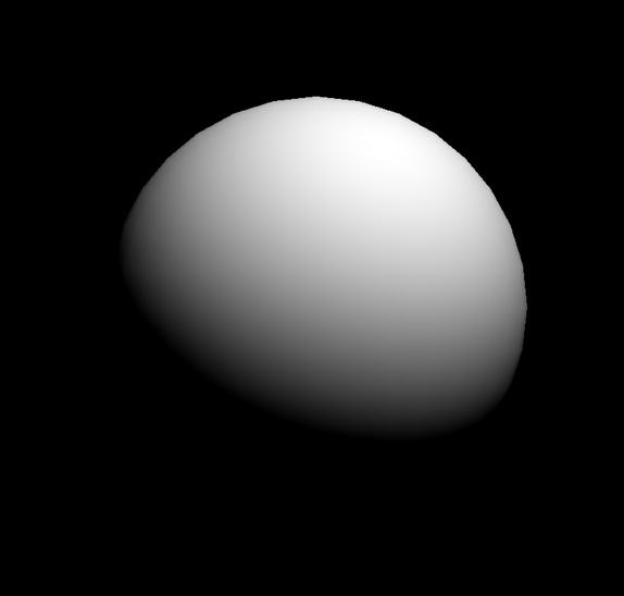
Figure 1.1 – A basic diffuse lighting of a 3D sphere
In the case of the Blinn-Phong model, we can compute this base surface brightness based on the position of our light source and the normal of said surface. Let’s consider a schematic visualization of this direct illumination of the surface:
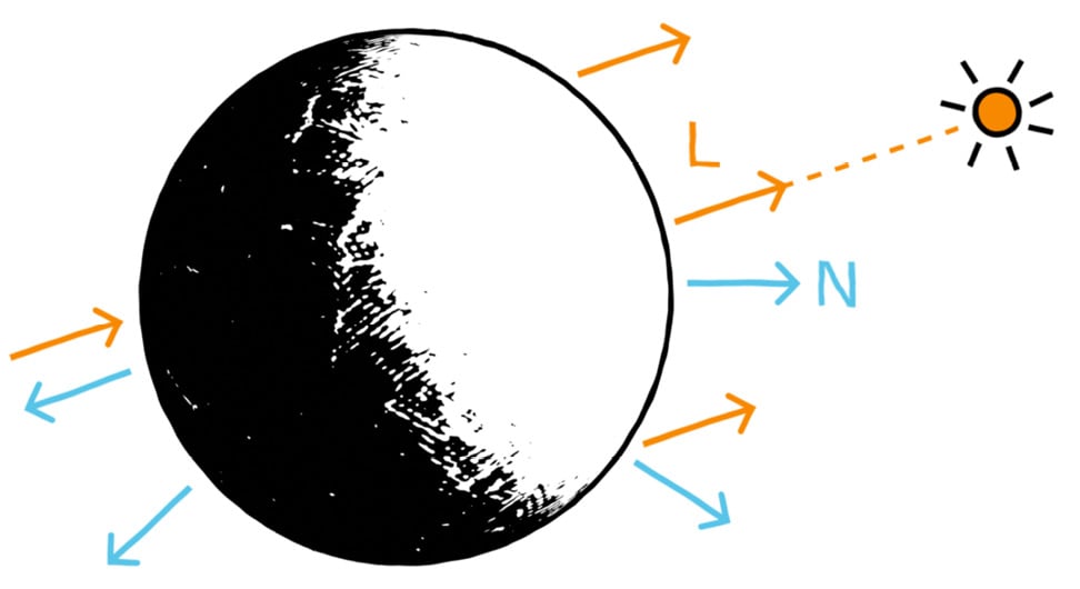
Figure 1.2 – Light vector (L) and normal vector (N), used to compute the diffuse lighting component
This diagram introduces two relevant vectors for the computation of the diffuse lighting:
- Light vector (
L): This is the direction from the surface to the light source. Since we are assuming a single directional light source that is infinitely far away, this vector will be the same for each pixel of the object. - Normal vector (
N): This is the outgoing direction from the surface that is orthogonal to its tangent plane.
Direction versus vector?
Throughout this section, we will define and use various vectors that are in all directions. This basically means that we are only interested in the line along which the vector spreads and which side the arrow points; the length of the vector, however, is ignored and considered normalized to 1.
We can see in Figure 1.2 that we want the diffuse component to be maximal when the surface is facing the light and minimal when it faces away from it. This can easily be computed by taking the dot product of the L and N vectors clamped to the [0, 1] range. This clamping can be done directly using the saturate function, which is common in shader languages.
Since this reflectance process is called the lambertian reflectance, this black-to-white mask is often called a lambertian (lambert), and we can express it as:
float lambert = saturate(dot(L, N));
Then, to take into account the color of the light source, lightColor, we need to multiply this value by the color variable (expressed as or cast to float3):
float3 diffuseLight = saturate(dot(L, N)) * lightColor.xyz;
Finally, to also consider the color of the object, color, we simply need to re-multiply our colored diffuse lighting by this other color (again, expressed as or cast to float3):
float3 diffuseColor = diffuseLight * color;
As we will see in the Setting up our shader in Unity section, if we implement this into our fragment shader function, then we will get something similar to Figure 1.1.
Now that we have seen how easy it is to compute the diffuse lighting, let’s see go ahead and see why ambient lighting can be a quick way to improve our lit shaders.
Better integrating the object – thanks to ambient lighting
The diffuse lighting, we just discussed is usually the first step to having your object exist in a render: it is a way to pull it out of the shadows by defining how light sources illuminate its surface. However, this first component can only go so far – in particular, the diffuse lighting is not aware of the surroundings of the object and the environment it is in.
This is why, usually, to help integrate your object into your scene, you also need to consider your environment’s ambient lighting.
Ambient light is a light that does not come from any specific source – it is everywhere in the scene and illuminates slightly all the objects from all around. In a nutshell, it is light with neither an origin nor a direction. It is the light that bounces around the environment, and that allows us to see our shapes in a 3D render even if there are no specific light sources, as shown in Figure 1.3:
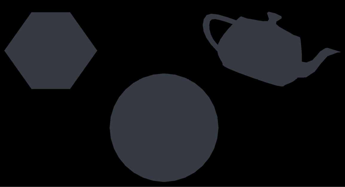
Figure 1.3 – Ambient lighting of a few random 3D shapes
It is also why, in real life, most of the time, even the side of an object that is in the shadows is not completely dark. Figure 1.4 shows the difference between a simple diffuse material without any ambient lighting and another that integrates this second component and therefore does not have a fully black side opposite the main light:
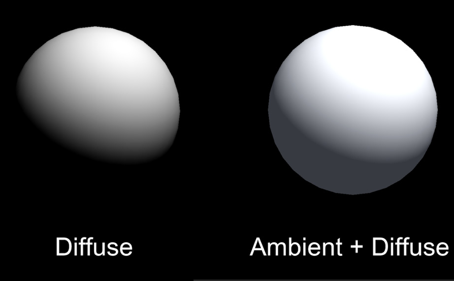
Figure 1.4 – Comparison between a shader with only a diffuse component and a shader with both the diffuse and ambient components
Ambient light is useful in many cases, most notably whenever you want to control the overall brightness of the scene without having to adjust each light individually. For example, if you want to bring out the colors of a cartoon style, ambient light can be a nice solution.
In all generality, the ambient light component is computed as a product of intensity and color:
float3 ambientLight = ambientIntensity * ambientColor;
Note that, this time, we shouldn’t multiply ambientLight by the color of the object because this ambient component is global to the scene and applies the same to all the shapes in the render. So, since we want this ambient lighting to be the minimum of the light that all objects in the scene get, we just need to add to our previous diffuse component to get the combination of both:
float3 diffuseAndAmbientColor = diffuseColor + ambientLight;
Of course, the tricky part can be to actually get the value of the ambientIntensity and ambientColor variables: depending on the software you use, this information can be more or less hidden inside the engine. However, we will see in the Adding the ambient and specular components section that in Unity, this data can be retrieved pretty easily inside of a shader code.
We are now up to speed with two light components out of three... finally, last but not least, let’s recall the fundamentals of specular lighting!
Adding some light reflections with a specular
Until this point, the diffuse and ambient components we discussed were fairly easy to describe, and, in particular, they did not depend on the position of the camera at all. No matter where you render your diffuse or ambient from, the result will always be the same.
Specular lighting, on the other hand, is different. It is what causes a shiny surface (typically a plastic or a metal) to have some bright spots, glossy edges, and lighter faces, like this:
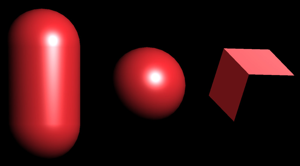
Figure 1.5 – Basic specular lighting of a capsule, a sphere, and a cube with a single directional light
Specular reflection is like a mirror reflection – if the surface is smooth enough, the incoming light rays are reflected toward the viewer’s eye and create those localized highlights. The specular component, therefore, depends on three vectors:
- The (normalized) normal vector of the surface,
N, as discussed for diffuse lighting - The direction from the surface to the light source,
L, as discussed for diffuse lighting - The direction from the surface to the camera is often called the view vector and is denoted as
V
And this is where we are finally going to talk about the “Blinn-Phong” we named our shader after! The Blinn-Phong reflection model is an improvement on the initial Phong model, both of which are methods for computing the speculars on a surface based on those three vectors.
The Phong model is more intuitive to understand; however, in practice, it is often less efficient and less realistic than the Blinn-Phong. This is why we are implementing the latter here. Still, to become familiar with how to compute the bright spots of a smooth surface in our render, let’s first quickly go through the Phong technique.
In short, the Phong reflection model tries to determine how close the V vector is and the exactly reflected light vector, R. Figure 1.6 shows this auxiliary variable, which is simply the outgoing ray of light after L has bounced off the surface:
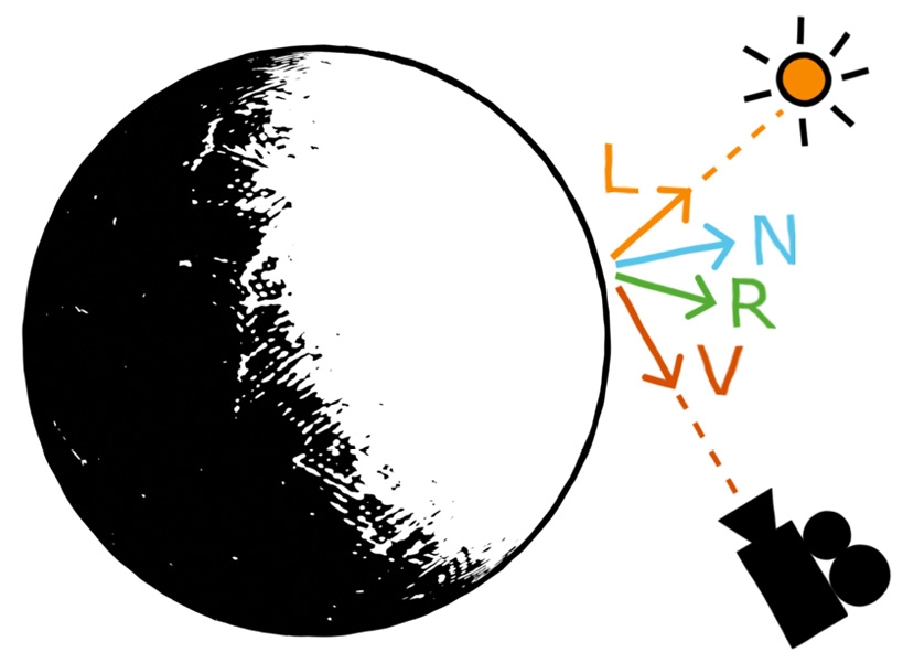
Figure 1.6 – Light vector (L), normal vector (N), view vector (V), and reflected light vector (R), used to compute the Phong specular lighting component
Once again, the High-Level Shader Language (HLSL) shaders have plenty of useful built-in functions for this type of operation. Here, for example, we can use the reflect function and give it in the incoming vector (meaning, our outgoing light vector, L, but reversed) and the normal vector, N, to reflect around:
float3 R = reflect(-L, N);
OK, so – the Phong model checks how close we are to looking directly at the light source in a mirror, with the mirror being our object’s surface. As in our diffuse computation, the “closeness” of two vectors is computed using a dot product. This leads to the following formula for Phong specular highlights:
float3 specularLight = saturate(dot(V, R));
If we implement this model and show only our specular component, we then get something resembling Figure 1.7:
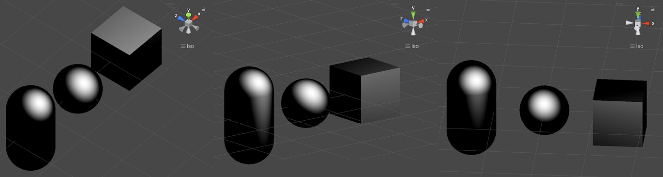
Figure 1.7 – Phong specular highlights on a capsule, a sphere, and a cube with a single directional light
As you can see in this screenshot, the specular does indeed depend on the position of the camera (you can look at the gizmo in the top-right corner to see the current view direction); however, it is not exactly the bright spot we were expecting.
This is because another important concept for specular lighting is the glossiness of the surface – although it is sometimes configured via its related opposite quantity, the roughness. The glossiness basically determines how smooth the surface is – if it is completely smooth, as a perfect mirror, then only a view vector perfectly aligned with the reflected light vector will show the specular. Conversely, if the surface has microfacets and tiny bumps, we will see specular highlights even if we are not looking at the surface in the exact direction of the reflected light vector.
Did you know?
The opposite of a perfect mirror surface, or in other words, a surface that makes specular highlights spread across the entire surface, is called a lambertian surface.
To apply a glossiness parameter to our specular computation, we need to use exponents. More precisely, we need to raise our specularLight variable to the power of our glossiness value, which here we can compute based on the normalized float value, _Gloss, as follows:
specularLight = pow(specularLight, _Gloss);
Because it is used as such, the gloss may also be called the specular exponent – but we will stick with the term “glossiness” here since this is way more common in game engines and 3D software.
Now, by tweaking this value, we can easily change the size of the specular highlighting to get a smooth or rough surface. Figure 1.8 shows various examples of increasing glossiness:
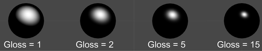
Figure 1.8 – Examples of Phong specular highlights for different values of glossiness
At this point, you might be thinking that we are done and that this Phong model is all we need to create specular lighting. Why would we need to step up to another Blinn-Phong model if this one already gives us these shiny spots and edges?
To really see the issue and why Phong is not as realistic a model as Blinn-Phong, you need to increase the glossiness of your shader to get small-sized specular highlights and have a look at one of the flat faces of the cube when the light is at a steep angle, such as in Figure 1.9:
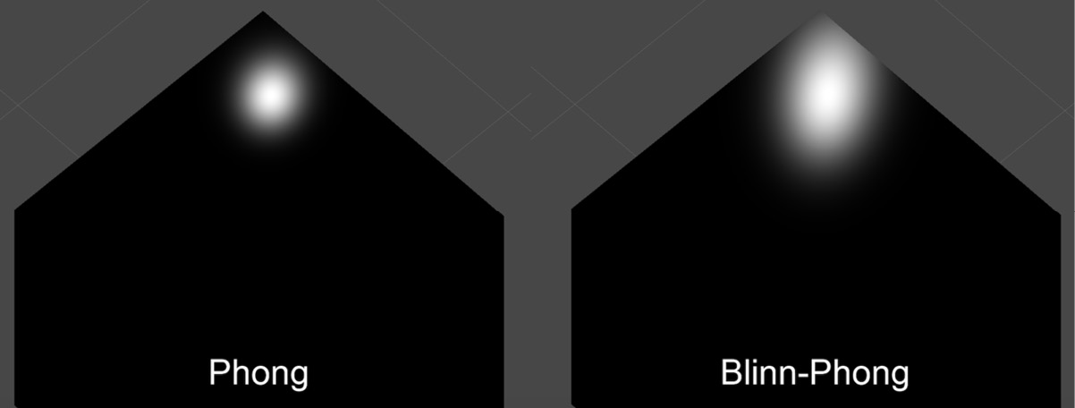
Figure 1.9 – Comparison of the specular highlight on a flat face with a light at a steep angle using a Phong or a Blinn-Phong model
Do you notice how Phong creates a fairly round spot while Blinn-Phong stretches the light on the surface along the direction of the light source, similar to what we have in real life? Phong gives us OK results for round surfaces, but as soon as you have a flat face, it will render way too close to a perfect mirror for most use cases. On the other hand, Blinn-Phong will create anisotropic speculars that are more realistic, which is why we usually switch over to this model in 3D rendering.
In reality, it is very easy to turn Phong into Blinn-Phong. The idea is that instead of computing the following:
float3 specularLight = saturate(dot(V, R));
We will instead calculate this:
float3 specularLight = saturate(dot(N, H));
Where H is the normalized average vector between V and the L light vector called the halfway vector (see Figure 1.10):
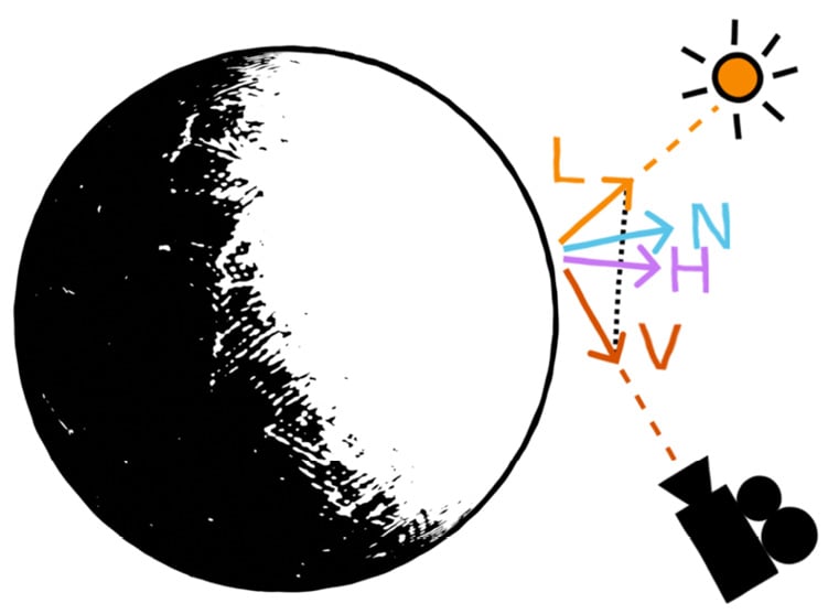
Figure 1.10 – Diagram of the vectors required to compute the Blinn-Phong specular lighting component
The result will be approximately the same, but it gives more realistic results, handles steep angles better, and avoids cutting off the light beyond certain angle limits, contrary to Phong.
To get our halfway vector, we can simply sum L and V and normalize the result. To sum up, the Blinn-Phong specular highlights can be computed with the following formulas:
float3 H = normalize(L + V);
float3 specularLight = saturate(dot(N, H));
specularLight = pow(specularLight, _Gloss);
With this implementation, there is, however, an edge case that can cause Blinn-Phong to get slightly off track – if your camera sees the surface at an extreme angle, up to the point that the light gets behind it, then there can be some small unrealistic remnant of light on the surface. This is because we don’t cull the light depending on whether it is behind the surface or not.
To fix this, we can simply use our lambertian from the diffuse lighting. Since, by definition, it is null when the surface does not face the light, we can simply multiply our specularLight variable by a check of the value of lambert, and only take into account the specular if the lambertian is not null:
float3 specularLight = saturate(dot(N, H)) * (lambert > 0);
Just like before for the diffuse component in the Using diffuse lighting for a basic render section, we can, of course, have these specular highlights be colored by the light source color by multiplying them together:
specularLight = specularLight * lightColor.xyz;
But the final question that needs answering is – how is this specular component composited with our two other components, the diffuse and the ambient lighting?
In short, we need to add this new component to the ones we computed before to mix together the previous shading result with these additional shiny spots:
float3 finalColor = diffuseAndAmbientColor + specularLight;
However, there is a little alternative that is interesting to point out. Let’s leave the ambient light aside for now since it depends on the environment and is a global setting. Then, in the previous formula, you’ll notice that the color of the light is taken into account, both in the diffuse and the specular components, but the color of the surface is only injected in the diffuse part. The specular highlights are currently not tinted by the color of the surface itself.
As a general rule, you want to leave the specular highlights as-is, as simple reflections of the light rays. But it can sometimes be interesting to also take the color of the surface into account if you want to (roughly) simulate metalness. Of course, this is a simplified model of a complex phenomenon, and if you need really realistic metal materials, you will probably have to leave Blinn-Phong behind and get into modern physically-based rendering. Still, as an approximation, this little trick of multiplying the specular highlights by the object’s color can create a metal-like feeling, compared to the unaltered speculars that remind us more of plastic, as shown in Figure 1.11:
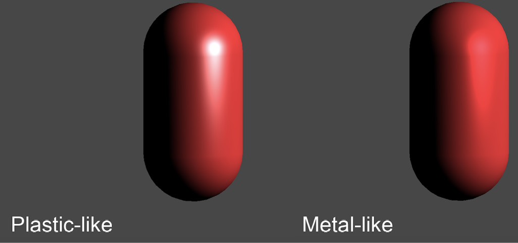
Figure 1.11 – Comparison of a specular model where highlights are not tinted by the surface color (plastic-like) and one where they are (metal-like)
This concludes our theoretical study of the Blinn-Phong shading model. We now have reviewed everything that is relevant to implementing this shader in Unity, so let’s see how to apply all of these formulas in practice!