


Introducing Blender
Blender is a 3D creation suite that can create almost any virtual scene or object.
We'll start exploring Blender by learning about the user interface that you see before you. Knowing what is where is the most essential starting point.
The user interface
As we open up Blender for the first time, we are greeted with a splash screen. This is a helpful menu to get you started when you have a particular project in mind. But for now, just close this menu. Once you've closed the splash screen, your view should look similar to what's shown in the following screenshot:
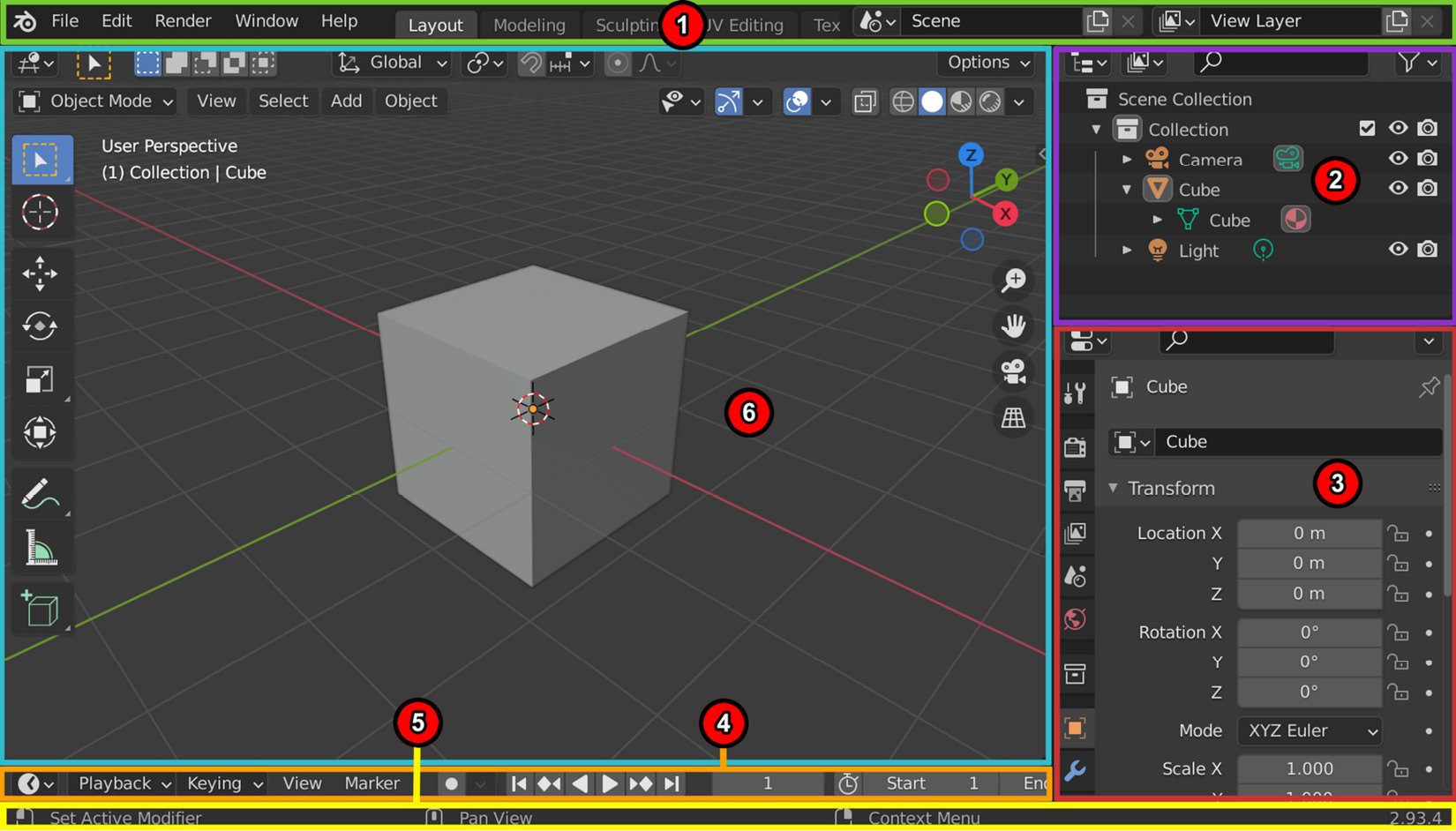
Figure 1.2 – Blender's user interface regions
The numbered areas in the preceding screenshot mark the different user interface regions that I will explain:
- Topbar: This contains menus such as File, Edit, Render, and Help. On the right of that, we have tabs for selecting workspaces. These are like modes for the software, complete with menus and shortcuts. For example, if we want to move objects around the scene, we can use the Layout Workspace tab. Later, when we want to learn about the modeling process, we can switch over to the Modeling Workspace tab.
And, as you have probably already guessed, for 3D sculpting, we can use the Sculpture Workspace tab. The last few tabs we will cover in this book are the UV Editing Workspace and Texture Paint Workspace tabs. Some of the other tabs that you will need for your future projects are the Shading Workspace and Animation Workspace tabs.
- Outliner: This is a list representation of the various objects (meshes, curves, and so on) and elements (cameras, lights, and so on) in the scene. The Outliner can be used for selecting, deselecting, hiding, and organizing these objects and elements in the scene.
- Properties: Here, we will find adjustable properties with tabs for adjusting active data, including the scene and its objects.
- Timeline: This is used for scrubbing and manipulating animation keyframes.
- Status Bar: This is where Blender displays contextual information about mouse and keyboard shortcuts and other statistical information.
- 3D Viewport: This is where you can view what is happening in your virtual 3D world.
In this section, you learned about the basic layout of Blender's user interface and its regions. In the next section, we will take an in-depth look at the various elements of the 3D Viewport.
Elements in the 3D Viewport
The 3D Viewport is where you can view what is happening in your virtual 3D world. The grid pattern shows you the floor plane. The floor grid plane is positioned at 0 on all three axes:
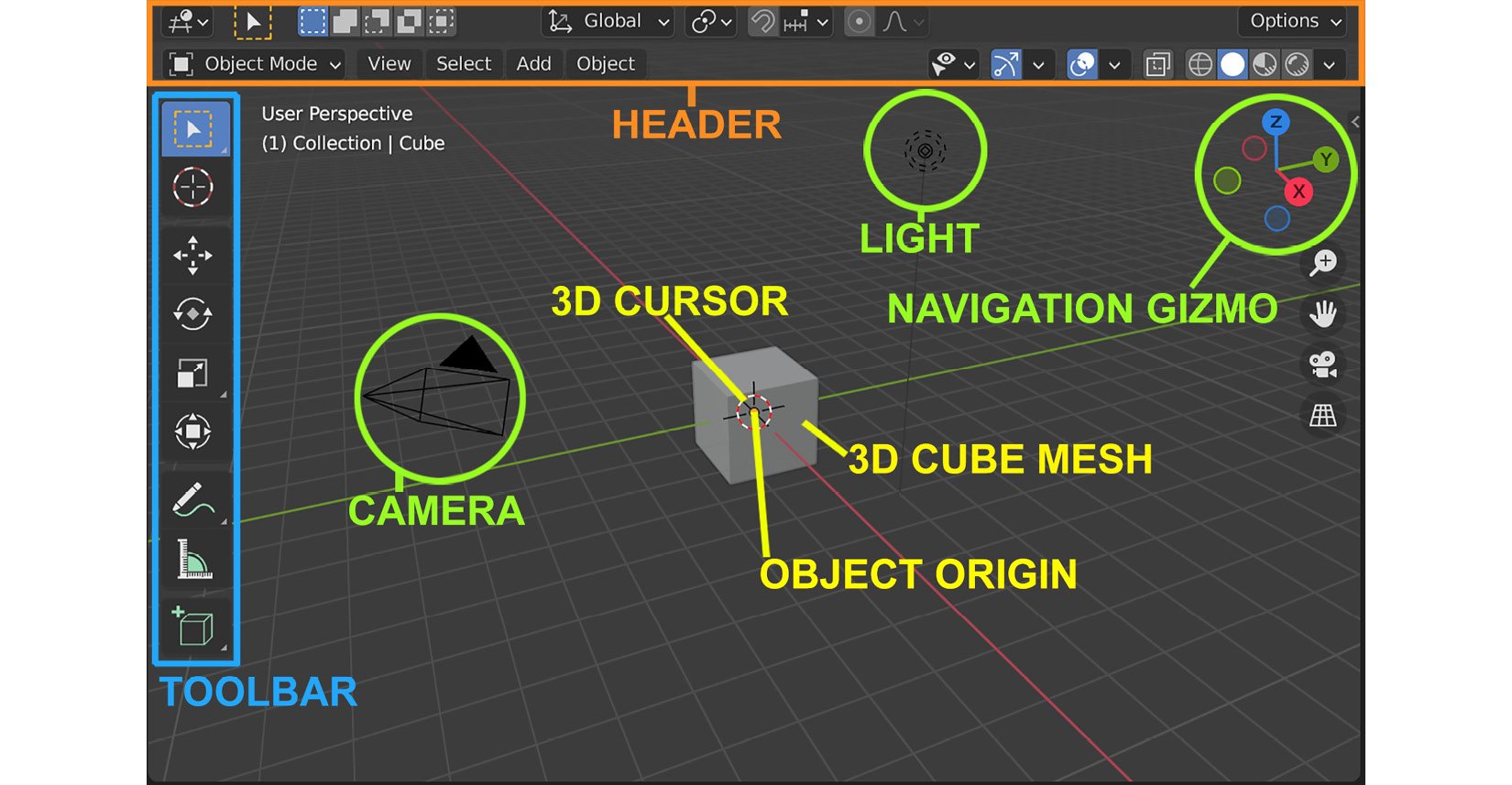
Figure 1.3 – The 3D Viewport's UI elements, shown with the Layout Workspace active
There are a few important items and regions in the 3D Viewport, as highlighted in the preceding screenshot:
- The Header bar: This menu bar acts as a container for menus and commonly used tools. Menus and buttons will change with the editor type and the selected object and mode.
- Toolbar: This menu bar contains a set of interactive tools that change depending on the workspace that's been selected. To show or hide the toolbar, press T.
- Properties region, also known as the N-panel: The Properties region can't be seen in the preceding screenshot because it is hidden by default. To open the Properties region, press N. This will open the Properties region on the right-hand side of the 3D Viewport. The Properties region holds settings for the 3D view and active object. It also provides numeric inputs for editing the Transform tab of your selected item (Location, Rotation, Scale, and Dimensions), as shown in the following screenshot. You can also use the Properties region to edit your 3D view's focal length and viewport clipping:
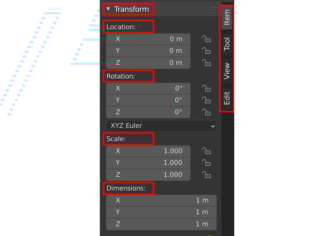
Figure 1.4 – The Properties region
By default, the 3D Viewport will show you some additional items that are automatically loaded on startup. These are the 3D cube mesh, the camera, and the light:
- The 3D cube mesh is a model that provides a good starting point for many modeling tasks.
- The camera is a virtual camera that's used for renders inside Blender, while the light is a virtual light that's used to light our scenes. Neither of these will be used for our tutorial, so we can delete them.
- We also have the object origin. If we focus our attention on the 3D cube mesh in the center of our view, we can see that there is a tiny orange dot right in the center. This indicates the object origin point of our mesh. We will discuss why it is of importance later.
- The 3D cursor is a red-and-white striped circle with crosshairs. This is a very useful tool that will be discussed later.
- Finally, we have the Navigation Gizmo, which can be found in the top-right corner of the 3D Viewport. You can use this gizmo to rotate your view of the 3D scene. We can either click and drag on the navigation gizmo to smoothly change our view, or we can click on one of the dots, which will immediately snap our view to one of the Orthographic views.
Note
Orthographic views are two-dimensional views of a 3D object or scene. These are usually front, back, right, left, top, and bottom Orthographic views.
In this section, you learned about the different elements of the 3D Viewport in Blender. So, now that you have an understanding of the basic user interface, let's continue our journey and learn more about the basics of Blender.
In the next section, we will explore how we can interact with items in the 3D Viewport.
Interacting with the 3D world in Blender
In Blender, there are three basic ways to navigate inside the 3D Viewport – that is, to change your viewpoint of the 3D scene.
Navigating around the 3D view
The following three methods change your viewpoint and can be used to navigate inside the 3D Viewport:
- Zoom: Use the mouse scroll wheel to zoom in or out from the object. Alternatively, you can use Ctrl + click and drag using the middle mouse button to zoom in or out.
- Rotate: Click and drag while pressing the middle mouse button. Hold Alt + click and drag using the middle mouse button to snap the view to the Orthographic view.
- Pan: Press Shift + click and drag using the middle mouse button to pan. Panning means moving the viewpoint from side to side.
Now that you understand how to change your viewpoint in the 3D scene, let's explore how we can interact with items in the 3D Viewport.
Selecting and deselecting items
Once you close the splash screen in Blender, the first thing you will see is a view with a 3D cube in the center.
By default, the 3D cube is already selected. We know this because the 3D cube is highlighted with an orange outline. If an item or component is deselected, it will have no orange outline.
Note
When an item is selected in the 3D Viewport, that same item will also be selected and highlighted in the Outliner. You could use the Outliner to select or deselect items. Any selected/deselected items will also be automatically selected/deselected in the 3D Viewport.
There are a few more ways to select or deselect items, objects, or mesh components in Blender:
- Selecting items directly: Left-click on an item or component directly to select it. To deselect an item or component, you should left-click anywhere in the 3D Viewport.
- Selecting using the selection tools: The select box (located at the top of the toolbar on the left, as shown in Figure 1.3) is the default tool that's used for selection. To use this tool, press the left mouse button and drag over the items or components you want to select.
- Selecting multiple items: If you want to select multiple items at once, you can add to your selection by holding Shift when you click on an item. Clicking on an already selected item while holding Shift will deselect that item from the rest of the selected items.
To select all the items in your scene at once while in the Layout Workspace area, press A to select all. Pressing A twice in quick succession will deselect all the items in your scene.
- Selecting mesh components: By default, meshes in the Layout Workspace area are in Object Mode. To select a mesh component, you need to toggle Edit Mode so that it's on by pressing Tab.
The following diagram shows how to enter Vertex, Edge, or Face Selection mode by either using the icons shown (these can be found in the Header menu bar) or using the relevant numbers on your keyboard, as shown here:
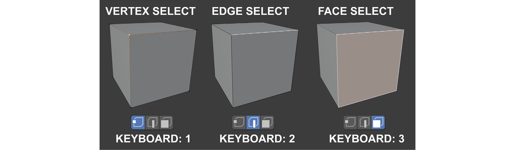
Figure 1.5 – How to select mesh components
To select any of these components for our tutorials, we will use the Box Select tool from the toolbar. Once selected, you can make a variety of edits. We will discuss how to do this later.
To toggle back to Object Mode (and leave Edit Mode), just press Tab.
- Selecting linked mesh components: There are times when you may want to select linked (connected) parts of your mesh that are a continuous mesh surface. Position your mouse cursor over the part you want to select and use the Ctrl + L shortcut. To deselect linked (connected) mesh components under your mouse cursor, press Shift + L.
In this section, you learned how to select and deselect various items and/or their components.
In the next section, we will explore the concepts of axes and transform orientations in Blender.
Axes and transform orientations
What are axes? In 3D graphics, an axis is an imaginary line in a 3D space that defines a direction. There are three axes – X, Y, and Z – that correspond to the left/right (X), front/back (Y), and up/down (Z) directional lines, as shown in the following diagram.
Axes have both a positive and a negative direction and are colored to make them easier to visually identify. The X-axis is red, the Y-axis is green, and the Z-axis is blue. In Blender and Unreal Engine (UE), the up direction is in the positive direction of the Z-axis:
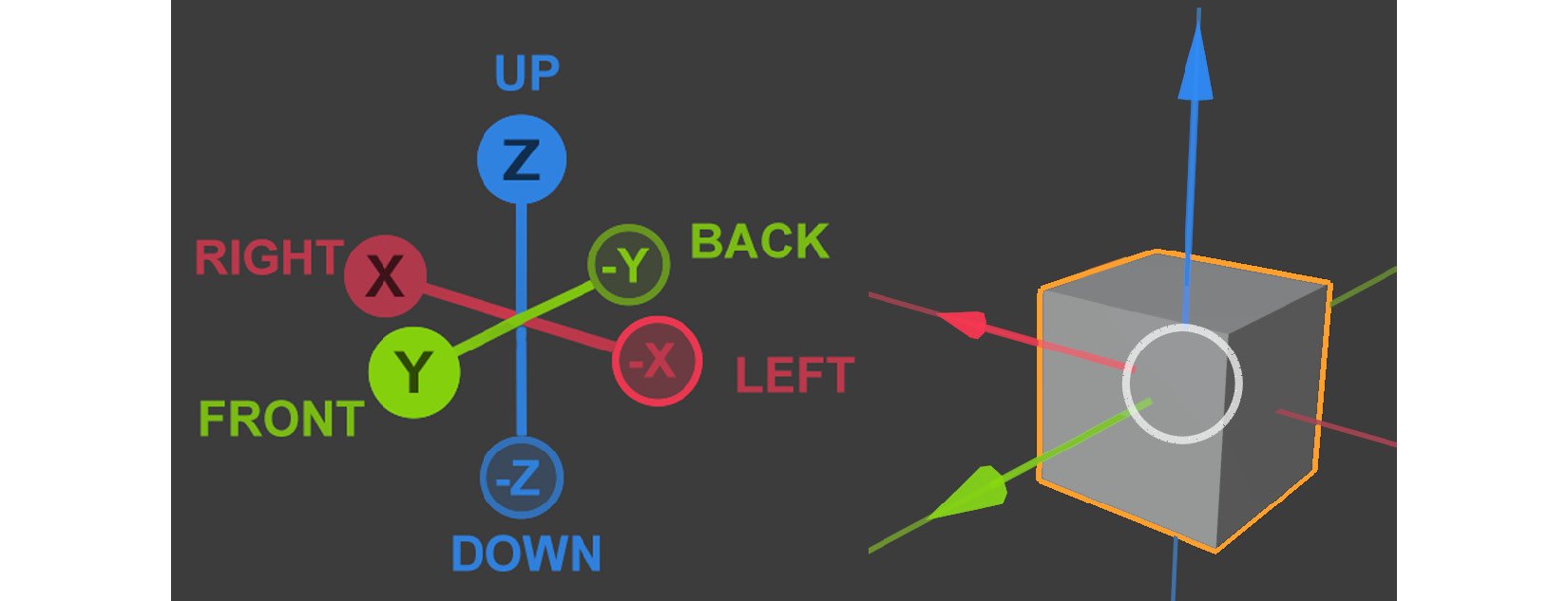
Figure 1.6 – (A) Blender's three axes: X, Y, and Z; (B) The cube serves as a reference to show how the three axes will appear on a 3D cube mesh
Now that you know what axes are, let's take a quick look at some of the other concepts you need to understand:
- Transform: Transforming an object/item means to move, rotate, or scale it. When you transform an object, you are automatically using the object's axes and the axes' orientation to transform it.
- Orientation: This describes the direction of the axes. The orientation of the axes changes, depending on the type of Transform Orientation that you choose. In Figure 1.7, you can see that the orientation of the red, green, and blue arrows (called the Object Gizmo) changes from Figure 1.7, part A, to Figure 1.7, part B.
Note
We will cover the Object Gizmo in more depth in a later section.
- Transform Orientation: This changes the behavior of transformations. In other words, the way that you transform/manipulate an object will change, depending on which Transform Orientation you choose to use. In this chapter, we will cover two of these Transform Orientation options – the Global axis and the Local axis.
To change your transform orientation using the Transform Orientations menu (drop-down menu), go to the Header bar and look for the icon with the word Global next to it. This menu is shown near the top area of the following screenshot:
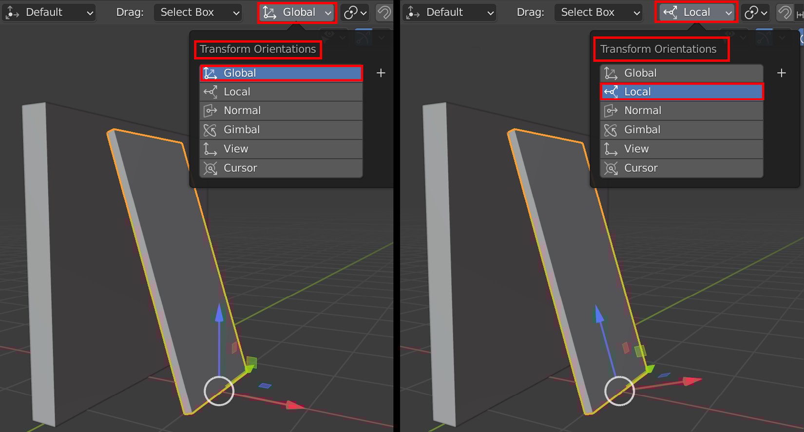
Figure 1.7 – (A) Using Global (Transform Orientations); (B) Using Local (Transform Orientations)
Let's take a quick look at the difference between the Global axis and the Local axis:
- Global: The orientation of the Global axis is aligned to the world/scene. In Figure 1.7, part A, I selected the Global axis Transform Orientation for the orange-outlined box. The Global axis Transform Orientation is set as the default for all objects/items in Blender. The orientation of the Global axis is fixed and cannot be changed. All items in Blender can share the same Global axis since it is the axis of the world/scene.
- Local: Each object/item in Blender has a Local axis that is unique to the object/item/component. When the object is transformed, the Local axis will follow along. In Figure 1.7, part B, I selected the Local axis, and you can see that the axes of the orange-outlined box are following a different orientation than when we used the Global axis. Local axes are adjustable, unlike the Global axes.
You've just learned about the concepts of axes, transforms, orientations, and how to switch between the Global axis and the Local axis using the Transform Orientation menu.
In the next section, we will go over the shortcuts that can be used to transform your objects. We will also explore how to use shortcuts to switch between the Global and Local axis Transform Orientation, to speed up your workflow.
Lastly, we will explore how to use Object Gizmos as another way to transform your objects.
Manipulating objects or their components
We can manipulate objects/components by either using shortcuts or Object Gizmos. We will explore how to use both these options now. Let's start by showing you how to manipulate using shortcuts.
Using shortcuts to manipulate objects/components
Let's look at the shortcuts for moving, rotating, and scaling objects/components:
- Move: Use the G shortcut to move your selected item up, down, left, or right (perpendicular to your current viewing angle). To constrain the movement to a Global axis, hold down the X, Y, or Z key (the axes' name keys) while using this shortcut. If you press the same axis key (X, Y, or Z) a second time, it will toggle a constrain for your movement to a Local axis.
- Rotate: Use the R shortcut to rotate your selected item in either a clockwise or anti-clockwise direction (perpendicular to your current viewing angle). The item will use the object's origin (as shown in Figure 1.3) as the pivot point for the rotation. To constrain the rotation to a Global axis, hold down the X, Y, or Z key (the axes' name keys) while using this shortcut. If you press the same axis (X, Y, or Z) a second time, it will toggle a constrain for your rotation to a Local axis.
- Scale: Use the S shortcut to scale your selected item up or down. The item will use the object origin (as shown in Figure 1.3) as the center for scaling. To constrain the scaling to a Global axis, hold down the X, Y, or Z key (the axes' name keys) while using this shortcut. If you press the same axis (X, Y, or Z) a second time, it will toggle a constrain for your scaling to a Local axis.
You've just learned how to use shortcuts to transform objects and their components and other items. You've also learned that you can constrain these transforms by using the X, Y, or Z keys (the axes' name keys) and that you can switch between the Global and Local axis by pressing these keys once for the Global axis, and twice for the Local axis.
In the next section, we will learn how to use Object Gizmos to transform/manipulate objects, components, or items.
Using Object Gizmos to manipulate objects/components
What are Object Gizmos? They are transform (manipulation) tools that appear in the 3D Viewport and are overlayed on the selected item when you choose one of the three manipulation modes (move, rotate, or scale) from the toolbar, as shown in the following screenshot.
Object Gizmos offer an alternative way (another alternative to using shortcuts) to transform/manipulate objects or their components in the scene. The benefit of using Object Gizmos is that you can constrain the movement or scale to two of the three axes during a transform (constrained to a two-dimensional plane). This isn't possible when using shortcuts:
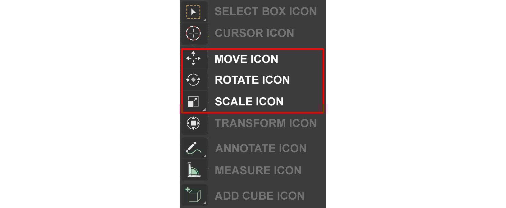
Figure 1.8 – The toolbar, with descriptions of the icons next to them. I have highlighted the manipulation modes
Let's take a look at how we can activate any of the three Object Gizmos
- Move: Use the Space bar + G shortcut or click on MOVE ICON in the toolbar, as shown in the preceding screenshot, to move with the Move Object Gizmo.
- Rotate: Use the Space bar + R shortcut or click on ROTATE ICON in the toolbar, as shown in the preceding screenshot, to rotate with the Rotate Object Gizmo.
- Scale: Use the Space bar + S shortcut or click on SCALE ICON in the toolbar, as shown in the preceding screenshot, to scale with the Scale Object Gizmo.
Once you have selected a Transform mode (move, rotate, or scale), the Object Gizmos will be overlayed over your item, as shown in the following diagram:
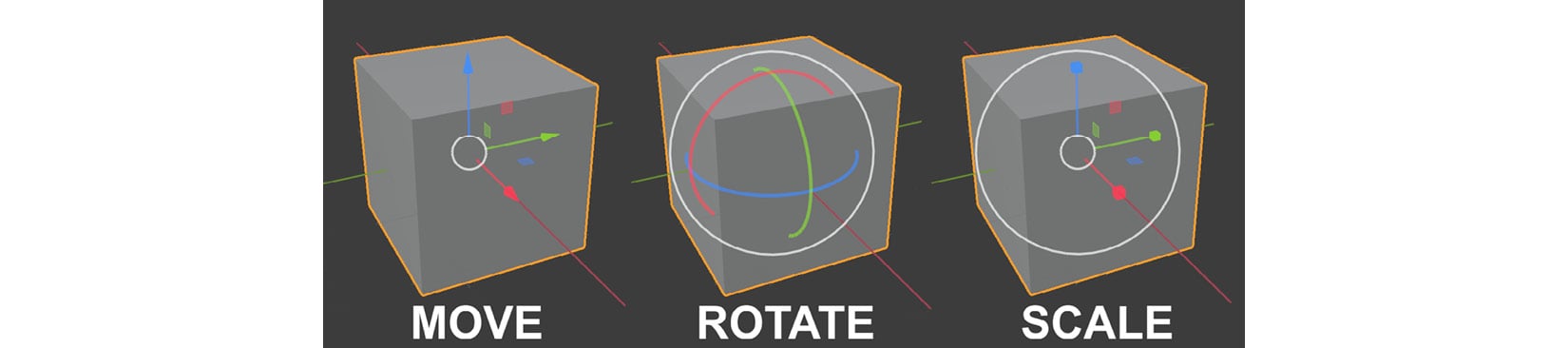
Figure 1.9 – The Object Gizmos overlaid over a 3D cube model for move, rotate, or scale
Inside the Move Object Gizmos, you can see that there are red, green, and blue arrows that point in three directions. These three directions represent the three axes. The red arrow represents the X-axis, the green arrow represents the Y-axis, and the blue arrow represents the Z-axis.
For example, if you want to move the cube in the X-axis direction, you should left-click and hold the red arrow and then move the mouse. This will move the cube in the X-axis direction. Then, you can release the mouse again when you want to stop moving it.
The small white circle in the middle of the Move Object Gizmo is to move the object in any direction that is perpendicular to your current viewing angle.
If you manipulate the small red, green, and blue planes near the center of the gizmo, it will constrain the movement to two of your chosen axes during a transform. For example, if you manipulate the red plane, the model's movement would be constrained to the Y-axis and Z-axis simultaneously. In other words, it would be constrained to a two-dimensional plane.
The Rotate Object Gizmo has red, green, and blue colored curves. The red curve represents the X-axis, the blue curve represents the Y-axis, and the green curve represents the Z-axis. Use these curves to rotate the selected object. The white circle that encompasses the colored curves allows free rotation in any direction that is perpendicular to your current viewing angle.
The Scale Object Gizmo has red, green, and blue lines with square endpoints that will scale the selected object in the X, Y, or Z directions, respectively. There are two white circles on this gizmo, and you can use either of them to scale freely on all three axes simultaneously. If you manipulate the small red, green, and blue planes near the center of the gizmo, it will constrain the scaling to two of your chosen axes during a transform (constrained to a two-dimensional plane).
In this section, you learned how to manipulate items/components using three types of object gizmos that are available.
In the next section, we will explore how to change the way that Blender displays meshes and other items by using different View Mode options.
View Mode
View Mode (or Viewport Shading Mode) is used to display an item/component in the 3D Viewport.
The different options in View Mode are Solid View Mode, X-Ray View Mode, and Wireframe Viewport Shading Mode:
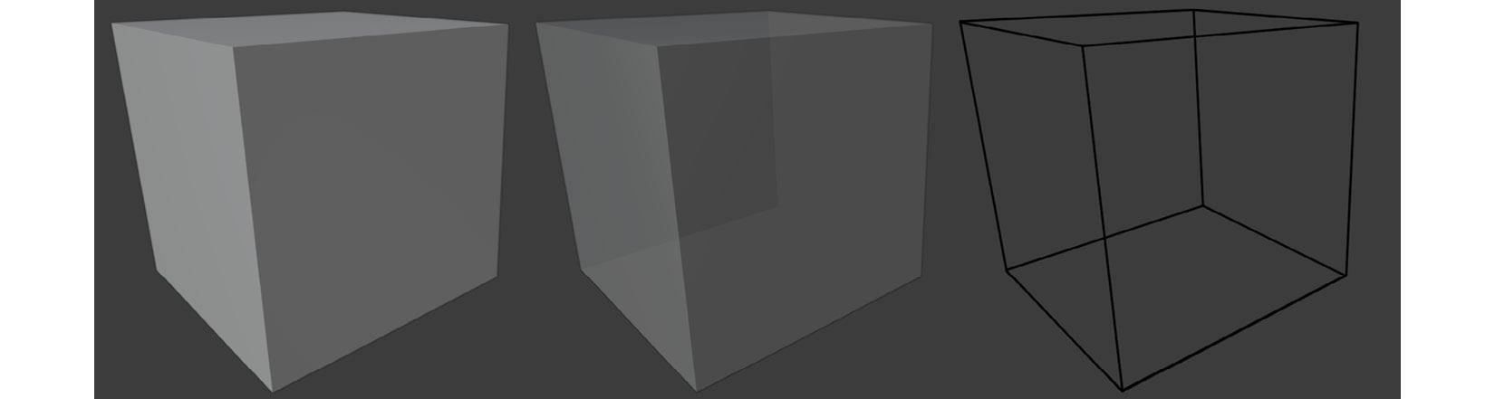
Figure 1.10 – Viewport Shading Modes – (A) Solid View Mode; (B) X-Ray View Mode; (C) Wireframe Viewport Shading Mode
Note
Solid View Mode is the default Viewport Shading Mode. In this mode, when you use the select box to select the components of a mesh, it will only select the components that are facing your current view (visible components). When you want to select mesh components on the other side of your current object (not visible in Solid View Mode), you need to activate either X-Ray View Mode or Wireframe Viewport Shading Mode.
The following shortcuts are used to toggle the View Mode options:
- Use Alt + Z to toggle X-Ray View Mode.
- Use Shift + Z to toggle Wireframe View Mode.
- Use Z to toggle the Shading Pie Menu, which contains the Solid, Wireframe and X-Ray Viewport shading modes.
You have just learned about the different Viewport Shading Modes and why these are essential when creating 3D assets. You need these to switch between Solid View Mode, X-Ray View Mode, and Wireframe Viewport Shading Mode to select mesh components on the non-visible side of your model.
This also concludes the Introducing Blender section. You now understand the user interface, Viewport navigation, how to select and deselect, and how to manipulate items with object gizmos.
In the next section, we will explore the 3D modeling tools that we will use in the next four chapters.