
Using masks within a material
Our first goal in this chapter is going to be the replication of a complex material graph. Shaders in Unreal usually depict more than one real-life substance, so it’s key for us to have a way to control which areas of a model are rendered using the different effects programmed in a given material. This is where masks come in: textures that we can use to separate (or mask!) the effects that we want to apply to a specific area of the models with which we are working. We’ll do that using a small wooden toy tank, a prop that could very well be one of the assets that a 3D artist would have to adjust as part of their day-to-day responsibilities.
Getting ready
We’ve included a small scene that you can use as a starting point for this recipe—it’s called 02_01_ Start, and it includes all of the basic assets that you will need to follow along. As you’ll be able to see for yourself, there’s a small toy tank that has two UV channels located at the center of the level. UVs are the link between the 2D textures that we want to apply to a model and the 3D geometry itself, as they are a map that correlates the vertex positions in 2D and 3D space. The first of those UVs indicates how textures should be applied to 3D models, whereas the second one is used to store the lightmap data the engine calculates when using static lighting.
If you decide to use your own 3D models, please ensure that they have well-laid-out UVs, as we are going to be working with them to mask certain areas of the objects.
Tip
We are going to be working with small objects in this recipe, and that could prove tricky when we zoom close to them—the camera might cut through the geometry, something known as clipping. You can change the behavior of the camera by opening the Project Settings panel and looking inside the Engine | General Settings | Settings section, where you’ll find a setting called Near Clip Plane, which can be adjusted to sort out this issue. Using a value of 1 will alleviate this issue, but remember to restart the editor in order for the changes to be implemented.
How to do it…
The goal of this recipe is going to be quite a straightforward one: to apply different real-world materials to certain parts of the model with which we are going to be working using only a single shader. We’ll start that journey by creating a new material that we can apply to the main toy tank model that you can see at the center of the screen. This is all provided you are working with the scene I mentioned in the Getting ready section; if not, think of the next steps as the ones you’ll also need to implement to texture one of your own assets. So:
- Create a new material, which you can name M_ToyTank, and apply it to the toy model.
- Open the Static Mesh Editor for the toy tank model, by selecting the asset from the level and double-clicking on the Static Mesh thumbnail present in the Details panel.
- Visualize the UVs of the material by clicking on the UV | UV Channel 0 option within the Static Mesh Editor, as seen in the next screenshot:
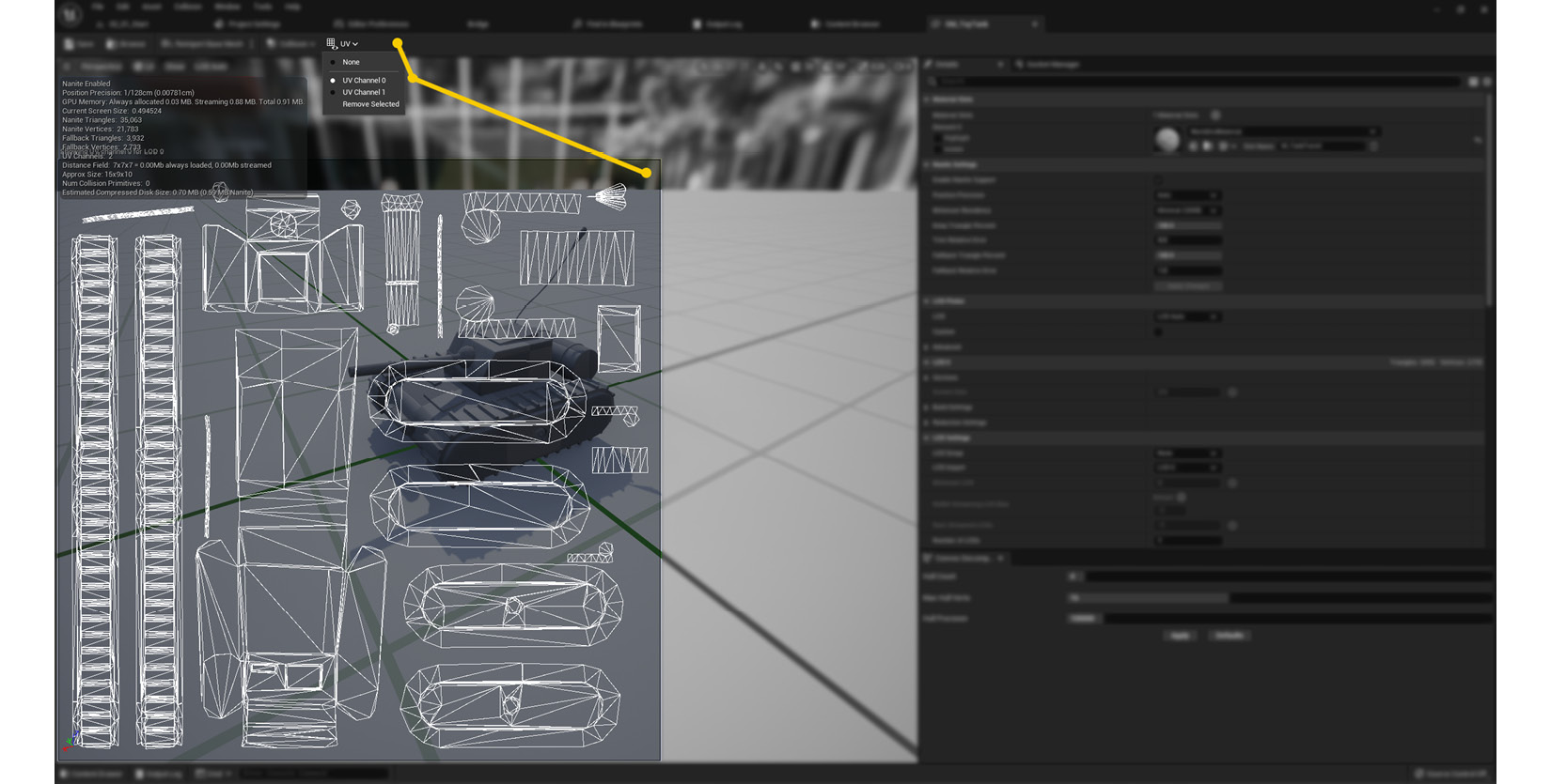
Figure 2.2 – Location of the UV visualizer options within the Static Mesh Editor
As seen in Figure 2.2, the UV map of the toy tank model is comprised of several islands. These are areas that contain connected vertices that correspond to different parts of the 3D mesh—the body, the tracks, the barrel, the antenna, and all of the polygons that make up the tank. We want to treat some of those areas differently, applying unique textures depending on what we would like to see on those parts, such as on the main body or the barrel. To do so, we will need to create masks that cover the selected parts we want to treat differently. The project includes one such texture designed specifically for this toy tank asset, which we’ll use in the following steps. If you want to use your own 3D models, make sure that their UVs are properly unwrapped and that you create a similar mask that covers the areas you want to separate.
Tip
You can always adjust the models provided with this project by exporting them out of Unreal and importing them into your favorite Digital Content Creation (DCC) software package. To do that, right-click on the asset within the Content Browser and select Asset Actions | Export.
- Open our newly created material and create a Texture Sample node within it (right-click and then select Texture Sample, or hold down the T key and click anywhere inside the graph).
- Assign the T_TankMasks texture (located within Content | Assets | Chapter 02 | 02_01) to the previous Texture Sample node (or your own masking image if working with your own assets).
- Create two Constant3Vector nodes and select whichever color you want under their color selection wheel. Make sure they are different from one another, though!
- Next, create a Lerp node—that strange word is short for linear interpolation, and it lets us blend between different assets according to the masks that we connect to the Alpha pin.
- Connect the R (red) channel of the T_TankMasks asset to the Alpha pin of the new Lerp node.
- Connect each of the Constant3Vectors to the A and B pins of the Lerp node.
- Create another Lerp node and a third Constant3Vector.
- Connect the B (blue) channel of the T_TankMasks texture to the Alpha pin of the new Lerp node, and the new Constant3Vector to the B pin.
- Connect the output of the Lerp node we created in step 7 (the first of the two we should have by now) to the A slot of the new Lerp node.
- Assign the material to the tank in the main scene. The material graph should look something like this at the moment:
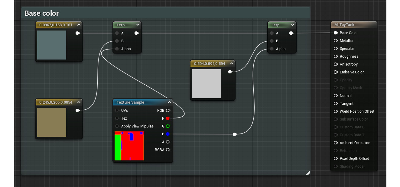
Figure 2.3 – The current state of the material graph
We’ve managed to isolate certain areas of the toy tank model thanks to the use of the previous mask, which is one of our main goals for this recipe. We now need to apply this technique to the Metallic and Roughness parameters of the material, just so we can control those independently.
- Copy all the previous nodes and paste them twice—we’ll need one copy to connect to the Roughness slot and a different one that will drive the Metallic attribute.
- In the new copies, replace the Constant3Vector nodes with simple Constant ones. We don’t need an RGB value to specify the Metallic and Roughness properties, so that’s why we only need standard Constant nodes this time around.
- Assign custom values to the new Constant nodes you defined in the previous step. Remember what we already know about these parameters: a value of 0 in the Roughness slot means that the material has very clear reflections, while a value of 1 means the exact opposite. Similarly, a value of 1 connected to the Metallic node means that the material is indeed metal, while 0 determines that it is not. I’ve chosen a value of 0 for the first two Constant nodes and a value of 1 for the third one. Let’s now review these new sections of the graph:
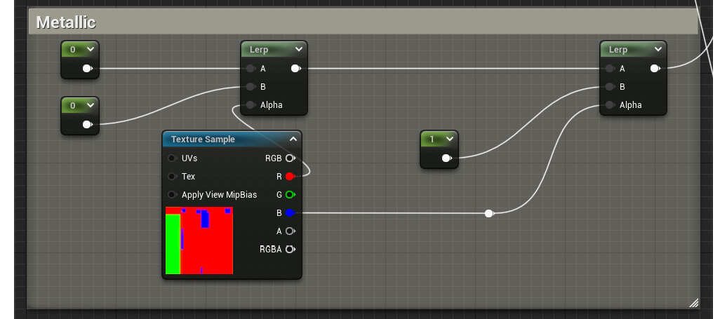
Figure 2.4 – A look at the new Metallic section of the material, which is a duplicate of the Roughness one
Finally, think about tidying things up by creating comments, which is a way to group the different sections of the material graph together. This is done by selecting all of the nodes that you want to group and pressing the C key on your keyboard. This keeps things organized, which is very important no matter whether you work with others or whether you revisit your own work. You saw this in action in the previous screenshot with the colored outlines around the nodes. Having said that, let’s take a final look at the model, calling it a day!
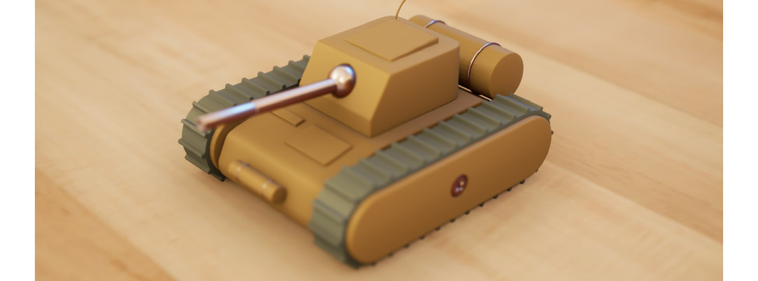
Figure 2.5 – The toy tank with the new material applied to it
How it works…
In essence, the textures that we’ve used as masks are images that contain a black-and-white picture stored in each of the files’ RGB channels. This is something that might not be that well known, but the files that store the images that we can see on our computers are actually made out of three or four different channels—one containing the information for the red pixels, another for the green ones, and yet one more for the blue tones, with an extra optional one called Alpha where certain file types store the transparency values. Those channels mimic the composition of modern flat panel displays, which operate by adjusting the intensity received by the three lights (red, green, and blue) used to represent a pixel.
Seeing as masks only contain black-and-white information, one technique that many artists use is to encode that data in each of the channels present in a given texture. This is what we saw in this recipe when we used the T_TankMasks texture, an image that contains different black-and-white values in each of its RGB channels. We can store up to three or four masks in each picture using this technique—one per available channel, depending on the file type. You can see an example of this in the following screenshot:
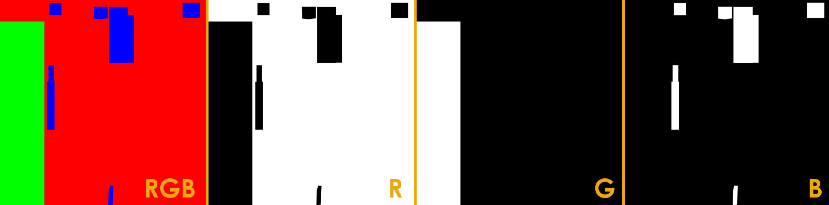
Figure 2.6 – The texture used for masking purposes and the information stored in each of the RGB channels
The Lerp node, which we’ve also seen in this recipe, manages to blend two inputs (called A and B) according to the values that we provide in its Alpha input pin. This last pin accepts any value situated in the 0 to 1 range and is used to determine how much of the two A and B input pins are shown: a value of 0 means that only the information provided to the A pin is used, while a value of 1 has the opposite effect—only the B pin is shown. A more interesting effect happens when we provide a value in between, such as 0.25, which would mean that both the information in the A and in the B pin is used—75% of A and 25% of B in particular. This is also the reason why we used the previous mask with this node: as it contained only black-and-white values in each of its RGB channels, we could use that information to selectively apply different effects to certain parts of the models.
Using masks to drive the appearance of a material is often preferable to using multiple materials on a model. This is because of the way that the rendering pipeline works behind the scenes—without getting too technical, we could say that each new material that a model has makes it more expensive to render. It’s best to be aware of this whenever we work on larger projects!
See also
We’ve seen how to use masks to drive the appearance of a material in this recipe, but what if we want to achieve the same results using colors instead? This is a technique that has seen widespread use in other 3D programs, and even though it’s not as simple or computationally cheap as the masking solution we’ve just seen in Unreal, it is a handy feature that you might want to explore in the future. The only requirement is to have a color texture where each individual shade is used to mask the area we want to operate on, as you can see in the following screenshot:
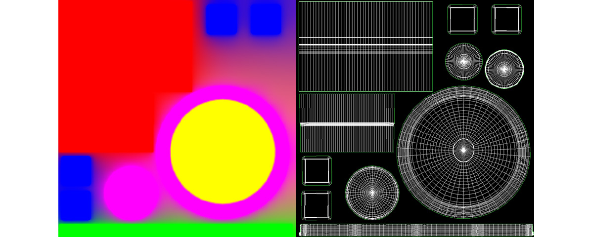
Figure 2.7 – Another texture used for masking, where each color is meant to separate different materials
The idea is to isolate a color from the mask in order to drive the appearance of a material. If this technique interests you, you can read more about it here: https://answers.unrealengine.com/questions/191185/how-to-mask-a-singlecolor.html.
Finally, there are more examples of masks being used in other assets that you might want to check. We can find some within the Sample Content node, inside the following folder: Starter Content | Props | Materials. Shaders such as M_Door or M_Lamp have been created according to the masking methodology explained in this chapter. On top of that, why not try to come up with your own masks for the 3D models that you use? That is a great way to look at UVs, 3D models, image-editing software, and Unreal. Be sure to try it out!