
Understanding Advanced Printing Settings
Most of the time, the default print settings are more than enough to get good results for our objects. However, sometimes, for example, when printing exotic materials or when experimenting with complex parts, we may have to tune them a little.
Unfortunately, additive manufacturing is a rather complex process, and FDM printers have a lot of settings we must at least understand in order to master the technology.
In this chapter, we will dive straight into printing settings, reviewing the most important ones that every beginner should learn. The goal is to show, as much as possible, how different settings can influence the printing results.
So, in this chapter, we will cover the following topics:
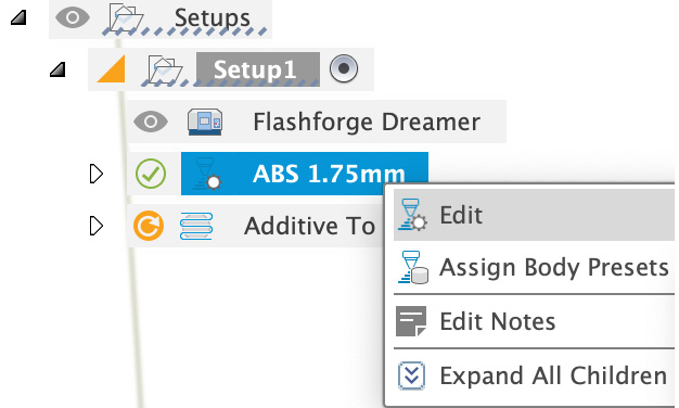
- Creating a new printing preset
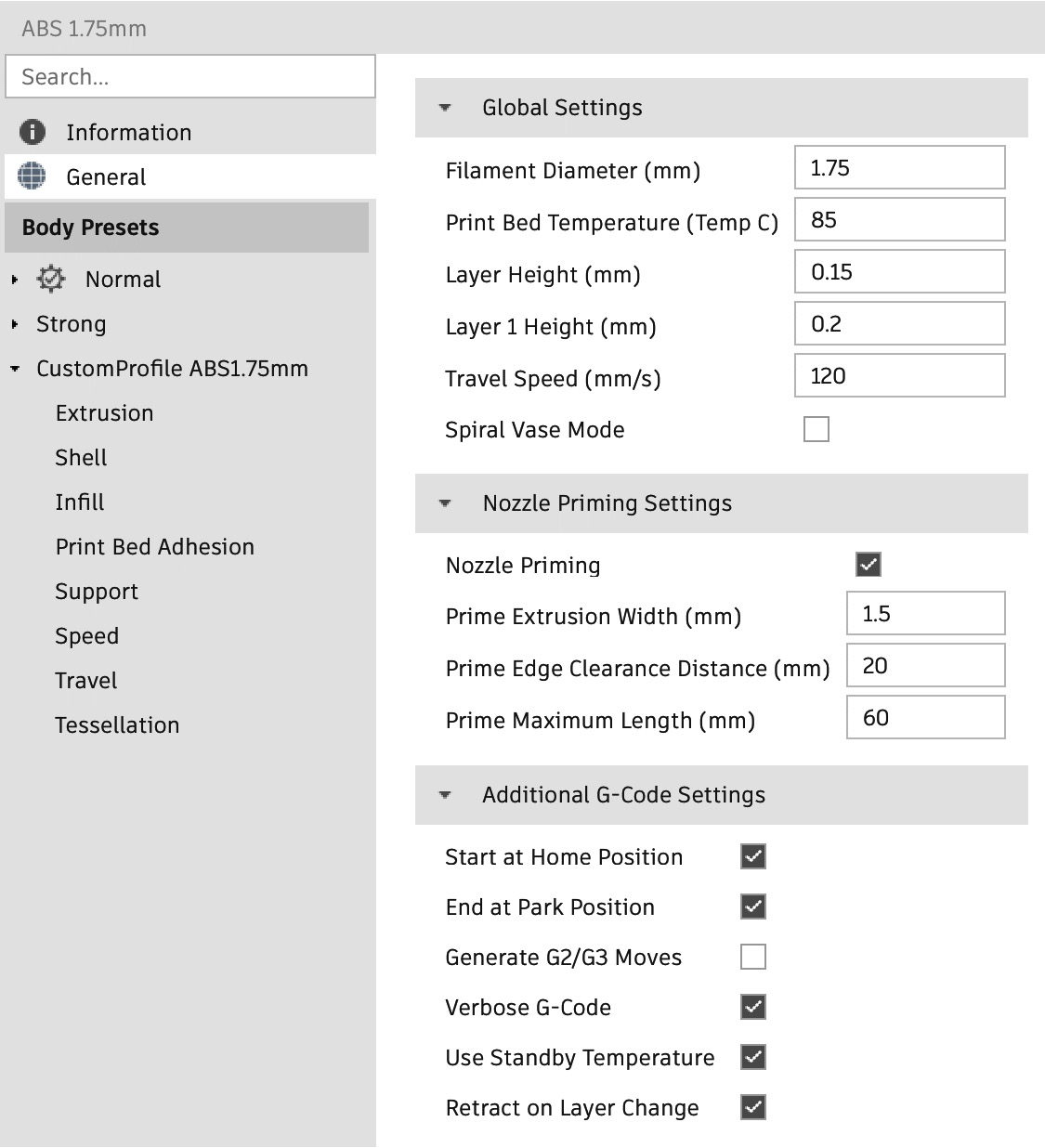
- Understanding general parameters
- Understanding extruder parameters
- Understanding shell parameters
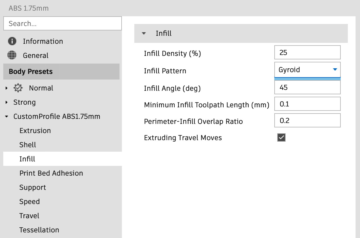
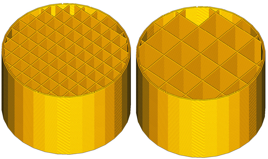
- Understanding infill parameters
- Understanding print bed adhesion
- Understanding support...