Reader small image

You're reading from  Making Your CAM Journey Easier with Fusion 360

Product typeBook
Published inMar 2023
PublisherPackt
ISBN-139781804612576
Edition1st Edition
Concepts
Right arrow
Author (1)
Fabrizio Cimò
Fabrizio Cimò
author image
Fabrizio Cimò

Fabrizio Cimò is an Italian engineer who has always had a passion for the world of 3D graphics and design. During his first degree in industrial design, he started uploading video lessons covering 3D modeling tools such as Rhinoceros, Blender, and Fusion 360 on his YouTube channel. Sometime later, Autodesk noticed his work and asked him to keep promoting Fusion 360 as an official student ambassador. During this time, he also joined Dynamis PRC, a racing team from Milano PT competing in the Formula SAE championship; thanks to this experience and his avid curiosity, he improved his knowledge of the manufacturing world. Today, Fabrizio works as a machine designer for an important company in the laser-cutting sector.
Read more about Fabrizio Cimò

Right arrow

Implementing Our First Milling Operations

In this chapter, we will implement all the cutting operations to complete the first stock placement for our example part. We won’t jump directly to complex 3D operations (which will be covered in Chapter 10) but rather, we will start from the most common 2D milling strategies of face milling and pocket milling.

We will learn how to set up the main 2D milling operations and how to calculate the cutting parameters using CoroPlus. While doing this, we will try to have a critical point of view on the proposed solution, learning how to optimize the machining time and reducing the number of tool changes in our CAM program.

Not only we will learn how to set up milling operations using an online calculator, but we will also calculate the cutting parameters by ourselves (step by step), using the equations introduced in Chapter 6.

The overall goal of this chapter is to get you used to the milling environment of Fusion 360 before moving...

Technical requirements

This chapter is a bit more advanced than the previous ones, so I strongly advise that you read and study all the chapters about milling and turning theory so far. Some concepts won’t be explained again in the hope that you are already a bit more confident with the basics of CAM interfaces and machining operations.

Also, as we will be using CoroPlus for cutting parameters as well as solving equations, a calculator or an Excel sheet may be required.

Face milling

As described in Chapter 8 (as shown in Figure 8.2), the first milling operation we have to implement is facing the top side of the stock; here, we have to remove a layer of 1.5 millimeters of our part.

At the moment, the stock is 45 mm tall, and we need to bring it down to 42 mm by removing 1.5 mm from both the top and bottom face, to have a good surface quality. As discussed in Chapter 6, the best strategy to remove a flat layer of material is face milling, a fundamental milling operation that allows us to machine flat areas.

Note

Depending on the quality of the stock, we may need to increase the amount of extra material to remove for a successful facing operation. The more the stock is bent or irregular, the more material we shall remove, and the bigger the stock shall be.

Let’s begin with finding the right tool and parameters using our trusty Sandvik CoroPlus.

Using CoroPlus to find the best tool for face milling and shoulder milling

We have...

Shoulder milling

For our second milling operation – shoulder milling – we will machine the circular slot in the center of our part:

Figure 9.16: The slot profile

Figure 9.16: The slot profile

It has a diameter of 80 millimeters and a depth of 10 millimeters. As mentioned before, we will use the same tool already used for the first facing operation.

Calculating the cutting parameters by hand

Before launching the command on Fusion 360, we should evaluate the cutting parameters. However, the bad news is that this time, instead of using CoroPlus, we will try to calculate them on our own. Be sure of this – it will be a bit trickier but way more satisfying!

First of all, we should understand our machine specifications:

  • We will use a Haas VF-1
  • The maximum cutting power is around 22.4 kW
  • Its maximum rated spindle speed is 8,100 RPM
  • The maximum torque is obtained at 2,000 RPM with a value of 122 Nm

These values will be needed to check...

Drilling

We fully covered the drilling operation in Chapter 5, for our turning example. The command is the same for milling as well; therefore, we will skip a long introduction regarding the panels and just cover the required settings for the example.

So, as before, let’s look at the Tool tab first.

The Tool tab

Inside this panel, we can specify the tool to use and the main cutting parameters:

Figure 9.23: Drilling’s Tool tab

Figure 9.23: Drilling’s Tool tab

The first thing we have to set is the cutting tool, which for a drilling operation is a drill bit. Since the holes will need to be threaded, we have to create a pilot with a certain diameter. The thread we will have to tap is an M8; therefore, the pilot hole shall have a diameter of 6.8 mm.

So, as you can see from the preceding screenshot, we have to pick a drill bit with a diameter of 6.8 mm.

Now that we have chosen the right tool, we can focus on the cutting parameters. Clicking on the drop-down menu...

Tapping

There is not a dedicated command for tapping, so we have to use the drilling command instead. Since we just reviewed the command for drilling, we will just cover the important settings for tapping.

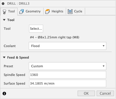
We have to thread the first 20 millimeters of the holes with an ISO M8 x 1.25 thread. To do this, we have to choose a tap with the same pitch and diameter. Luckily, there are many tapping tools at our disposal in the default tool library; therefore, we don’t have to create or import a new tool.

Figure 9.28: Drilling’s Tool tab (used for Tapping)

Figure 9.28: Drilling’s Tool tab (used for Tapping)

CoroPlus suggests a Spindle Speed setting of 1360 RPM, resulting in a Surface Speed setting of 34.1805 m/min, so all we have to do is input those values inside the panel.

Then, we have to specify all of the holes to machine using the Geometry panel; we won’t repeat this procedure, since it’s identical to how we drilled the pilot holes in the last section.

However, we should...

Summary

That concludes this chapter. I hope that the extra effort required for the equations was worth it; now, we don’t really need online tools anymore (even if they are still valuable).

In summary, we first set up face milling using CoroPlus. Then, we decided to change the suggested cutting tool and opt for one capable of machining the round pocket in the center of the stock.

After the first facing operation was implemented in Fusion 360, we moved to the circular slot in the center of the part and calculated all the required cutting parameters, using the milling equations.

After completing the milling operations, we moved to drilling and tapping. First, we found out how to drill holes using the same drilling command already introduced in Chapter 5, but this time, we mentioned a chip evacuation technique called pecking. After drilling the holes, we moved on to tapping and found out how to set the thread length and check for errors in the final simulation.

In this...

lock icon
The rest of the chapter is locked
You have been reading a chapter from
Making Your CAM Journey Easier with Fusion 360
Published in: Mar 2023Publisher: PacktISBN-13: 9781804612576
Register for a free Packt account to unlock a world of extra content!
A free Packt account unlocks extra newsletters, articles, discounted offers, and much more. Start advancing your knowledge today.
undefined
Unlock this book and the full library FREE for 7 days
Get unlimited access to 7000+ expert-authored eBooks and videos courses covering every tech area you can think of
Renews at $15.99/month. Cancel anytime

Author (1)

author image
Fabrizio Cimò

Fabrizio Cimò is an Italian engineer who has always had a passion for the world of 3D graphics and design. During his first degree in industrial design, he started uploading video lessons covering 3D modeling tools such as Rhinoceros, Blender, and Fusion 360 on his YouTube channel. Sometime later, Autodesk noticed his work and asked him to keep promoting Fusion 360 as an official student ambassador. During this time, he also joined Dynamis PRC, a racing team from Milano PT competing in the Formula SAE championship; thanks to this experience and his avid curiosity, he improved his knowledge of the manufacturing world. Today, Fabrizio works as a machine designer for an important company in the laser-cutting sector.
Read more about Fabrizio Cimò