
Printing Our First Part
Now that we’ve covered the general theory behind FDM additive manufacturing, we can move on to Fusion 360 and its CAM module.
In this chapter, we will approach an example part, starting from the setup and then reviewing the whole process. The goal of this chapter is to provide you with all the tools needed to create a G-code file to export to a 3D printer.
In this chapter, we will cover the following topics:
- Presenting the model
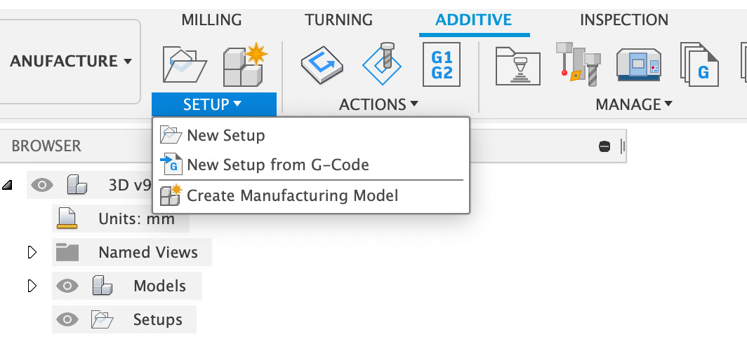
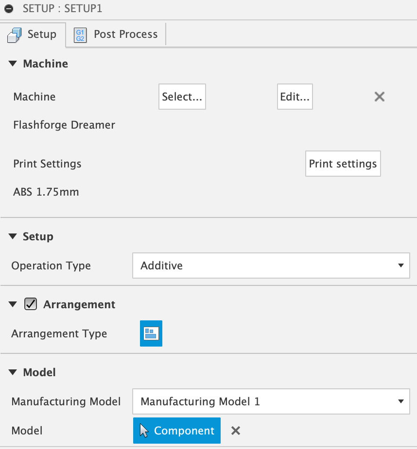
- Creating a new printing setup
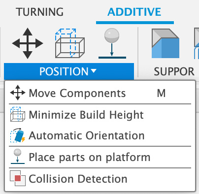
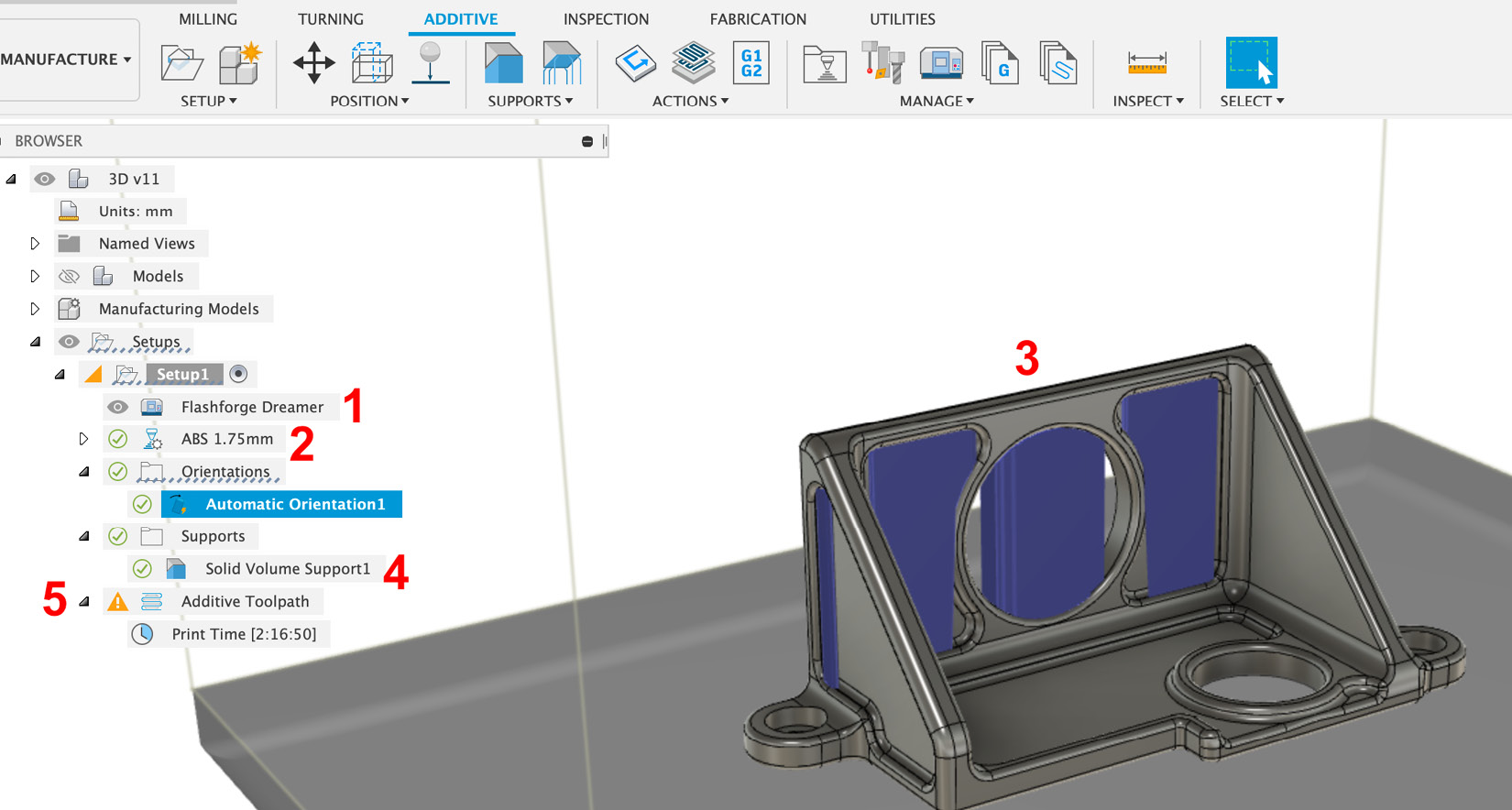
- Orienting the model onto the build platform
- Generating the support structures
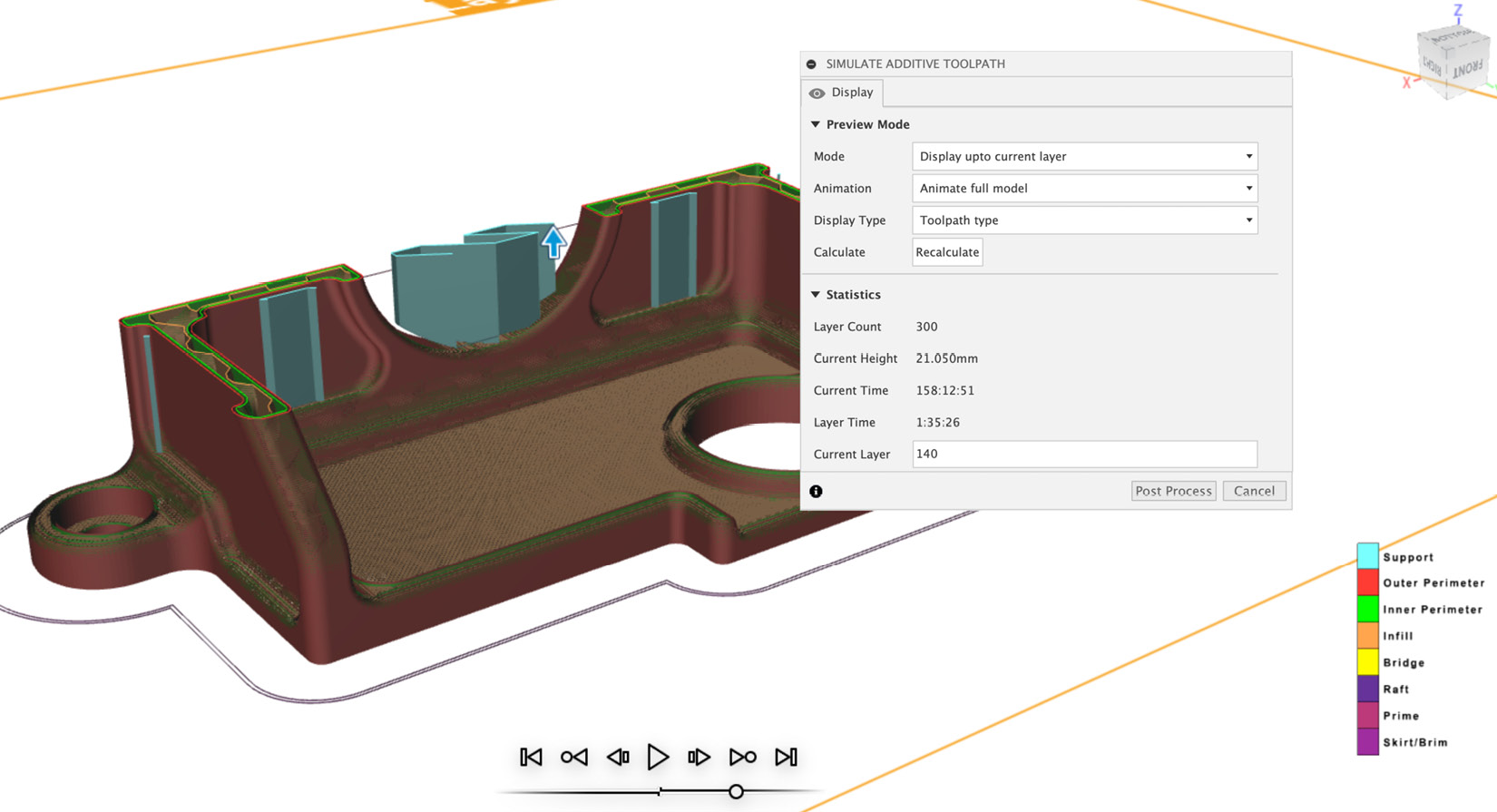
- Simulating the toolpath
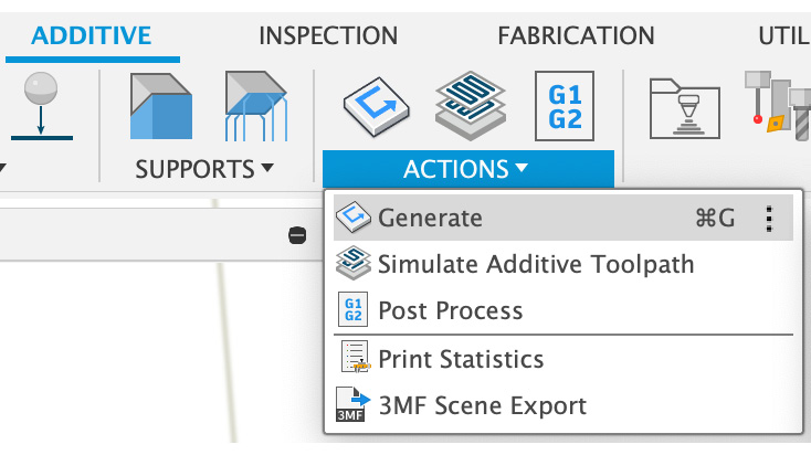
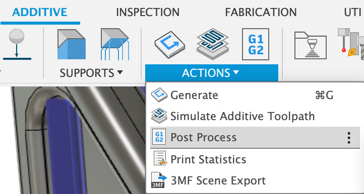
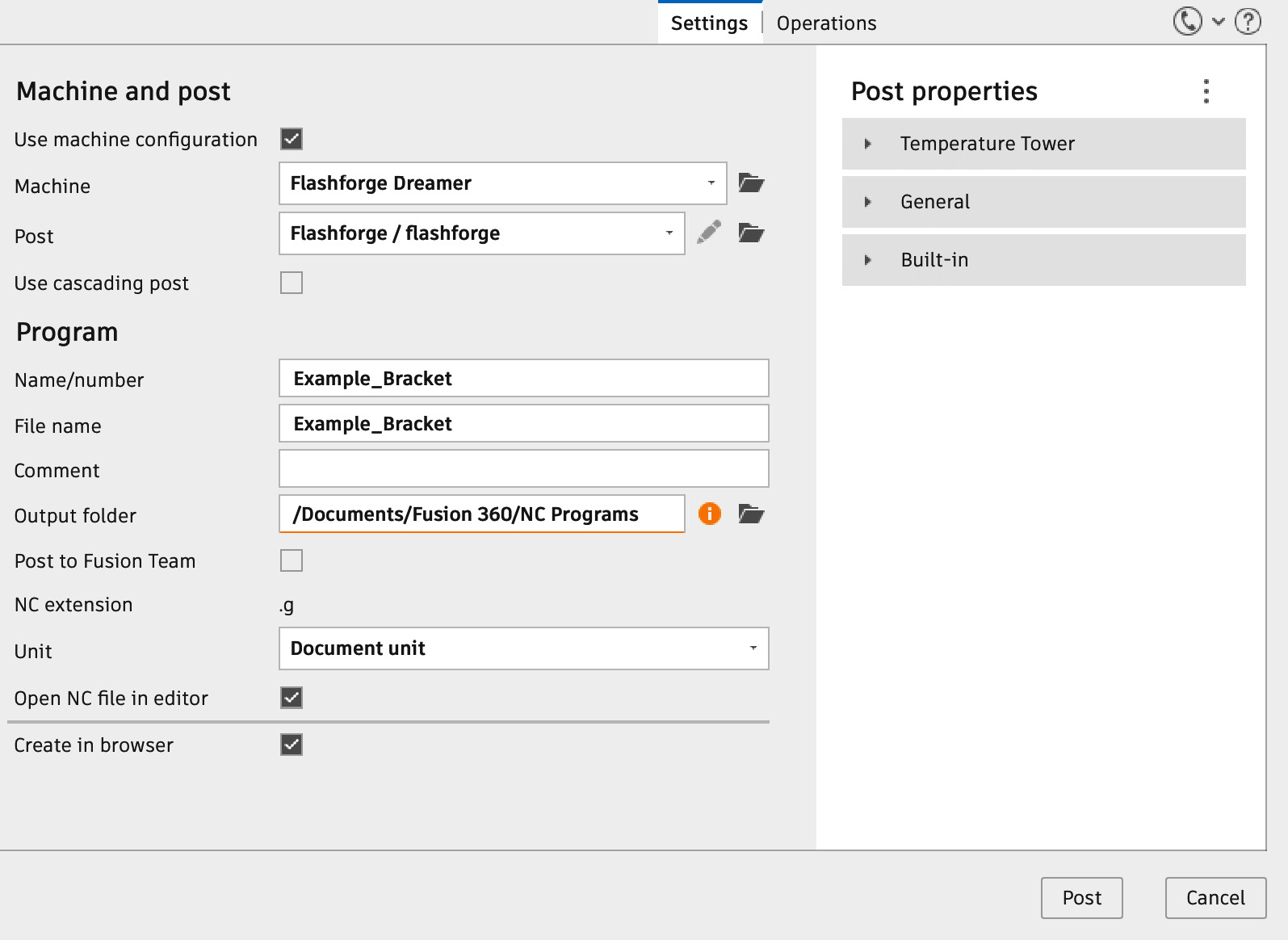
- Using the post-processor