
Machining the Second Placement
This chapter directly follows on from the previous one since we will start right where we left off before. Now that we have completed all the milling operations on the first placement (the first setup), we can focus on the second placement by implementing all the remaining operations that will result in the final shape of the part.
What we are about to do is clearly depicted in the following figure:
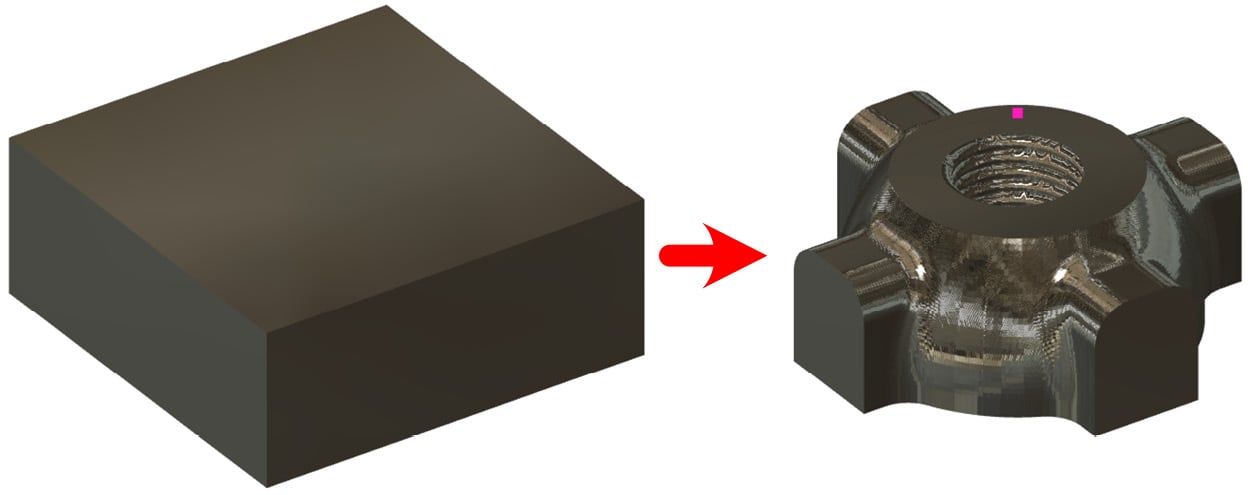
Figure 10.1: The second placement
The partially machined stock has now been flipped and installed onto the fixture we mentioned in Chapter 8. With this second placement, we will machine the opposite side of the part. We will now cover every remaining cutting operation one by one.
The goal of this chapter is to introduce more complex operations than those found in Chapter 9, leading you closer and closer to a real case scenario with an ever-increasing level of complexity. We will also try to analyze minor details that may...