Reader small image

You're reading from  Making Your CAM Journey Easier with Fusion 360

Product typeBook
Published inMar 2023
PublisherPackt
ISBN-139781804612576
Edition1st Edition
Concepts
Right arrow
Author (1)
Fabrizio Cimò
Fabrizio Cimò
author image
Fabrizio Cimò

Fabrizio Cimò is an Italian engineer who has always had a passion for the world of 3D graphics and design. During his first degree in industrial design, he started uploading video lessons covering 3D modeling tools such as Rhinoceros, Blender, and Fusion 360 on his YouTube channel. Sometime later, Autodesk noticed his work and asked him to keep promoting Fusion 360 as an official student ambassador. During this time, he also joined Dynamis PRC, a racing team from Milano PT competing in the Formula SAE championship; thanks to this experience and his avid curiosity, he improved his knowledge of the manufacturing world. Today, Fabrizio works as a machine designer for an important company in the laser-cutting sector.
Read more about Fabrizio Cimò

Right arrow

Part Handling and Part Setup for Milling

The most critical step when approaching milling processes is the setup. During the setup, several important decisions can greatly influence machining complexity, time, and costs even before turning the CNC on. For this reason, before jumping into action, we should always look closely at the geometry we need to machine, searching for hints about the best possible milling workflow.

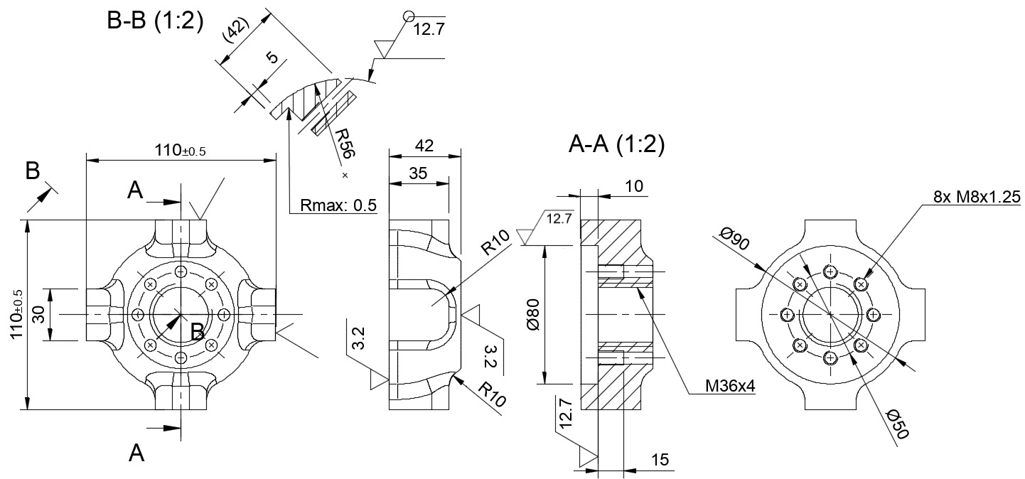
In this chapter, we will try to analyze a complex part, starting right from the 2D drawing. We will learn how to extract important pieces of information from drawing details and how to lay down a possible workflow with multiple placements using WCS offsets. After this analysis, we will learn how to create a multiple-setup CAM project with Fusion 360.

The goal of this book, and this chapter in particular, is to change your point of view and move you from a design perspective to a manufacturing perspective. We will work on a real-life scenario, where we will be...

Technical requirements

In order to follow along with this chapter, make sure that you have read Chapter 6 and Chapter 7.

Understanding the part

The first thing we need to do before creating a proper CAM setup is focus on the shape of our part. We want to aim to have a complete understanding of the part’s geometries, tolerances, and surface finish. Not concentrating on analyzing the part may lead to different machining approaches; that’s why it is so important to take our time and check the drawings with the highest attention.

In the next few pages, we will explain how to machine the following part on a three-axis machine. The following figure shows a 2D drawing of the part we will be looking at:

Figure 8.1: Part 2D drawing

Figure 8.1: Part 2D drawing

What data can we extrapolate from this drawing?

  • The component’s overall dimensions are 110 x 110 x 42 mm.
  • On the two planes defined by the 42 mm dimension, a good surface finish (3.2 microns) is required, so we should use a stock thicker than 42 mm and then machine it down to 42 mm with a finishing pass. For example...

Choosing part placements

When studying part placements, most of the time, we can follow different paths, but some of them may be more complex than others. I’m going to explain what I think is the best solution regarding our specific example, but it may not be the only solution according to the type of machine at our disposal and the holding fixture we intend to use.

So, now that we have seen the part we plan to create in Figure 8.1, we have to imagine how to move from a stock of 110 x 110 x 45 mm to the final shape. As we discovered from the drawing, we have to machine both sides of the stock as the features will appear on both sides.

Since most milling operations have to be performed on the rounded side, I would machine this side last:

Figure 8.2: Part placements

Figure 8.2: Part placements

As you can see in Figure 8.2, during the first placement (labeled as #1), I plan to perform the following operations:

  • Back side facing
  • Circular slot milling
  • Drilling...

Choosing a part fixture

How do you fix a stock to the machine working area? There is no all-encompassing rule, but we can say that we should always try to take advantage of the part's shape to lock it onto the working area.

Let’s review the part again to find some possible solutions:

Figure 8.3: 3D view of the part

Figure 8.3: 3D view of the part

At first glance, a simple and cheap solution would be to use a stock vise to hold it from the squared unmachined faces.

As shown in Figure 8.4, using a large set of vises to hold the stock is a good solution during the first placement since there is a large contact area between the faces:

Figure 8.4: Part fixture

Figure 8.4: Part fixture

During the second placement, however, the same vises not only provide a smaller contact area that may lead to vibrations but they may also collide with the cutting tool performing the exterior machining.

Since we said that a large number of parts have to be machined, we may have to...

Choosing WCS offsets

As we mentioned previously, machining the two placements together can improve productivity and reduce overall costs. This takes us to an important choice we must define before any further consideration: do we want to perform a single setup for both placements or do we want to set two distinct setups each with its own coordinate system?

There is a minor difference between the two, but it is incredibly important to understand. Let’s look at the following figure to help us:

Figure 8.6: Single versus multiple setups

Figure 8.6: Single versus multiple setups

On the left, we can find a CAM program with a Single Setup for both placements. This means that the two placements are considered by Fusion 360 as a single part to be machined with the same origin for the work coordinate system (WCS). It is the simplest approach, but it has the dangerous drawback of forcing us to precisely fix the two components at the exact location specified inside the G-code program; any minor...

Defining the first setup

The manufacturing environment for milling is very similar to the one we explored for turning, and we should already be familiar with most of the panels and commands:

Figure 8.7: The two parts to model

Figure 8.7: The two parts to model

As you can see, for better clarity, I decided to model two parts: the model on the left is a solid, showing how the part should look after the first placement has been completed, while the part on the right is the final result after the second placement has been fully worked.

Splitting the part into two distinct models – one for each placement – is not mandatory, but I think that considering the part as two distinct parts can be more intuitive for a beginner.

Now, let’s launch the Setup tab. We should be presented with three panels:

  • Setup
  • Stock
  • Post Process

Just like we have done in previous chapters, we will explore each panel one by one.

Setup tab

On the Setup tab, we can find...

Defining the second setup

In this section, we have to repeat more or less what we explored during the first setup. However, don’t worry – we will only review the important differences from what we’ve already reviewed.

Setup tab

First, let’s look at the Setup tab again:

Figure 8.11: The Setup tab

Figure 8.11: The Setup tab

As you can see, this time, I selected the final part to be machined, and I put the Origin parameter of the stock on the corner of the aluminum block.

This time, with the Fixture option, we can pick the template fixture that holds the stock in place. This way, our simulation will be able to check collisions between the tool and the holding fixture; this is not mandatory – if we did things properly, we shouldn’t expect this type of issue – but we can never tell!

Stock tab

On the Stock tab, we only need to check if the overall dimension of the block is correct:

Figure 8.12: The Stock tab

Figure 8.12:...

Summary

That concludes this chapter! It may have seemed quite complex due to the introduction and usage of WCS offsets, but it is way simpler than it sounds; we will clarify this process in the next few chapters. Also, despite being a book oriented to CAM novices, the part we are trying to machine is quite complex and up until now has offered several examples of analysis that will come in handy in our daily machining.

To recap what we learned, first, we discovered the part we have to machine with our CNC. Then, using the drawing, we analyzed the part to understand the best setup strategy. After that, we analyzed the needed placements to be able to machine the entire geometry and discovered the best solution to hold the part during the second placement. Finally, we created two setups that will be used in the following chapters for our milling operations.

In Chapter 9, we will learn how to implement several milling strategies, such as face milling, shoulder milling, drilling, and...

lock icon
The rest of the chapter is locked
You have been reading a chapter from
Making Your CAM Journey Easier with Fusion 360
Published in: Mar 2023Publisher: PacktISBN-13: 9781804612576
Register for a free Packt account to unlock a world of extra content!
A free Packt account unlocks extra newsletters, articles, discounted offers, and much more. Start advancing your knowledge today.
undefined
Unlock this book and the full library FREE for 7 days
Get unlimited access to 7000+ expert-authored eBooks and videos courses covering every tech area you can think of
Renews at $15.99/month. Cancel anytime

Author (1)

author image
Fabrizio Cimò

Fabrizio Cimò is an Italian engineer who has always had a passion for the world of 3D graphics and design. During his first degree in industrial design, he started uploading video lessons covering 3D modeling tools such as Rhinoceros, Blender, and Fusion 360 on his YouTube channel. Sometime later, Autodesk noticed his work and asked him to keep promoting Fusion 360 as an official student ambassador. During this time, he also joined Dynamis PRC, a racing team from Milano PT competing in the Formula SAE championship; thanks to this experience and his avid curiosity, he improved his knowledge of the manufacturing world. Today, Fabrizio works as a machine designer for an important company in the laser-cutting sector.
Read more about Fabrizio Cimò