Reader small image

You're reading from  3D Printing Blueprints

Product typeBook
Published inAug 2013
PublisherPackt
ISBN-139781849697088
Edition1st Edition
Tools
Concepts
Right arrow
Author (1)
Joe Larson
Joe Larson
author image
Joe Larson

Joe Larson, known online as "the 3D Printing Professor," is one part artist, one part mathematician, one part teacher, and one part technologist. It all started in his youth, doing BASIC programming and low-resolution digital art on a Commodore 64. As technology progressed, so did Joe's dabbling, eventually taking him to 3D modeling while in high school and college, and he momentarily pursued a degree in computer animation. He abandoned that and instead became a math teacher, and then moved to software development for 10 years before returning to education, teaching technology in college. When Joe first heard about 3D printing, it took root in his mind, and he went back to dust off his 3D modeling skills. In 2012, he won a Makerbot Replicator 3D printer in the Tinkercad/Makerbot Chess Challenge, with a chess set that assembles into a robot. Since then, his designs on Thingiverse have been featured on Thingiverse, Gizmodo, Shapeways, Makezine, and other places. He currently produces weekly videos about design for 3D printing on his YouTube channel, http://www.youtube.com/user/mrjoesays.
Read more about Joe Larson

Right arrow

Chapter 5. Modular Robot Toy

3D printers can make a number of useful and practical things. But what's the point if you can't have fun too? This blueprint is for a 3D printed poseable robot in multiple parts that connects together with 3D printed connectors. It will be connected with two types of connectors, a pin connector that will do the majority of the joints, and a ball and socket connector for the head.

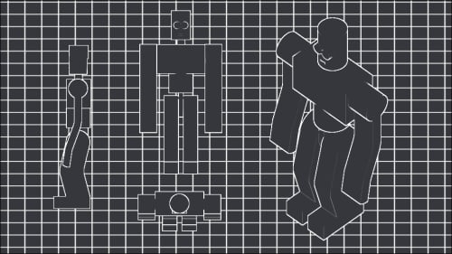
Before this project begins a lot of planning has to be done. Often projects list this start long before the modeling program opens up. This should be considered normal for any design project. Fortunately in this case the planning is already done and the modeling can begin.

The straight pin connector used here is loosely based on a connector created by Tony Buser on Thingiverse; modified to fit this project. This connector relies on the flexible nature of the plastic to get the head into a smaller hole, until it is past the opening, and can spring back to hold the part in place. When designing...

Making the connector


Start a new blender project, clear the workspace, and save the file. Create a new directory under the Makerbot Blueprints directory in Documents called Ch 5 Robot Toy. Enter the directory and save this file as Peg.blend.

Tip

Instead of designing everything in one file in this project, multiple files will be generated. This is a good way to keep parts organized, and keep the outliner from being overrun with objects. This is especially a good idea when the parts being designed might be reusable in future projects.

  1. Add (Shift + A) a Cylinder to the scene. Change the cylinder's Radius to 3.5 to bring it to a total diameter of 7mm.

  2. In the Properties pane under the Object tab change the name of the cylinder to PegBody.

  3. Rotate (R) the PegBody around the y axis (Y) 90 degrees.

    Tip

    If the rotation is accomplished with the key sequence R, Y then type 90 and press Enter to end the rotation action, it doesn't matter what view it is done in, the result will always be the same.

  4. In the Front...

Constructing a robot


The peg is done and its hole is defined. Now, to build something that will use them. This new build will need the PegHole from the other project.

  1. Start a new project (Ctrl + N). Clear the scene and Save (Ctrl + S) this project in the same directory as Peg.blend but name it Robot1.blend.

  2. In the Info panel on the top of the screen select File | Append or press Shift + F1.

  3. Select the Peg.blend file. Select the Object directory and select the PegHole. The PegHole from the previous project will be brought into the Robot1 project.

The robot as planned will need four pegs. Two at the shoulders, one at the torso, and one at the hips. To make things easier the one at the hips will be this peg at origin so it doesn't have to move and the robot will be built around it. Rename this PegHole to PegHip.

Engineering the body

  1. Hide (H) the PegHip for now.

  2. Jump to the front (Numpad 1) orthographic (Numpad 5) view.

  3. Add (Shift + A) a cube.

  4. Scale (S) it 0.5. Scale (S) again and press Enter to end...

Assembling the parts to print


A gentle reminder to Save (Ctrl + S) and perform incremental saves is in order. Hopefully, frequently saving is a habit at this point.

Building the parts like this is good for getting proportions and alignment correct, but is not appropriate for printing. Each part will be prepared for printing individually using a new view mode called Local, accessed from the View | View Global/Local menu options at the bottom of the 3D View panel or by using the slash on the number pad (Numpad /).

  1. Select the head and Duplicate (Shift + D) it.

  2. Name the duplicate PrintHead.

  3. Enter local view (Numpad /).

    The only object visible will be the PrintHead that was the last object selected. This is different than hiding all other objects. This can be confusing since any attempts to modify other objects won't work as expected until local view is exited. Always look for the label (Local) on the view description in the upper-left of the 3D View panel.

  4. Apply all the modifiers to the PrintHead...

Printing and assembly


Print Head.STL, Body.STL, Torso.STL, Arms.STL, Legs.STL, and four copies of Peg.STL. Snap three of the pegs into the holes in the body. Snap the torso onto the peg at the bottom of the body. Push the last peg through the hole in the bottom of the torso.

Snap the legs into the hip peg on either side. Snap the arms. Press the head into the neck, join firmly being careful not to break the neck joint. If it does break remove it with a pair of needle nosed pliers and glue it back in place with superglue. Allow it to dry and then try again. Then pose and play with the new robot.

Extra credit


Making a robot toy was a huge undertaking. But now that it's done why not go off the pattern and make a new style that is compatible with the old? There's a reason this project was named Robot1.blend. Your own robot doesn't need to follow the strict alignment that this one did, that was just for tutorial purposes. Make a rounder robot based on a sphere or one that's all cubes. Make a robot with spikes and blades for hands. Just be sure to plan a flat surface for printing and remember the overhang.

If multiple robots are made to use the same sized connectors, then the parts can be mixed and matched between them. With only four different robots trading heads, bodies, arms, and legs there are a potential 256 different robot combinations that could come from them. That's a lot of play for a little bit of modeling.

Summary


In this chapter, we learned a new way of connecting printed objects with custom connectors. Peg and ball joints were taught and their utility was demonstrated. The tolerances, or how much space needs to be in-between printed parts, was also explored.

In the next chapter another way of making parts interact using gears will be explored.

lock icon
The rest of the chapter is locked
You have been reading a chapter from
3D Printing Blueprints
Published in: Aug 2013Publisher: PacktISBN-13: 9781849697088
Register for a free Packt account to unlock a world of extra content!
A free Packt account unlocks extra newsletters, articles, discounted offers, and much more. Start advancing your knowledge today.
undefined
Unlock this book and the full library FREE for 7 days
Get unlimited access to 7000+ expert-authored eBooks and videos courses covering every tech area you can think of
Renews at $15.99/month. Cancel anytime

Author (1)

author image
Joe Larson

Joe Larson, known online as "the 3D Printing Professor," is one part artist, one part mathematician, one part teacher, and one part technologist. It all started in his youth, doing BASIC programming and low-resolution digital art on a Commodore 64. As technology progressed, so did Joe's dabbling, eventually taking him to 3D modeling while in high school and college, and he momentarily pursued a degree in computer animation. He abandoned that and instead became a math teacher, and then moved to software development for 10 years before returning to education, teaching technology in college. When Joe first heard about 3D printing, it took root in his mind, and he went back to dust off his 3D modeling skills. In 2012, he won a Makerbot Replicator 3D printer in the Tinkercad/Makerbot Chess Challenge, with a chess set that assembles into a robot. Since then, his designs on Thingiverse have been featured on Thingiverse, Gizmodo, Shapeways, Makezine, and other places. He currently produces weekly videos about design for 3D printing on his YouTube channel, http://www.youtube.com/user/mrjoesays.
Read more about Joe Larson