Reader small image

You're reading from  3D Printing Blueprints

Product typeBook
Published inAug 2013
PublisherPackt
ISBN-139781849697088
Edition1st Edition
Tools
Concepts
Right arrow
Author (1)
Joe Larson
Joe Larson
author image
Joe Larson

Joe Larson, known online as "the 3D Printing Professor," is one part artist, one part mathematician, one part teacher, and one part technologist. It all started in his youth, doing BASIC programming and low-resolution digital art on a Commodore 64. As technology progressed, so did Joe's dabbling, eventually taking him to 3D modeling while in high school and college, and he momentarily pursued a degree in computer animation. He abandoned that and instead became a math teacher, and then moved to software development for 10 years before returning to education, teaching technology in college. When Joe first heard about 3D printing, it took root in his mind, and he went back to dust off his 3D modeling skills. In 2012, he won a Makerbot Replicator 3D printer in the Tinkercad/Makerbot Chess Challenge, with a chess set that assembles into a robot. Since then, his designs on Thingiverse have been featured on Thingiverse, Gizmodo, Shapeways, Makezine, and other places. He currently produces weekly videos about design for 3D printing on his YouTube channel, http://www.youtube.com/user/mrjoesays.
Read more about Joe Larson

Right arrow

Chapter 3. Face Illusion Vase

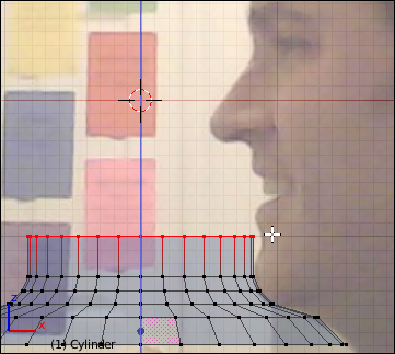
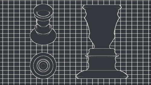
There is an old illusion where the silhouette of two faces are shown towards each other with their noses close together, but if you look at the space between the faces, the image shifts in your eyes and appears to be of a single ornate vase. With 3D printing, it is possible to make this illusion a reality. More than just a reality, it is possible to use a real face to make the illusion.

In the previous chapter, a number of topics including manipulating the view, and creating and manipulating objects were introduced. Also, the habit of making frequent saves and using incremental saves were taught, practiced, and enforced. In this chapter and in all the following chapters, saving will be left to you. It's generally a good idea to make an incremental save at every major section marked by a heading, and doing smaller saves as much as possible.

This chapter will focus on importing an image to help guide modeling, the tools that can be used to trace that image with...

Getting a profile


Before opening Blender, the first thing to do is get a side profile image of a face. With a camera you can take an image of yourself or someone you know. Alternately, searching online for side profile picture can turn up something usable. A good picture will be as side-on as possible and will have a clear outline of the face. Save the image to the local disk and make note of its location. If no other image can be found, the following image can be acquired at http://www.thingiverse.com/thing:90754. Locate the following image, right-click on it and choose Save Image As… (or Save As… depending on the browser) and save the image in a directory, where it can be found later:

Now, just like last time, open up Blender and clear the scene. Start a new project, Select All objects (A) and Delete (X). In the menu bar, navigate to File | Save As... and navigate to the MakerbotBlueprints directory we created in the first project, then create a new directory for this project and in that...

Tracing the silhouette


In Blender, an object can be just a single-shaped line that can later be turned into a 3D object. Blender doesn't have a single-line object, so instead the simple objects if possible will be added and a single line will be extracted from it. Perform the following steps to trace the silhouette:

  1. Add (Shift + A) an object.

  2. Under the Mesh menu, click on Plane:

  3. Begin the Rotation (R) operation.

  4. Press X to lock the rotation around the x axis.

  5. Type 90 to rotate exactly 90 degrees.

  6. Press Enter or left-click to end the rotation operation.

  7. In the Object tab (the one that looks like an orange cube) on the left-side bar, name this object Face Line.

Unlike before, when we added a cube that only looked like a square because of our viewing angle, a plane really is just a square and has no depth. A plane isn't enough to define a printable shape but it can be used as a starting point for making a printable shape with depth.

Note

All 3D shapes are comprised of some basic building block. Vertices...

Creating a vase from the lines


It may not be immediately evident from its name, but the Screw modifier is the tool that will be used to turn this line into a 3-dimensional shape:

  1. Switch to the Modifier tab (the one with the blue wrench) in the right-side bar.

  2. Click on the Add Modifier button.

  3. Click on the Screw modifier in the second column:

  4. Uncheck Smooth Shading.

  5. Change the Render Steps field to 32.

  6. Change the Steps field to 32:

Like many modifiers in Blender, Screw can be used for many more things than making vases, and experimentation outside of this exercise is encouraged.

Why 32 steps? Those who are new to 3D modeling or computer science may wonder why such a seemingly arbitrary number like 32 is used. There are two reasons for choosing 32.

The first reason is because 32 is divisible by 4, so that the vertices line up with the four axes directions nicely. If 30 were used, there would be vertices that lined up nicely with the horizontal axis, but on the vertical axis there would be points straddling...

Using Solidify to make walls


The vase looks good from this angle, but if the view is rotated it becomes apparent that this it is just the shell of a vase. If this were to be printed as it is, nothing might get printed. The shape needs to be solidified into a shape, and fortunately there's a modifier for that. Solidify can be applied to this shell to make a printable object.

Just a quick reminder that constantly saving (Ctrl + A) and incremental saves (F2, +) is always a good idea.

Before using Solidify in the Modifier tab (blue wrench), press the Apply button to finalize the Screw modifier. Then add and adjust the settings of the Solidify modifier as follows:

  1. Press the Add Modifier button.

  2. Select the Solidify modifier in the second column from the pop-up menu:

  3. Change the Thickness field to 2 for a 2 mm wall:

There is something very wrong. The Solidify modifier seems to work properly for the bottom half of the vase, but not for the top. The reason for this is another very important concept in 3D...

Making a solid base


Before continuing, now is a good time for another gentle reminder about saves. Use saves (Ctrl + S) and incremental saves (F2, +) from time to time.

A proper vase will hold water, so this vase will have to be modified so the base instead of having a 2 mm wall will be solid, and the bottom of the body and foot closed so it can hold water and print. This involves selecting the internal walls of the vase, which can be difficult to do without selecting the external walls as well, so a new selection operation will the used; Select More:

  1. Apply the Solidify modifier.

  2. Toggle to the Wireframe view on (Z).

  3. Enter the Edit Mode (Tab).

  4. (De)select All (A).

  5. In the front view, zoom in on the base and identify a line of vertices, where the noses meet which are on the inside and carefully Border Select (B) the whole line. Try to identify a line that is not so close to external lines in this view to make the selection easy:

  6. From the menu at the bottom of the View Panel, click on Select More or...

Printing the vase


The vase is now complete and can be exported. Exit the Edit Mode and with the final vase selected navigate to File | Export | Stl (.stl) in the menu bar. Then process in the usual way for printing. The example model had some overhang in the mouth area but printed okay:

Extra credit


There are often many techniques that can be employed to make the same thing. In fact, there is another way that this sort of vase could have been created using mostly just the techniques learned in the previous chapter. Starting with a cylinder at the bottom of the reference image, extrude the top slightly, and scale each extruded segment:

The disadvantage of this method is that it is difficult to get the same level of detail, and the wall inside the body may not be exactly 2 mm the whole way. It is left to the modeler to verify tolerances. The advantage of this method is that a clever modeler could take a picture of two different people facing each other and make a vase that looks different on each side. It requires some clever manipulation of the reference image to line up the features and could make an excellent gift.

Summary


Creating this vase taught many important 3D modeling skills and principles as follows:

  • Importing a reference image

  • The Screw modifier

  • The Solidify modifier

  • Normals, viewing, and fixing

  • Deleting vertices

  • Creating new faces from selections

The next chapter is another cool project that involves making something to match the dimensions of a real-life object, a useful, if somewhat silly, ring that can hold an SD card on a finger.

lock icon
The rest of the chapter is locked
You have been reading a chapter from
3D Printing Blueprints
Published in: Aug 2013Publisher: PacktISBN-13: 9781849697088
Register for a free Packt account to unlock a world of extra content!
A free Packt account unlocks extra newsletters, articles, discounted offers, and much more. Start advancing your knowledge today.
undefined
Unlock this book and the full library FREE for 7 days
Get unlimited access to 7000+ expert-authored eBooks and videos courses covering every tech area you can think of
Renews at $15.99/month. Cancel anytime

Author (1)

author image
Joe Larson

Joe Larson, known online as "the 3D Printing Professor," is one part artist, one part mathematician, one part teacher, and one part technologist. It all started in his youth, doing BASIC programming and low-resolution digital art on a Commodore 64. As technology progressed, so did Joe's dabbling, eventually taking him to 3D modeling while in high school and college, and he momentarily pursued a degree in computer animation. He abandoned that and instead became a math teacher, and then moved to software development for 10 years before returning to education, teaching technology in college. When Joe first heard about 3D printing, it took root in his mind, and he went back to dust off his 3D modeling skills. In 2012, he won a Makerbot Replicator 3D printer in the Tinkercad/Makerbot Chess Challenge, with a chess set that assembles into a robot. Since then, his designs on Thingiverse have been featured on Thingiverse, Gizmodo, Shapeways, Makezine, and other places. He currently produces weekly videos about design for 3D printing on his YouTube channel, http://www.youtube.com/user/mrjoesays.
Read more about Joe Larson