Reader small image

You're reading from  3D Printing Blueprints

Product typeBook
Published inAug 2013
PublisherPackt
ISBN-139781849697088
Edition1st Edition
Tools
Concepts
Right arrow
Author (1)
Joe Larson
Joe Larson
author image
Joe Larson

Joe Larson, known online as "the 3D Printing Professor," is one part artist, one part mathematician, one part teacher, and one part technologist. It all started in his youth, doing BASIC programming and low-resolution digital art on a Commodore 64. As technology progressed, so did Joe's dabbling, eventually taking him to 3D modeling while in high school and college, and he momentarily pursued a degree in computer animation. He abandoned that and instead became a math teacher, and then moved to software development for 10 years before returning to education, teaching technology in college. When Joe first heard about 3D printing, it took root in his mind, and he went back to dust off his 3D modeling skills. In 2012, he won a Makerbot Replicator 3D printer in the Tinkercad/Makerbot Chess Challenge, with a chess set that assembles into a robot. Since then, his designs on Thingiverse have been featured on Thingiverse, Gizmodo, Shapeways, Makezine, and other places. He currently produces weekly videos about design for 3D printing on his YouTube channel, http://www.youtube.com/user/mrjoesays.
Read more about Joe Larson

Right arrow

Chapter 4. SD Card Holder Ring

Some 3D printers can print directly from an SD card instead of being hooked up to a computer all the time. But what if the computer used to prepare files is not close to the 3D printer? Some sort of SD card holder can be used in order to keep the card safe, but not to tie your hands up (in case you don't have any pockets available). A ring that you can put an SD card in is just the thing.
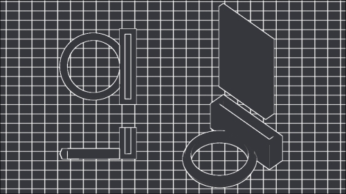
In this chapter an object will be modeled to real-life specifications. The challenges of matching real-life measurements with plastic shrinkage will be explored as well. In the end, a functional real-life useful object will be created, even though some would claim Blender isn't suited for CAD-like precision work.

As precise placement of new objects is important in this project, remember that if the 3D cursor is ever moved with an accidental left-mouse click, navigate to View | Align View | Center Cursor and View All or press Shift + C to put the 3D cursor back at the origin...

Taking measurements


This would be a very simple build using the tools taught in previous chapters. So this set of instructions will focus on using a different paradigm of designing. In this build, the Apply button in the modifiers will not be used so that the object remains modifiable until the end. This technique works well for simple shapes but can be a problem when the geometry of the model becomes increasingly complex.

Before opening Blender, some measurements must be gathered. Careful measurements need to be taken of the finger that the ring will be on and of the SD card. A digital caliper is an excellent tool to take measurements with:

My middle finger measures 19.3mm at the widest point. If a digital caliper is not available, another way to measure a finger is to wrap a piece of paper around the finger, mark where it overlaps, and use a ruler to find your finger's circumference. Then consult the next chart to find out the standard ring size and diameter:

Modeling the finger


Now that all the measurements have been taken, it is time to go to Blender. Start a new scene; (De)select All (A) objects and Delete (X) them. Then save the scene (Ctrl + S) in a new directory under the Makerbot Blueprints directory called Ch4 SD Card Ring and name the project file as SD Card Ring.

  1. Add (Shift + A) a cylinder. In the side bar to the left, change the options for the cylinder. Change the value of Vertices to 64 so the cylinder is smoother than default. Change the value of Radius to half the diameter of the measured finger. Change the value of Depth to 10:

    Note

    Blender can take simple equations in these boxes, so instead of dividing the diameter in half to get the radius, simply type the diameter followed by /2 and it will divide it by 2 for you. So, in the preceding example, typing 19.3/2 resulted in the value of Radius being shown.

  2. Select the Object tab (orange cube) from the properties on the side bar to the right, rename this cylinder to Finger as this cylinder...

Putting the ring on the floor


The goal of this section will be to place the important objects so they sit on the XY plane without going below it.

  1. With only the ring object selected, begin the Grab/Move (G) operation.

  2. Press the Z key to lock the ring's movement along the z axis.

  3. Type 2 to move the ring up half its depth.

  4. Press Enter to end the grab operation.

    Tip

    Like scaling, you can lock movement to a single axis. This works regardless of the view and ensures that the movement is predictable.

This puts the Finger cylinder in an odd place, but as it is still both above and below the ring cylinder, it is not important and can just be left where it is.

Making a test ring


  1. Similar to what has been done in other projects, add a Boolean modifier to the ring and difference the Finger object from it. The Finger object obscures the effect of this operation, so hide it. One way to do this is to select (right-click) the Finger object and navigate to Show/Hide | Hide Selected from the menu at the bottom of the 3D View Panel Object or press the H key. Another way is to click on the icon that looks like an eye in the Outliner on the line for the Finger object:

  2. The ring is now perfectly serviceable, but there's no harm in making it a little more appealing. Enter the Edit Mode (Tab). Again, notice that without applying the modifier, its effects are undone while in Edit mode. Loop Cut (Ctrl + R) the cylinder around the middle-click and left-click twice when selecting, so the slice does not slide up or down:

  3. Scale (S) the newly sliced ring slightly outwards. The scaled ring of points should not extend more than 1 mm (one small grid square in the background...

Resizing the test ring


Now we are back to Blender to make a new test ring. This time, instead of starting from scratch, reload the project and resize the existing ring. Care has to be taken when resizing the ring to insure that it doesn't extend below the XY plane.

  1. Unhide the Finger cylinder by clicking on the eye icon in the Outliner on the line for the Finger object.

  2. Select All (A) objects.

  3. Begin the Scale (S) operation.

  4. Press Shift + Z to lock the scale operation to all but the z axis.

  5. Type 1.03 to scale the selected object just slightly larger.

  6. Press Enter to end the scale operation.

    Tip

    Pressing Shift and X, Y, or Z key when in an operation such as scale or grab, locks the operation to everything but the selected axis, regardless of view. With rotation, however, the effects are less predictable.

    Note

    The logic behind using 1.03 as a scaling factor is that past experimentation has proven this to be the right amount to overcome ABS shrinkage. It also coincidently brings the new ring very close...

Adding an SD card holder


  1. (De)select All objects (A) and press Shift + H. Remember that Shift + H hides all but the selected object; however, as no objects are selected, all objects will be hidden to clear the way for what is to come. Add (Shift + A) a cube to the scene.

    It is interesting to note that the default cube created by blender is not a unit, that is to say, its sides are not all 1 mm. They are in fact 2 mm each. This makes the default cube less desirable for precise scaling. Fortunately, it is an easy thing to make this cube a unit cube; however, first its dimensions can be used to move it on to the XY plane easily. Only this time a trick will be employed to control how the cube scales in the future. Instead of moving the whole cube up, the individual points will be moved up in the Edit Mode so that the object's origin is left where it is.

    Note

    Object origin was a problem in the last project causing the object's axes to be skewed in relation to the world orientation. In that project...

Adding the SD holder to the ring


Unhide the ring by clicking its eye icon in the Outline panel. Select SD Holder and Grab/Move (G) it in the x axis (X) until it is at the front of the ring. Depending on the view when the last operation was done, a problem may have been observed:

What happened to the hole for the SD card? Because the Boolean modifier was not applied, the hole stayed right where it was where the hidden SD Card object resides:

As amusing as this can be, this is an undesired behavior. There are two options. Either the Boolean operation can be applied before moving, or both objects can be moved together. As the stated goal of this project was to not use the Apply button, the choice is clear. Undo (Ctrl + Z) the move operators until the hole is where it belongs, in SD Holder. Then unhide the SD Card object by clicking on its eye icon in the Outliner view. Select both SD Holder and SD Card by right-clicking on one, then holding Shift and right-clicking on the other. Then Grab/Move...

Extra credit


Leaving modifiers unapplied becomes undesirable when the object's geometry gets too complex. Simply performing Boolean operations on cubes together may not cause a crash, but adding Boolean operations to multiresolutioned objects and moving them around or changing the order of their modifiers has been known to slow down or even crash even the heartiest of systems.

Try to see how quickly Blender will slow down by making several cubes, adding multiresolution modifiers to increase their polygon count and Boolean them together all without pressing the Apply button. Add more and more multiresolution cubes and move them around to see when performance becomes choppy. It may be surprising how little time it takes.

With the measurements of an SD card available, any object can be turned into an SD card holder. Why not make an SD holder key chain or an SD holder that clips to a breast pocket? Add an SD holder to a mini mug or vase to turn decorative items into something functional. Measure...

Summary


Leaving modifiers in place is a technique that allows for a high degree of flexibility that is particularly desirable for something that stands a good chance of being customized. If someone else wanted their own SD card holder ring, it would be trivial to resize the ring and adjust to position of the SD Holder.

Also in this chapter, Blender's tools for precise placement were employed to make an object match real-life measurements. Blender may never be able to compete with other CAD programs for precision, nevertheless with some careful planning and clever manipulation, Blender is capable of extremely precise modeling.

The next chapter is a huge challenge where the tools and techniques learned so far will be applied to making a modular multi-part toy with moving parts. The modeling will be simple, but the result will be impressive as the ways that parts can be joined together and designing those joints to be printable will be explored.

lock icon
The rest of the chapter is locked
You have been reading a chapter from
3D Printing Blueprints
Published in: Aug 2013Publisher: PacktISBN-13: 9781849697088
Register for a free Packt account to unlock a world of extra content!
A free Packt account unlocks extra newsletters, articles, discounted offers, and much more. Start advancing your knowledge today.
undefined
Unlock this book and the full library FREE for 7 days
Get unlimited access to 7000+ expert-authored eBooks and videos courses covering every tech area you can think of
Renews at $15.99/month. Cancel anytime

Author (1)

author image
Joe Larson

Joe Larson, known online as "the 3D Printing Professor," is one part artist, one part mathematician, one part teacher, and one part technologist. It all started in his youth, doing BASIC programming and low-resolution digital art on a Commodore 64. As technology progressed, so did Joe's dabbling, eventually taking him to 3D modeling while in high school and college, and he momentarily pursued a degree in computer animation. He abandoned that and instead became a math teacher, and then moved to software development for 10 years before returning to education, teaching technology in college. When Joe first heard about 3D printing, it took root in his mind, and he went back to dust off his 3D modeling skills. In 2012, he won a Makerbot Replicator 3D printer in the Tinkercad/Makerbot Chess Challenge, with a chess set that assembles into a robot. Since then, his designs on Thingiverse have been featured on Thingiverse, Gizmodo, Shapeways, Makezine, and other places. He currently produces weekly videos about design for 3D printing on his YouTube channel, http://www.youtube.com/user/mrjoesays.
Read more about Joe Larson

Circumference (mm)

Circumference...