


Writing the first lines of code – Hello World
The first code that is introduced in programming is called Hello World. In microcontrollers, the first code blinks an LED. This is usually an onboard LED if one is present.
You will need your MKR board, a micro-USB cable, and the Arduino IDE to get started.
Installing the board
Use the following steps to set up your board:
- Launch the Arduino IDE, if it’s not running.
- Connect one end of the micro-USB cable to your computer.
- Remove the Arduino MKR board from its packaging and any black foam that it’s sitting on. Failure to do so will result in some unexpected behavior.
- Connect the MKR board to the other end of the micro-USB cable.
- A green power LED should light up to show that the board is now powered on.
- Select Arduino MKR WiFi 1010 from the board selector dropdown at the top of the IDE. If the board isn’t listed, go to Board Manager on the left, search for
SAMD, and click Install under Arduino SAMD Boards.
We are now ready to program the MKR board. The IDE should look similar to the following figure.
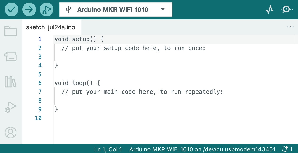
Figure 1.5 – The IDE in the ready state
Blinking the onboard LED
The MKR board has an onboard RGB LED. RGB stands for Red, Green, and Blue. The RGB LED is connected to three pins, as follows:
- Green: pin 25
- Red: pin 26
- Blue: pin 27
The three pins let you control the three colors independently, control the intensity, and mix the colors to produce other colors.
Let’s write code to blink one or more of the LEDs. To do this, we will count from 0 to 7 in binary. This will give us three digits ranging from 000 to 111. If the digit is 0, we will turn off the corresponding LED, and if it’s 1, we will turn it on. We can do this using the pins in digital mode, which will not control the intensity of the light.
The code that does this follows. You can find this code in the GitHub repository for this book, or you can type it out:
#include <WiFiNINA.h>
#include <utility/wifi_drv.h>
#define redLED 25
#define greenLED 26
#define blueLED 27
byte counter = 0;
void setup() {
  WiFiDrv::pinMode(redLED, OUTPUT);
  WiFiDrv::pinMode(greenLED, OUTPUT);
  WiFiDrv::pinMode(blueLED, OUTPUT);
}
void loop() {
  WiFiDrv::digitalWrite(blueLED, bitRead(counter, 0));
  WiFiDrv::digitalWrite(greenLED, bitRead(counter, 1));
  WiFiDrv::digitalWrite(redLED, bitRead(counter, 2));
  counter > 6 ? counter = 0 : counter++;
  delay(1000);
}
The explanation for the code is as follows:
- The first two lines include the libraries that are necessary for us to address the onboard LEDs. The LEDs on the MKR WiFi 1010 must be addressed via the
WiFilibrary. - The next three lines define three constants that reflect the pins we would like to address. This isn’t mandatory, but it makes it easier for us to know what pins we are addressing in our code.
- The next line defines a variable called
counter, which defaults to0. - Within the
setup()function, we set all three LEDs to output mode. - Within the
loop()function, we do three things:- The first three lines set the state of each of the LEDs by using the
digitalWrite()function that is found within theWiFiDrvlibrary. This function takes two parameters: the pin and the state. The pin is specified using one of the constants we declared earlier, and the state is obtained by using thebitRead()function. This function, in turn, takes two parameters: the number we would like to read and the index of the least significant bit we would like to read. For example,bitRead(6, 1)would first convert the decimal number6into the binary number110, then it would read the second rightmost digit (it uses a0-based index). The result would be1. - The next line increases our counter using a ternary operator. It is basically an
if-elsestatement that sets the counter to0if the value is greater than6or increases it if it isn’t. - The final line introduces a delay of a second (1,000 milliseconds) so that the human eye can see the LED that is lit.
- The first three lines set the state of each of the LEDs by using the
Give the code a try and see how it runs on the board. The lights should range from off to blue and through a range all the way to white. There is a total of seven colors represented in this loop.
You will find the light to be too bright unless it is behind something such as a handkerchief that serves to dull the brightness. You can fix this by using analogWrite() and setting the value to 64 for a quarter of the brightness.
There is a second advantage to using analogWrite(). You can mix different ratios of the three primary colors to arrive at a lot more colors.