


Learning about the Arduino programming language
The Arduino programming language is a subset of the C/C++ programming language. It’s okay if you haven’t written C/C++ before now, as getting started with Arduino is pretty straightforward.
Getting started with Arduino
The quickest way to get started is to click on the File menu on the Arduino IDE, then choose New. Doing that will give you a new file with a structure similar to the one in the following code block, which does nothing but give you a template to add instructions in:
void setup() {
}
void loop() {
}
The preceding code is made up of two sections:
- The first section,
void setup() {}, holds code that will be run exactly once when the microcontroller boots up. The code that gets executed is contained within the opening and closing curly brackets. Here is the code again:void setup() {}
- The next section of code,
void loop() {}, holds code that is executed repeatedly as long as the microcontroller is powered up. The code is also contained within the curly brackets. Here is the code again:void loop() {}
Let’s proceed to discuss GPIO pins.
General purpose input and output
A lot of the interaction that happens on a microcontroller is through the general purpose input and output (GPIO) pins. There are two categories of pins: digital and analog. The following pinout diagram for the MKR WiFi 1010 shows the pins.
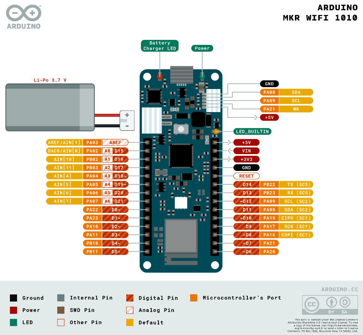
Figure 1.4 – Arduino MKR WiFi 1010 pinout diagram (source – https://docs.arduino.cc/static/9d6534bb9783a42e3527a8c03472ad10/ABX00023-full-pinout.pdf)
The pin labels are color-coded to make it easier to identify pins by their function. Some pins have only one use, such as the Power and Ground pins. Other pins have multiple uses. Pay attention to the labels that are closer to the board on the left and right. You will see that 22 pins can be used as digital pins, while 7 of those can be used as analog pins in addition. However, no pins are labeled as input or output.
Let’s discuss how to configure pins for input or output depending on whether the pin is digital or analog.
Digital pins
Digital pins represent a state that depends on the amount of electricity flowing through them. There are two states:
- Low state: This represents an
OFFstate or aFALSEstate. This is set when the amount of electricity is below a certain reference. - High state: This represents an
ONstate or aTRUEstate. This is set when the amount of electricity is above a certain reference.
A digital pin is configured as either of the following:
- An input pin, used for reading the state of a peripheral attached to it. An example of this is a button. You can read the state of an input pin using the
digitalRead()function. - An output pin, used to control the state of a peripheral attached to it. An example of this is an LED. You can set the state of an output pin using the
digitalWrite()function.
You can configure a digital pin using the pinMode() function. The first parameter is the pin number, and the second is one of INPUT, OUTPUT, or INPUT_PULLUP. You will see this used in the Hello World example very soon.
Analog pins
Analog pins can hold a state between 0 and 1023, which is proportional to the voltage passing through the pin. There are two possible directions:
- Input pins: These are connected to peripherals that send a voltage value over a range. This is how peripherals such as sensors work. You can read the value of the pin using the
analogRead()function. - Output pins: These are connected to peripherals that can operate over a variable range, such as electric motors and actuators. You can set the value of the pin using the
analogWrite()function.
You are now ready to write your first Arduino program.