

In this paragraph, we will modify the previous project and we will see how to control peripherals connected to Android Things. In more details, we will control the RGB led color using the three buttons. Each button controls a color (Red, Green, and Blue), so that when you press one button, Android Things turns on and off the corresponding color on the RGB led. To create this project, you need:
- Wire jumpings
- Resistors (200Ohm, 10Kohm)
- Three buttons
The following image shows the button that we will use in the project:
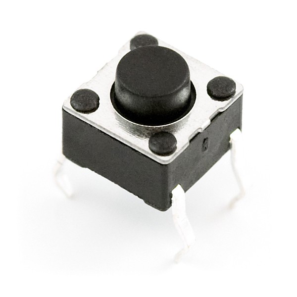
Source: https://www.sparkfun.com/products/97
The following image shows a 1 RGB Led:
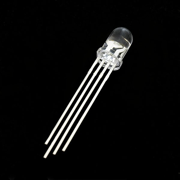
Source: https://www.sparkfun.com/products/10820
Note
Before connecting the devices and resistor to the board be sure that the board is disconnected from the PC, otherwise you could damage it.
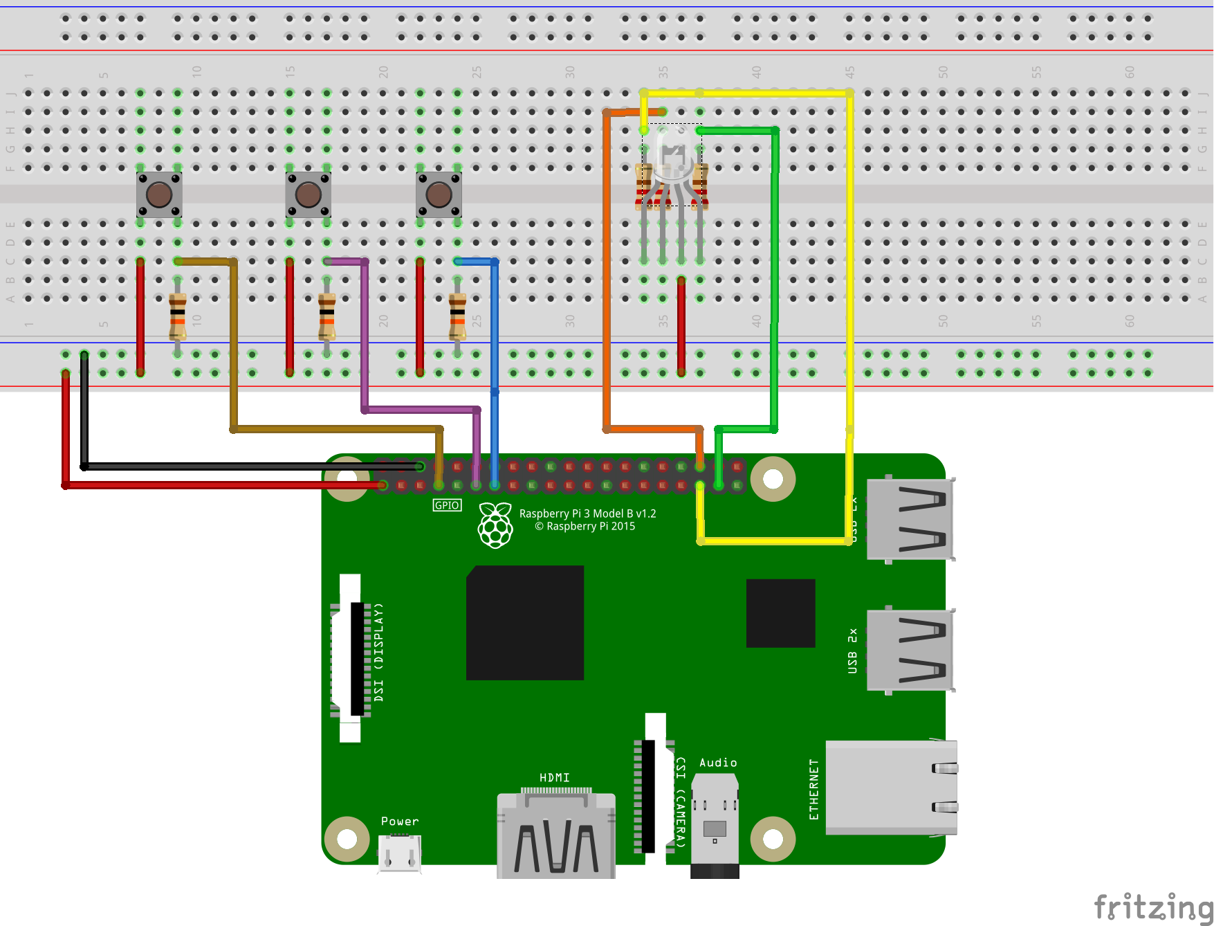
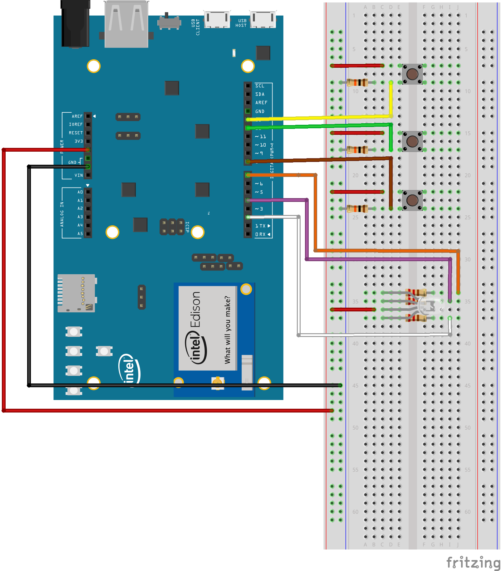
The following figure describes how to connect these components to the Raspberry Pi 3:
If you are using Intel Edison the schema is as follows:
The following image shows how to connect buttons in practice:
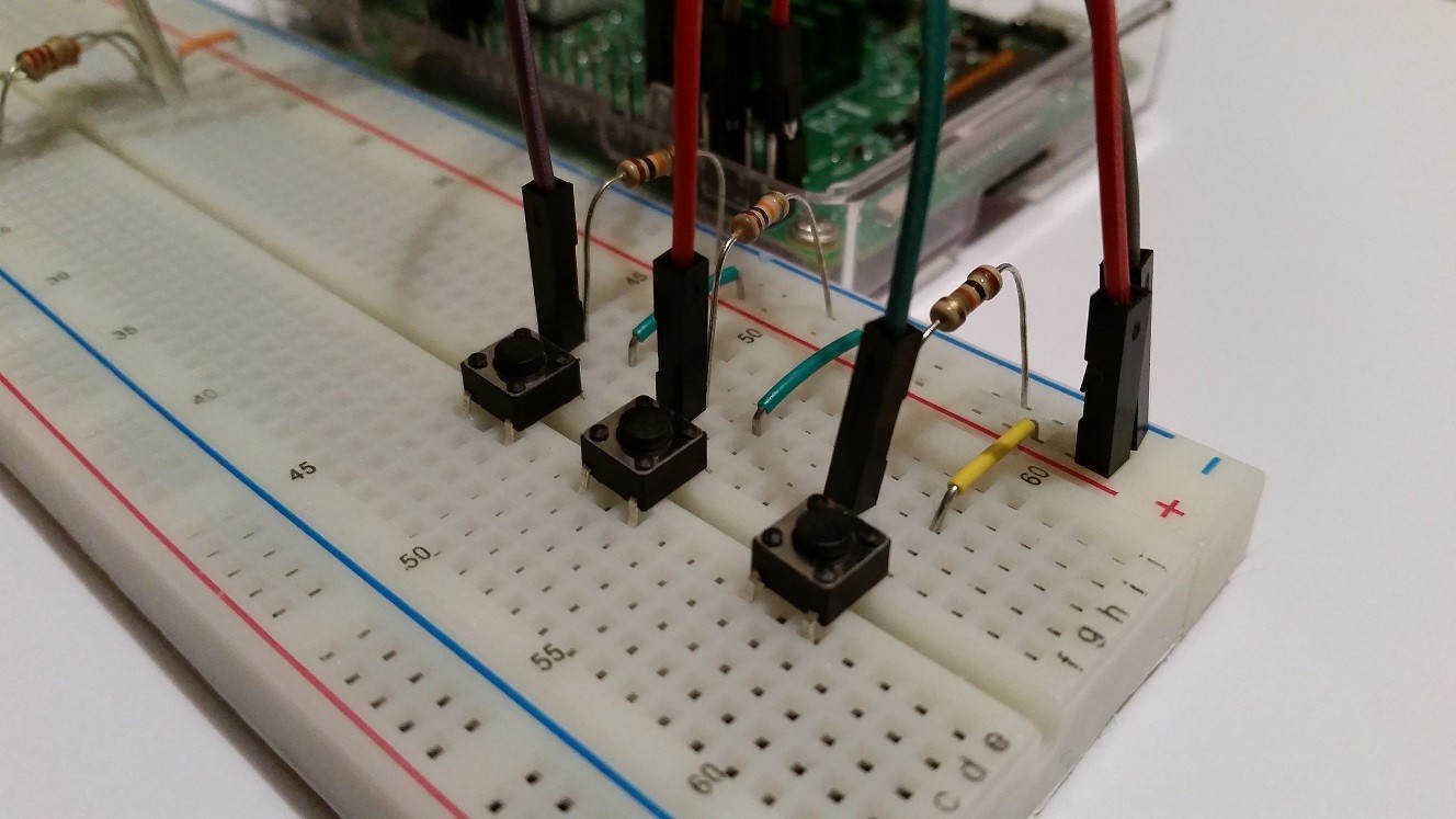
The connections are quite simple; a pull-down resistor of 10 Kohm connects one button pin to the ground. Each button has a pull-down resistor. Moreover, the following image shows how to connect the led:
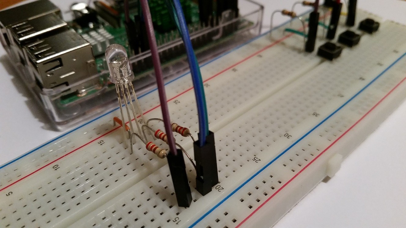
A 200 Ohm resistor connects each RGB led pin and the boards pin limiting the current flowing into the LED. The other pin, the anode pin, is connected to 3.3V for Raspberry Pi and +5V for Intel Edison. Before modifying the source code, it is necessary to add a library that helps us to interact with buttons easily. Open build.gradle (app-level) and modify the file adding the following lines:
dependencies {
...
compile 'com.google.android.things.contrib:driver-button:0.1'
}
Using this library, we can handle the button status. Moreover, we can create listeners to listen to button state changes.
Now open the MainActivity.java that you created in the project and add the following lines:
- In the
onCreatemethod add the following:
PeripheralManagerService manager = new PeripheralManagerService();This one of the most important classes introduced by Android Things SDK. By now, you should know that this class is used to interact with external peripherals. It exposes a set of methods to interact with several devices using different protocols (that is, GPIO, PWM, and so on). Using this class, an Android Things app turns on or off each board pin, so that it can control the external devices, or it can open a port for a specific purpose.
- Create three different instances of the
Buttonclass corresponding to each button used in the circuit:
Button button1 = new Button("IO13", Button.LogicState.PRESSED_WHEN_LOW);Note
One important thing to notice is that we have to specify the pin where the button is connected to the board. In the following code line, the pin is IO13.
By now, it is enough to know that each pin on the board has a specific name and these names change depending on the board. For example, if you use Intel Edison, the pin names are different from Raspberry Pi 3 pin layout. We will cover this aspect in the next chapter. The other parameter represents the button logic level when it is pressed. If you are using Raspberry Pi 3, then instead of the code line shown previously, you have to use the following:
Button button1 = new Button("BCM4", Button.LogicState.PRESSED_WHEN_LOW);Maybe you are wondering if there are some compatibility problems when we install an Android Things app on different boards. The answer is yes, but we will see in the next chapter how to handle this problem and how to create an app that is board-independent:
- Now add a listener to be notified when the user presses the button. We do it as if this is an Android app with a UI:
button1.setOnButtonEventListener(
  new Button.OnButtonEventListener() {
    @Override
    public void onButtonEvent(Button button, boolean
    pressed) { if (pressed) {
      redPressed = !redPressed;
      try {
        redIO.setValue(redPressed);
        }
        catch (IOException e1) {}
    }
  }
});
The interesting part is that we set the redIO pin value to 1 (high) or 0 (low) according to the button status. The redIO represents the pin that connects the red pin of the led. We get the reference to it using the following:
redIO = manager.openGpio("IO2");Do not worry now about this piece of code; we will cover it in the next chapter. Using the preceding code line, we open the communication to the LED using another board pin. The previous example is for Intel Edison, and again if you are using Raspberry, the pin name changes.
- Now repeat the same piece of code shown previously for the green and blue buttons:
button2.setOnButtonEventListener(new Button.OnButtonEventListener()
{
    @Override
    public void onButtonEvent(Button button,
    boolean pressed) {
        if (pressed) {
         greenPressed = !greenPressed; try {
             greenIO.setValue(greenPressed);
            }
        catch (IOException e1) {}
       }
     }
});- Where
greenIOis defined as follows:
greenIO = manager.openGpio("IO4");- While for the blue buttons:
button3.setOnButtonEventListener(new Button.OnButtonEventListener()
{
    @Override
    public void onButtonEvent(Button button,
    boolean pressed) {
        if (pressed) {
            bluePressed = !bluePressed; try {
                blueIO.setValue(bluePressed);
                }
            catch (IOException e1) {}
        }
    }
});- And the
blueIOis defined as follows:
blueIO = manager.openGpio("IO7");- Finally, we have to modify
Manifest.xml. From the Android point of view, an app uses theManifest.xmlto define the Android components such as Activity, Services, and so on.
This is still valid in the Android Things project, but there is a difference in the way it declares an Activity:
- Open the
Manifest.xmland look for the Activity definition. - Remove all the intent-filter tag.
- Add the following lines at the same position:
<intent-filter>
<action
android:name="android.intent.action.MAIN" />
<category android:name=
"android.intent.category.IOT_LAUNCHER" />
<category android:name=
"android.intent.category.DEFAULT" />
</intent-filter>
- Save the file.
The interesting part to notice is a new category type. If we want to execute an Activity that runs on an embedded device such as Raspberry or Intel Edison we have to add the category IOT_LAUNCHER.
That's all. Now you can connect the board to your PC/Mac. Press the run button at the top of Android Studio:
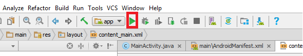
And wait until the board appears in the list of available devices, as shown in the following screenshot:
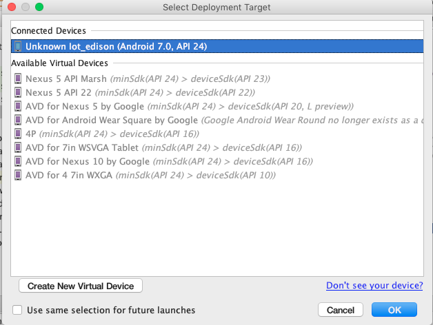
Now you can execute the app. The installation process is the same as used for the Android app. When the process completes you can start using the app.
When you press each button, you should see the led changing color, moreover, you can completely turn off the led.