

Exploring the in-vehicle network
The plethora of ECUs, sensors, and actuators gave rise to a diverse set of in-vehicle networking technologies. A common goal of these technologies is the need for reliable communication with deterministic behavior under harsh environmental conditions within low-cost constraints. The bulk of the ECUs rely on signal-based communication through automotive bus systems such as Controller Area Network (CAN/CAN-FD), FlexRay, Ethernet, and Local Interconnect Network (LIN). The increased demand for network bandwidth is constantly driving the in-vehicle networks to transition to higher bandwidth solutions such as Ethernet and GMSL.
While securing in-vehicle networks shares common challenges with general network security, the real-time performance constraints and limited payload sizes present unique challenges for many of the automotive networking protocols. In the following section, we will survey the most common automotive networking technologies and touch upon their unique security challenges. Understanding the primary features and common use cases of these protocols will serve as a basis for analyzing the security of the in-vehicle networking protocols in the following chapters.
CAN
It is hard to work on vehicle security without learning about how CAN works and the various security problems it suffers from. CAN is a serial communications protocol that is perfect for real-time applications that require dependable communication under harsh environmental conditions. It has been and remains a popular communication protocol due to its low cost and excellent reliability. CAN is used in a variety of vehicles, including commercial trucks, cars, agricultural vehicles, boats, and even aircraft:
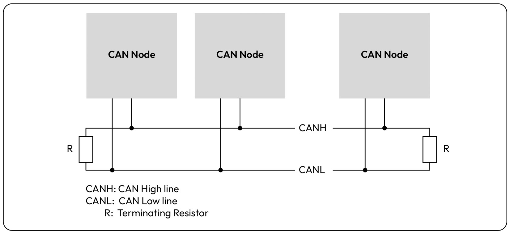
Figure 1.10 – Typical bus layout with multiple CAN nodes sharing a single CAN channel
The CAN physical layer supports bitwise bus arbitration, which ensures that the CAN node transmitting with the lowest CAN ID wins the arbitration, causing the other nodes to wait until the bus is idle before re-attempting transmission. This arbitration scheme can be potentially harmful if CAN nodes misbehave by attempting to acquire bus access greedily.
Another important feature of CAN is its built-in error handling strategy, which ensures that nodes experiencing transmit errors enter a bus-off state to stop disturbing other nodes. This minimizes bus disturbance and allows for application layer strategies to retry transmission after a back-off period. These rules are upheld if the CAN controller is conforming, as is the case with standard CAN-based devices. Note that in later chapters, we will examine the threat of non-conforming CAN controllers, which are intentionally designed to violate the physical and data link layer protocols. In those cases, the malicious CAN node can inject bit flips, creating continuous availability issues with the physical CAN channel.
When it comes to the flavors of CAN, there are three versions: CAN 2.0, CAN-FD, and the latest, CAN XL. CAN 2.0 is the most used since it’s the legacy protocol but its maximum payload size of eight bytes and a typical baud rate of 500 kbps makes it unsuitable for more bandwidth-hungry applications. As a result, CAN-FD was added, offering a larger payload of up to 64 bytes and a faster payload data rate, which is typically 2 Mbps. The final variant of CAN is CAN XL, which offers a maximum payload size of 2,048 bytes and up to 20 Mbps. Note that while each CAN protocol advertises a higher theoretical baud rate limit, factors such as bus length, bus load, signal quality, and EM interference force a lower typical baud rate to ensure the reliability of communication.
The CAN FD message’s frame format is shown in the following figure to help you visualize what a CAN frame looks like:
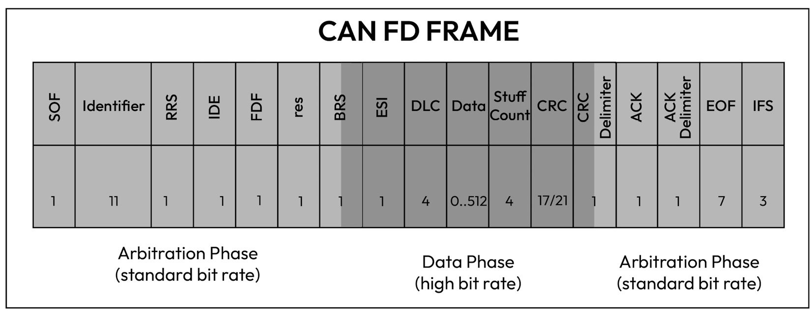
Figure 1.11 – CAN FD bit frame layout
CAN node receivers use the CAN identifier to determine how to interpret the payload content, also known as the PDU. The CAN ID is important for setting up acceptance filters so that a receiver can determine which messages it wants to receive or ignore. In addition to the CAN ID, the transmitter specifies the DLC field, which indicates the payload size, and the data field, which contains the actual payload. Note that the CRC field is automatically calculated by the CAN controller to ensure the receiver detects flips in the CAN frame occurring at the physical layer. Above the CAN data link layer, several CAN-based protocols exist, such as the transport protocol, diagnostic protocol, network management, and OEM-defined PDU Com layers. Diagnostics are particularly interesting for security as they allow an external entity with access to the onboard diagnostics (OBD) interface to send potentially harmful diagnostic commands. In later chapters, we will take an in-depth look at how the OBD protocol can be abused to tamper with emissions-related diagnostic tests, as well as OEM-specific diagnostic services. Another important use case of CAN is the transmission and reception of safety-critical PDUs that include sensor data, vehicle status messages, and actuation commands.
Discussion point 8
Given the small payload size of CAN 2.0 messages, and the low tolerance for message latency, can you think of a suitable way to protect the message integrity from malicious tampering?
FlexRay
A big driver for the automotive industry to transition to FlexRay was the desire for a more deterministic communication protocol that could offer guaranteed bandwidth to safety-critical messages. Unlike CAN, which allows the transmitter with the lowest CAN ID to always win the arbitration, FlexRay allocates time slots based on a Time Division Multiple Access (TDMA) structure:
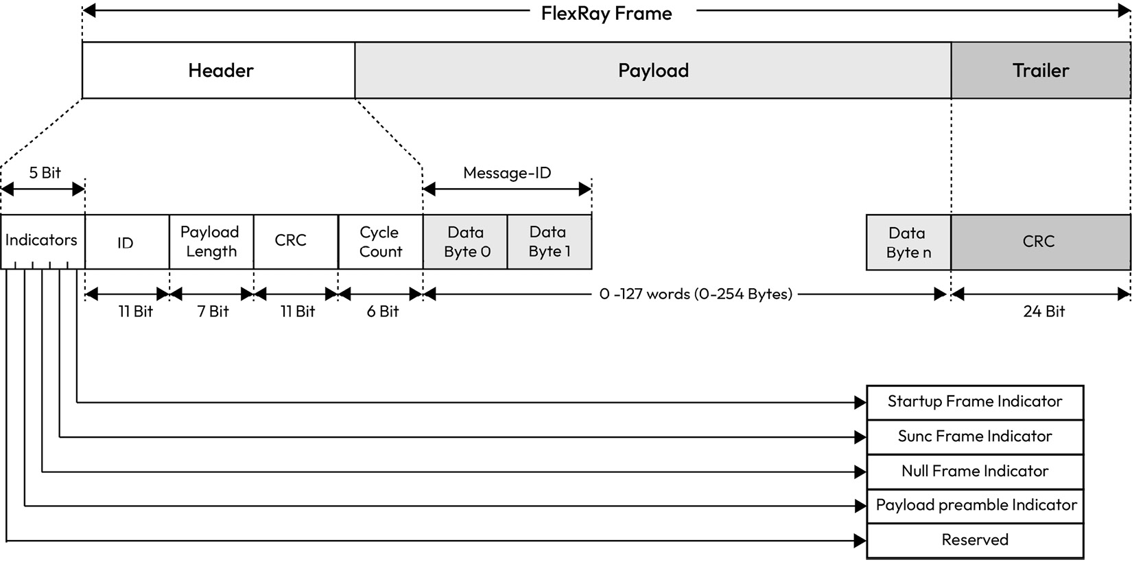
Figure 1.12 – FlexRay frame layout
Another benefit of FlexRay over CAN and CAN FD is the maximum payload of 254 bytes. Moreover, FlexRay offers a redundant configuration for the communication channel to reduce the possibility of failure with a data rate of up to 10 Mbps per communication channel. Where redundant communication is not critical, the redundant channel can be leveraged to boost the data rate to 20 Mbps. FlexRay features a static slot and a dynamic slot to allow fixed messages in reserved time slots to be transmitted, as well as dynamic messages that can be transmitted non-cyclically. The payload length has the same value for all messages transmitted in the static slot. On the other hand, the dynamic slot can have payload lengths of varying sizes.
Discussion point 9
Could the dynamic slot be abused by a malicious FlexRay node?
The payload preamble indicator field indicates whether a frame is a dynamic or static FlexRay message. In a dynamic message, the first two bytes of the payload are the message identifier, which allows for precise identification of the payload and finer control of acceptance filtering. The NULL frame indicator is used to send a message with a payload of zeroes to indicate that the transmitter was not ready to provide data within its allocated time slot. The CRC field is automatically calculated by the FlexRay controller to ensure channel errors are detected by the receiver. Critical to the correct operation of the FlexRay protocol is the use of time synchronization. Without this, senders will start transmission in the wrong time slots and the protocol will lose its reliability. In a FlexRay cluster, at least two FlexRay nodes must act as the synchronization nodes by transmitting a synchronization message in a defined static slot of each cycle. All FlexRay nodes can then compute their offset correction values using the fault-tolerant midpoint (FTM) algorithm. The FTM algorithm is used to ensure that the nodes in the FlexRay network are synchronized to exchange data in a coordinated and reliable manner. The FTM algorithm works by using a central node, known as the FTM, which acts as a reference point for the other nodes in the FlexRay network. The FTM node sends periodic synchronization messages to the other nodes in the network, which, in turn, use these messages to adjust their internal clocks to match the clock of the FTM node.
Discuss point 10
Can you think of a unique attack method that the FlexRay cluster is exposed to? Could the FTM algorithm be abused by a malicious node to cause a loss of network synchronization?
LIN
A LIN bus is a single-master, multiple-satellite networking architecture based on the universal asynchronous receiver-transmitter (UART) protocol and is typically used for applications where low cost is more critical than data transmission rates. In a LIN network, the master sends a command containing a synchronization field and an ID, while the satellite responds with a message payload and checksum. Like CAN 2.0, the payload size is up to 8 bytes but at a much lower bit rate, typically 19.2 kbps:
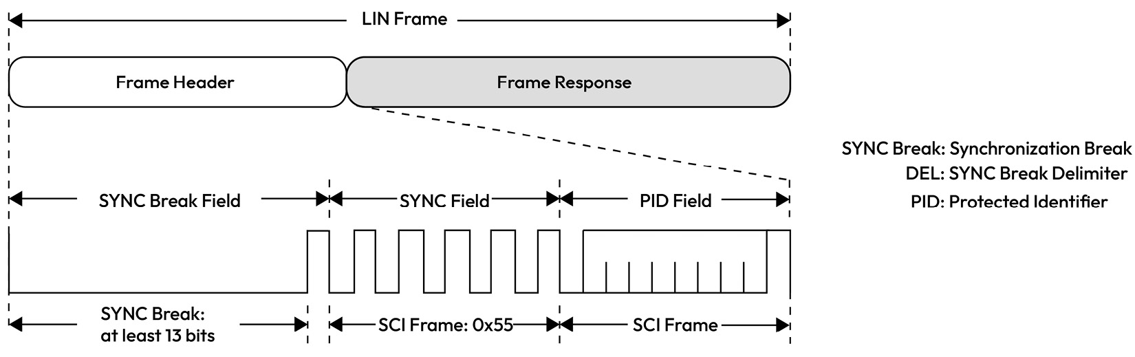
Figure 1.13 – LIN frame structure
LIN communication is based on a schedule table maintained by the LIN master, who uses it to issue LIN header commands directed at specific LIN satellites. LIN is perfect for sensor and actuator networking applications such as seat control, window lifters, side-view mirror heating, and more. A typical vehicle network will contain a CAN node that is also a LIN master acting as a gateway between the CAN network and the LIN sub-network. This enables such a master to control the LIN satellites by sending them actuation commands and diagnostic requests. Therefore, the LIN master node is a critical link in exposing deeply embedded sensors and actuators in the rest of the vehicle through a CAN-LIN gateway node.
Discussion point 11
Can you think of a way the LIN bus can become exposed to security threats?
UART
The UART communication protocol supports the asynchronous transmission of bits and relies on the receiver to perform bit sampling without the use of a synchronized clock signal. The transmitting UART node augments the data packet being sent with a start and stop bit in place of a clock signal. The standard baud rate, which can go up to 115,200 bps, is 9,600 bps, which is adequate for low-speed communication tasks:
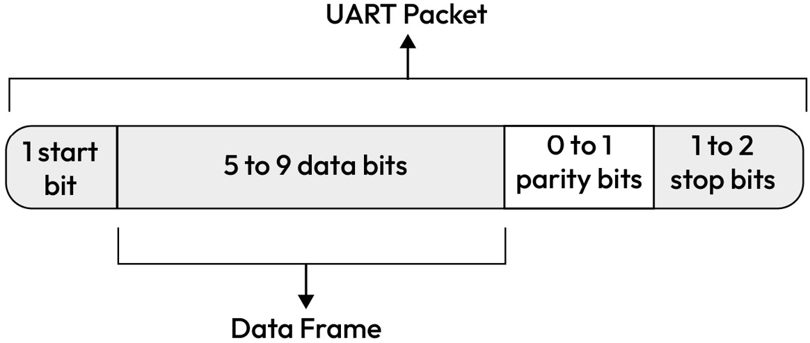
Figure 1.14 – A UART packet showing start, stop, data, and parity bits
UART is typically used in automotive applications to open debug shells with an MCU or SoC, which naturally makes it an interesting protocol for attackers to abuse.
SENT
The Single Edge Nibble Transmission (SENT) bus, known as SAE J2716, provides an accurate and economical means of transmitting data from sensors that measure temperature, flow, pressure, and position to ECUs. The SENT bus is unique in that it can simultaneously transfer data at two different data rates of up to 30 kbps, outperforming the LIN bus. The primary data is normally transmitted in the fast channel, with the option to simultaneously send secondary data in the slow channel.
A typical SENT frame consists of 32 bits, as shown in Figure 1.15, and breaks up the data into 4-bit nibbles that are terminated by a CRC to ensure frame integrity against corruption errors:
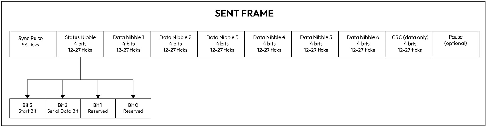
Figure 1.15 – SENT frame format
Although SENT is robust, easy to integrate, and has high accuracy, the SENT messages can still be affected by noise, timing problems, and subtle differences in implementations, which limits its use to specific sensor types.
GMSL
Gigabit Multimedia Serial Link (GMSL) is a high-speed multigigabit serial interface used originally in automotive video applications such as infotainment and advanced driver assistance systems (ADASs). It allows for the transmission of high-definition video and audio signals between components within the vehicle, such as cameras, displays, and audio processors. It uses a serializer on the transmitter side to convert data into a serial stream, and a deserializer on the receiving side to convert the serial data back into parallel words for processing. GMSL can transfer video at a speed of up to 6 Gbps:
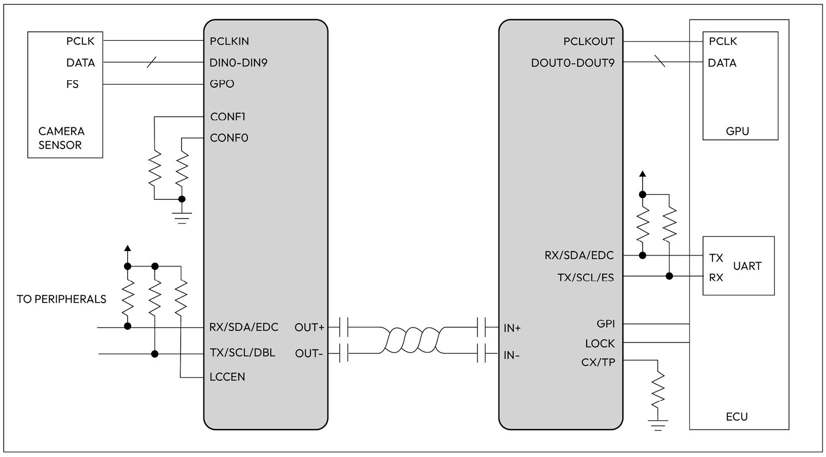
Figure 1.16 – GMSL use case diagram based on analog devices (ADI) GMSL deserializer
Figure 1.16 shows a typical configuration of a camera application where a serializer chip (shown on the left) is connected to a camera sensor, while a deserializer chip (shown on the right) is connected to the ECU. In addition to its use in audio and video transmission, GMSL technology is used in automotive applications to transmit other types of data, such as high speed sensor data and control signals.
I2C
Inter-Integrated Circuit (I2C) is a two-wire serial communication protocol mainly used for communication between an MCU or SoC and a peripheral such as a camera sensor or a memory chip (EEPROM) that is positioned near the controlling unit. I2C supports data rates of up to 5 Mbps in ultra-fast mode and as low as 100 kbps in standard mode. I2C comes with an address frame that contains the binary address of the satellite device, one or more data frames of 1 byte in size that contain the data being transmitted, start and stop conditions, read/write bits, and ACK/NACK bits between each data frame:
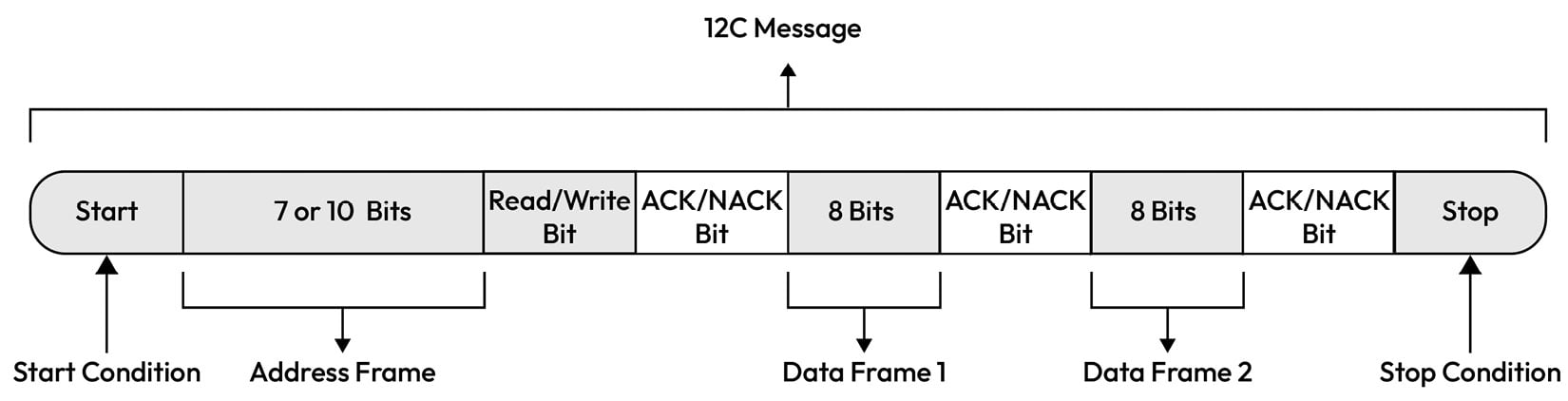
Figure 1.17 – I2C message layout
Ethernet
The constant growth of bandwidth demands due to content-rich use cases has led the automotive industry to gradually adopt Ethernet through a set of IEEE standards known as Automotive Ethernet [9]:
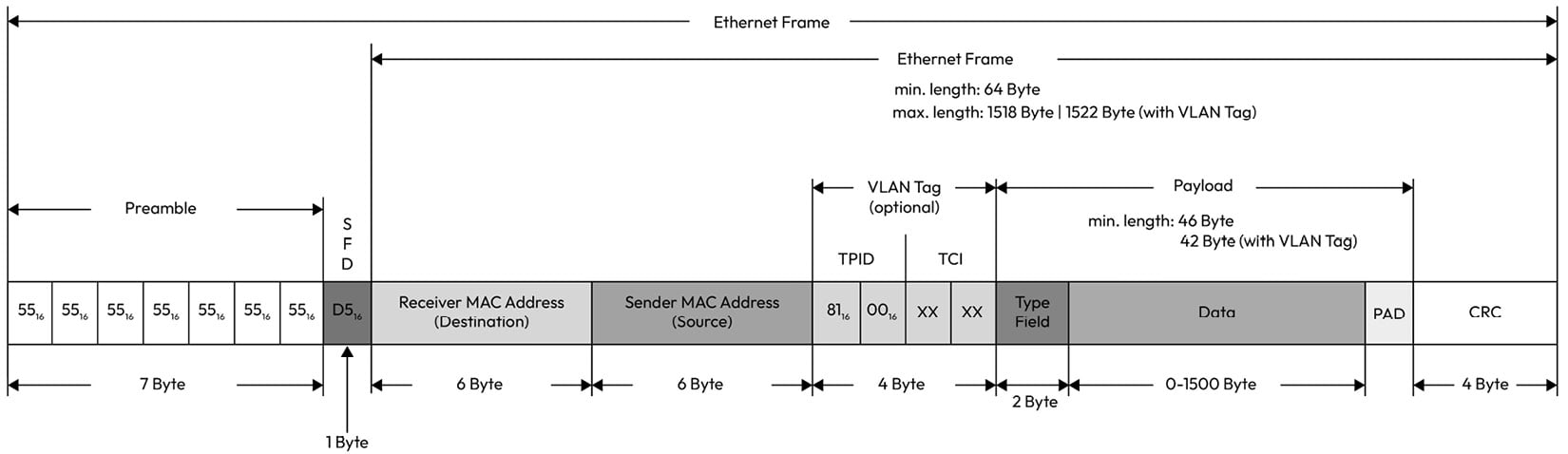
Figure 1.18 – Ethernet frame layout
Ethernet-based communication offers high bandwidth with great flexibility for integration with standard products outside the automotive domain. Automotive Ethernet covers a data rate range starting from 10 Mbit/sec standardized through 10Base-T1S up to 10 Gb/sec standardized through 10Gbase-T1. This makes it suitable for a range of automotive use cases, from time-sensitive communication to high-throughput video applications.
One of the primary differences between Ethernet and automotive Ethernet is the physical layer, which is designed to handle stringent automotive EMC requirements. Another difference is the introduction of the IEEE time-sensitive networking (TSN) standard, which offers preemption to allow critical data to preempt non-critical data, time-aware shaping to ensure a deterministic latency in receiving critical data, precise timing (PTP) to synchronize clocks within the network, per-stream filtering to eliminate unexpected frames, frame replication, and elimination, as well as an audio-video transport protocol for infotainment-related use cases.
J1939
SAE J1939, defined by the Society of Automotive Engineers (SAE), is a set of standards that defines how ECUs communicate via the CAN bus in heavy-duty vehicles:
|
Layer |
Name |
Standard |
|
7 |
Application |
SAE J1939-71 (applications) SAE J1939-73 (diagnostics) |
|
6-4 |
Presentation, Session, and Transport |
Not used but included in the Data Link layer |
|
3 |
Network |
J1939-31 |
|
2 |
Data Link |
J1939-21 |
|
1 |
Physical |
J1939-11 |
For communication among ECUs within the truck network, the standard ISO 11898 CAN physical layer is used. However, for communication between the truck and the trailer, a different physical and data link layer based on ISO11992-1 is used.
At the data link layer, J1939 supports peer-to-peer messages in which the source and the destination address are provided in the 29-bit CAN ID. It also supports broadcast messages, which contain only the source address. This allows multiple nodes to receive the message. A unique feature of J1939 over traditional CAN is the Parameter Group Number (PGN) and Suspect Parameter Number (SPN). Unlike passenger vehicles that rely heavily on OEM-defined PDUs, J1939 comes with a set of standard PGNs and SPNs, which makes it easier for people observing the J1939 CAN bus to decode the meaning of the messages.
Let’s look at an example PGN and its corresponding SPNs, as defined in the SAE J1939 standard.
The PGN 65262 is reserved for engine temperature and given a fixed transmission rate of 1s, a PDU length of 8 bytes, and a default priority of 6. The 8 bytes are distributed as follows:
|
Start Position |
Length |
Parameter Name |
SPN |
|
1 |
1 byte |
Engine Coolant Temperature |
110 |
|
2 |
1 byte |
Engine Fuel Temperature 1 |
174 |
|
3-4 |
2 bytes |
Engine Oil Temperature 1 |
175 |
|
5-6 |
2 bytes |
Engine Turbocharger Oil Temperature |
176 |
|
7 |
1 byte |
Engine Intercooler Temperature |
52 |
|
8 |
1 byte |
Engine Intercooler Thermostat Opening |
1134 |
The SPN is the equivalent of a signal ID that’s commonly used in signal-based communication for passenger vehicles. J1939 standardizes the SPN name, description, data length, and even the resolution to ensure the raw-to-physical interpretation is performed correctly.
When transferring data that is larger than 8 bytes, you will need to use the transport protocol, which in J1939 supports message transfers of up to 1,785 data bytes. This is done through two modes: connection mode data transfer, in which ready-to-send (RTS) and clear-to-send (CTS) frames are used to allow the receiver to control the data flow, and a broadcast announce message (BAM), which allows the sender to transmit messages without the data flow control handshake.
Discussion point 12
Can you think of ways the handshake messages can be abused by a malicious network participant?
The transport protocol supports diagnostic applications, which rely on a set of parameter groups (PGs) reserved for handling different diagnostic services. PGs designated as diagnostic message (DM) types fulfill the UDS protocol, which is commonly used for passenger vehicle diagnostics. When observing a diagnostic frame over J1939, you can easily look up the diagnostic trouble code by observing the SPN field (which contains the unique identifier of a fault parameter) and the FMI field (which contains the type of failure detected).
Finally, source address management and mapping to an actual function are handled by the network management layer. Unlike passenger vehicle network management protocols, which are designed to support ECU sleep and wakeup, J1939 uses network management to define how ECUs get admitted to the network and how device addresses are administered in dynamic networks. A simple form of J1939 network management is the transmission of the Address Claimed parameter group (PGN 0x00EE00) of every ECU after booting and before the start of communication. With Address Claim, the device name and a predefined device address are exchanged to describe the network topology. For a detailed understanding of the address claiming protocol, we encourage you to read J1939-31 (see [ 1] in the Further reading section). For now, let’s be aware that this ability to claim certain addresses can present security challenges if a network participant is not behaving honestly.
So far in this chapter, we’ve surveyed the most common in-vehicle networks. We intentionally left out external network types such as Wi-Fi, Bluetooth, 5G cellular, GNSS, and RF communication. We will explore threats that emanate from these communication domains in the following chapters. Now that we have learned how to interconnect components through the vehicle network, let’s explore some special vehicle components that allow an ECU to sense and react to changes in the vehicle’s environment.