


Electronic control units
ECUs are at the heart of the E/E architecture and consist primarily of the processing elements and electronic components necessary to perform one or more vehicle functions, such as steering, information display, seat control, and more. In the simplified view of Figure 1.1, we can see seven ECUs interconnected through the vehicle network (for demonstration purposes only). One such ECU is the electronic braking control module (EBCM), which is responsible for active safety functions such as anti-lock braking systems (ABSs) and electronic stability control (ESC). Another ECU is the battery management system (BMS), which is commonly found in electric vehicles.
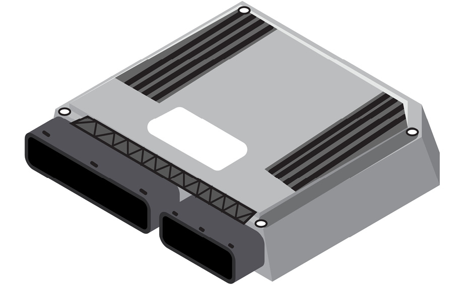
Figure 1.2 – Closed box view of an ECU
The electronic components of the ECU are housed in a sealed enclosure that is designed to withstand harsh environmental conditions such as heat, vibration, and electromagnetic interference. The black connector shown in Figure 1.2 enables the ECU to interface with the rest of the vehicle E/E architecture through a set of cables known as the wire harness. Mapping the pin out of the connector is the first step to determine which signals are relevant for cybersecurity. The power inputs, physical network bus lines, hard-wired sensor inputs, and actuation outputs are among the typical assets that are considered for protection against security threats.
If you were to crack open the ECU enclosure, as shown in Figure 1.3, you would find a PCB populated with various passive and active electronic components, such as relays, solenoids, resistors, capacitors, diodes, the power management integrated circuit (PMIC), network transceiver memory chips, and, most importantly, a microcontroller (MCU) or system on chip (SoC).
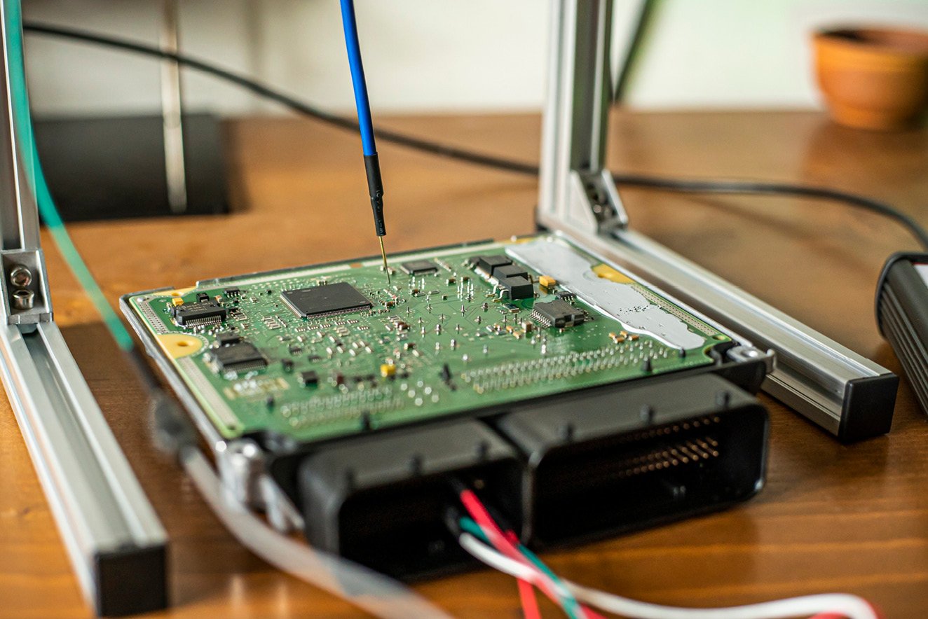
Figure 1.3 – Open box view of an ECU
Due to their power, cost, and timing performance constraints, most ECU types are driven by an MCU that realizes the vehicle functions through software running on one or more CPU cores embedded within the MCU.
SoCs, on the other hand, integrate several components into one chip to offer higher computation resources with larger memory and networking capabilities, making them well suited for applications such as infotainment and autonomous driving systems.
Discussion point 1
Can you think of any assets that are worth protecting once the PCB layout is exposed?
Answers to all discussion points are provided at the end of this chapter.
To answer the preceding question, let’s first dive a bit deeper into the hardware architecture of MCU-based ECUs before moving on to SoCs.
Looking at MCU-based ECUs
An MCU-based ECU executes software through one or more symmetric CPU cores that fetch code and data from the MCU’s internal flash memory. Code execution from the internal flash is a key requirement to meet the hard real-time constraints of these ECUs. Even when external flash memory is used, it is normally restricted to storing data such as images or audio files, as is the case with an instrument cluster ECU.
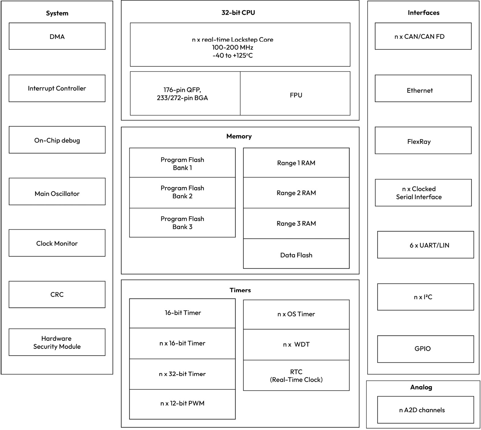
Figure 1.4 – A typical MCU block diagram
MCUs come in many variants, each tailored for a specific vehicle ECU application type. For example, an MCU for engine control will have many high-precision timer units, while an MCU for body control will have a large number of general-purpose input/output (I/O) pins. When analyzing the cybersecurity threats of a specific ECU, it is important to understand the different peripherals that are available as they may introduce a unique set of assets and attack surfaces. Figure 1.4 shows a block diagram for a typical 32 bit microcontroller with multiple peripherals and networking interfaces.
Looking back at Figure 1.3, we can start to explore the assets that can be probed for by an attacker who has possession of the ECU. For one, the MCU’s memory contents are an interesting target for exposure. This is where the ECU control software and calibration data are stored and therefore are of value at least to the ECU supplier, who may wish to protect their intellectual property against illegal access. Together with the vehicle’s original equipment manufacturer (OEM), they both want to prevent probers from discovering exploits that can be leveraged in more sophisticated attacks. However, since the memory is embedded inside the MCU, by having possession of the open ECU, an attacker cannot directly probe the memory contents. Instead, they will have to explore ways to leverage the on-chip debug features or serial flash programming interfaces to gain access to the memory’s contents.
Discussion point 2
Looking at the block diagram in Figure 1.4, can you guess what might be another asset that is of interest to an attacker who has possession of our ECU?
Looking at SoC-based ECUs
At first glance, the main difference between the SoC and MCU is the increased level of complexity and the diverse set of peripherals offered. For one, the SoC has a combination of CPU clusters that serve different use cases. The application CPUs feature multiple symmetric cores that target computationally intensive functions such as perception, path planning, and sensor fusion. On the other hand, the real-time CPUs feature multiple symmetric cores that target safety-critical functions such as fault monitoring and error reporting. In addition to the common network peripheral types of an MCU, we expect to see a higher number of network interfaces with higher bandwidth (for example, Ethernet 1 GB/10 GB links and PCIE). One significant difference with the MCU-based architecture is that code execution is out of DRAM as opposed to the embedded flash. Additionally, eMMC and QSPI flash interfaces are commonly used to support loading code and data from external storage devices. As is the case with the MCUs, SoCs come in different variants as they aim to serve specific vehicle use cases. For example, you will find that SoCs for ADAS applications are equipped with computer vision and deep learning accelerators, while SoCs for infotainment are equipped with video encoders/decoders for media streaming:
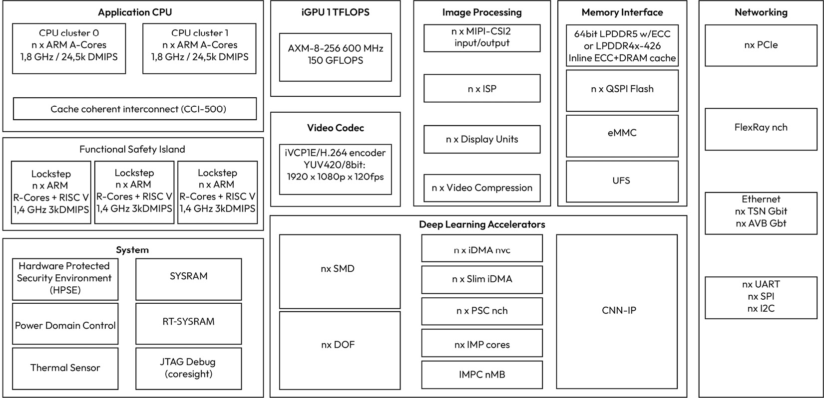
Figure 1.5 – Typical block diagram of an automotive SoC
In addition to storing typical software and calibration data, an SoC has additional unique objects of value, such as machine learning models that are programmed in storage, as well as stored camera images, videos, and vehicle logs that may contain users’ private data. Machine learning models are valuable intellectual property to the ECU supplier and the OEM that helped create them. On the other hand, camera images and video data are important to vehicle owners who care about protecting their privacy. Vehicle logs serve many purposes and can be especially useful in accident investigations. Furthermore, since memory is exposed on the PCB, an attacker can attempt to directly dump the contents of the eMMC or probe the QSPI lines to extract memory contents.
Discussion point 3
Looking at the block diagram in Figure 1.5, can you spot other assets that are interesting to an attacker who has possession of an SoC-based ECU?
Continuing with our “peeling the onion” exercise, let’s look at the MCU and SoC software layers.
Looking inside the MCU and SoC software layers
The most differentiating feature of MCU-based automotive ECUs is their hard real-time performance requirements and their high degree of determinism, both of which are critical to controlling time-sensitive operations such as braking, deploying airbags, steering, and engine combustion. As a result, an MCU periodic software task may only deviate within milliseconds, and sometimes even microseconds, from its nominal execution rate before the application starts violating its safety and reliability objectives.
Before AUTomotive Open System ARchitecture (AUTOSAR) was founded, if you wished to examine the software architecture of an ECU, you would have to work in a software team at the OEM or for an automotive supplier. But thanks to the AUTOSAR consortium’s efforts of creating a standardized basic software architecture and standard application interface layer, security professionals can gain insights into a typical ECU software architecture simply by learning the basics of the AUTOSAR software architecture.
Note
AUTOSAR is a worldwide development partnership of vehicle manufacturers, suppliers, service providers, and companies from the automotive electronics, semiconductor, and software industries.
Let’s start by looking at the MCU-based software architecture based on the AUTOSAR classic variant:
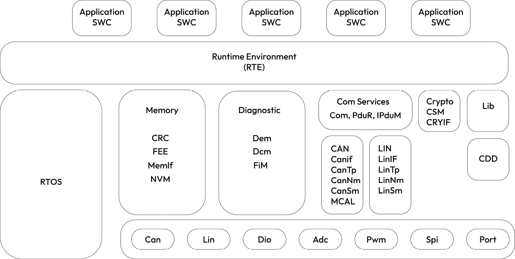
Figure 1.6 – Simplified AUTOSAR classic software block diagram
At the heart of the AUTOSAR classic software architecture is the AUTOSAR real-time operating system. The AUTOSAR operating system offers several memory, timing, and hardware resource isolation and protection guarantees to support safety-critical applications. As we will see in the following chapters, some of these safety features are also useful for hardening AUTOSAR-based applications against cyber threats.
Another signature feature of AUTOSAR classic is the hardware abstraction layer, which exposes the MCU features through well-defined interfaces to ensure software portability across different hardware platforms. Configuring the microcontroller abstraction layer (MCAL) correctly and with security in mind is a critical part of reducing the attack surface against the rest of the AUTOSAR layers.
Besides the MCAL, several AUTOSAR software layers are critical for security. For example, if the Com services layer is improperly configured, it can be abused by a software application to send spoofed messages to other ECUs on the shared CAN network. Similarly, the memory stack can be exploited to tamper with the non-volatile memory contents. The diagnostic layer can cause fake diagnostic data to be erased or inserted, or even worse, critical diagnostic services to be unlocked under unsafe conditions. Even without a deep knowledge of the AUTOSAR Crypto services layer, we can guess that cryptographic keys and critical security parameters could be exposed or at least be used illegally if this layer is not properly configured or implemented.
Discussion point 4
Can you spot additional AUTOSAR layers that may be critical for security? Hint: Think about the ECU mode management.
Before moving on, let’s look briefly at the AUTOSAR runtime environment (RTE), which separates the base software modules from the application software components. This standardized application interface layer makes it possible to interchange application software components between automotive suppliers if they abide by the RTE interface definitions. The RTE configuration dictates how application software components interact with each other, as well as with the basic software modules. Therefore, tampering with the RTE configuration has significant impacts on the ECU software security.
Note that an AUTOSAR classic-based ECU software is built as a single software executable image, along with one or more calibration images.
An important software subsystem for MCU-based ECUs that is not covered by AUTOSAR is the flash bootloader, which manages how the ECU software is started and updated, two areas that are critical for security:
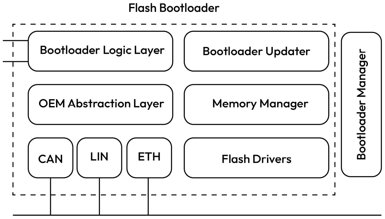
Figure 1.7 – Block diagram of a typical bootloader architecture
At startup, the flash bootloader performs basic hardware initialization and may control which software partition is executed based on the partition validation check results. Manipulating this stage can result in the startup of a tampered application or the improper safety and security initialization of the system. During runtime, the bootloader provides the functionality to reprogram the software and calibration images either through a diagnostic client or through an over-the-air (OTA) application. Illegal access to the flash bootloader update mechanisms can result in the ECU being programmed with unsafe or maliciously crafted software. Let’s assume the bootloader manages two partitions – one that contains a backup image and one that contains a recently updated image that must be booted. The bootloader memory flags that determine which software partition to boot after reset are critical for security because if they’re tampered with, this can result in the execution of an invalid or corrupt software image. Additionally, flash drivers containing the routines to erase and reprogram flash contents are important for security as they can be misused to reprogram or erase the ECU software or calibration data.
Discussion point 5
Investigate the software layers of the bootloader to see whether you can spot any services that can be abused by an attacker so that they can reprogram or erase the software.
Once again, let’s turn our attention to our SoC-based ECUs and look inward at the software architecture. Luckily, AUTOSAR has also standardized a software architecture that targets such systems through the AUTOSAR adaptive variant. While AUTOSAR adaptive has not reached the level of market adoption as AUTOSAR classic, it still serves as a useful reference. A key feature of this software architecture is the transition from signal-based software design to a service-oriented architecture (SOA). Rather than a monolithic software image built for a specific ECU with a pre-generated RTE, AUTOSAR adaptive offers a flexible architecture that allows for dynamically updated and deployed applications. Another key feature is its reliance on high-bandwidth networking technologies such as Ethernet:
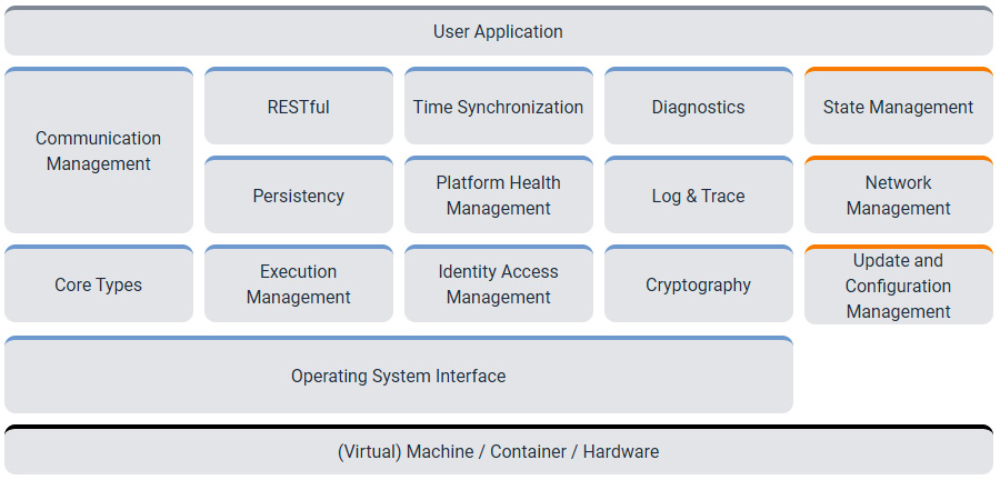
Figure 1.8 – AUTOSAR adaptive block diagram (credit: AUTOSAR)
The adaptive architecture offers the main set of basic services needed to enable computationally intensive user applications. Rather than defining its own operating system, AUTOSAR adaptive defines an operating system interface layer that is compatible with any POSIX PSE51-compliant operating system. This ensures the portability of the AUTOSAR adaptive implementation across various operating systems and hardware platforms. The POSIX PSE51 profile represents the core set of POSIX APIs, which include support for features such as thread priority scheduling, thread-safe functions, synchronized I/O, real-time signals, semaphores, shared memory, inter-process communication (IPC) message passing, as well as a few utilities. Moreover, AUTOSAR adaptive can be hosted directly on a single hardware platform or as a virtual machine, sharing the platform with other operating system instances. A brief look at the AUTOSAR adaptive software architecture shows several security-related concepts. For one, data read or written to the non-volatile storage through the persistency cluster can be considered security-relevant. Error information reported through the platform health management cluster to enable the user application to take safe action is also worthy of protection. Communication data handled through the communication management cluster is another interesting area to consider when you’re analyzing the security of an adaptive-based system.
Discussion point 6
How about the logs captured by the Log and Trace cluster? What does the cryptography cluster manage, and could these assets be vulnerable? How about the Update and Configuration Management cluster?
Before we finish this section, we must look at how SoC-based ECUs are booted and updated:
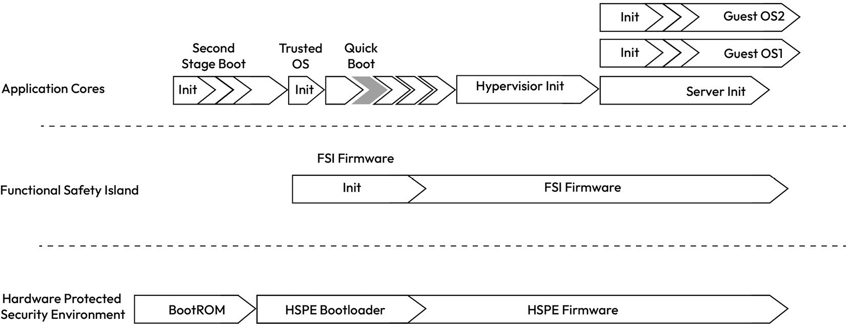
Figure 1.9 – Example boot flow from a typical SoC
Unlike the flash bootloader of the MCU-based ECU, SoC-based ECUs rely on a series of bootloaders that load software and calibration data from the external non-volatile memory into DRAM and other internal volatile memory types before handing control over to the respective cores that run the loaded firmware and software. The boot process typically starts with a MaskROM boot partition, which performs the initial hardware configuration, loads the next boot stage, and then jumps to the next boot partition after verifying its integrity and authenticity (assuming secure boot is enabled). This process continues until all firmware is booted in a staged fashion up to the point where the hypervisor kernel is started (if multiple virtual machines are supported). The hypervisor, using a loader utility, then loads one or more guest operating systems in memory and allocates the necessary CPU, memory, and hardware resources to allow the guest operating system to function as an isolated virtual machine. The latter is then responsible for launching its applications and managing its resources. Alternatively, if the operating system is running directly on the hardware (also known as a host OS), then a hypervisor is not needed. The boot sequence is one of the most security-critical execution paths of the ECU because any exploitable weakness in the boot chain can result in the execution of malicious software, which can spell disaster for a safety-critical ECU.
When it comes to reprogramming the firmware and software binaries, different types of update solutions exist, including OTA. AUTOSAR adaptive provides one reference architecture through its update and configuration management cluster. This enables updates through a diagnostic client in addition to an OTA application. As you might have guessed, this functionality is also security-critical as it exposes the software platform to the possibility of malicious software updates and the execution of potentially dangerous code.
Now that we have been introduced to the general hardware and software architecture of ECUs, let’s explore the various ECUs and the domains in which they are grouped based on their related functionality. This will prove useful in later chapters as we analyze the threats that impact such ECUs.