

The Serial Peripheral Interface (SPI) protocol implements a synchronous serial link between a master and a slave. When a single slave is used, only three signals (and ground) are needed.
The master generates an SCLK (serial clock) clock signal, which is sent to the slave. On some transitions of this clock, the slave will read data using the appointed signal, MOSI (short for master out, slave in), or write it using the signal named MISO (master in, slave out). There are several names, depending on hardware manufacturers, used to describe these signals. It is recommended to use the MISO/MOSI notation (the most common one), because it removes any ambiguity: the MOSI pin of a master must always be connected to the MOSI pin of a slave, and the same is true for the MISO pin.
If several slaves are to be connected to the same host, they may be connected in parallel (all MISO pins connected together as well as all MOSI pins), but an additional signal (CS, or Chip Select) is required for...
The i2c protocol enables us to port a master component (usually the microprocessor) and several slave devices. Several masters can share the same bus, and the same component can send slave status to the master or vice versa. However, communication takes place only between the master and one slave. Note also that the master can send a command to all slaves simultaneously (such as a sleep or reset request).
At the electrical level, the protocol uses signals alternating between high and low levels; the most common value pairs are (0, 5V) and (0, 3.3V). The SCL clock signal is generated by the master. The serial data (SDA) data signal is set high or low by the master or slave, according to the communication phase. Throughout the duration of the high segment of the SCL clock, the SDA data signal must be kept high or low, depending on whether it transmits a 1 or a 0.
Finally, as shown in the following figure, particular configurations of signals (produced by the master) can indicate...

The Nunchuck has an X/Y joystick, an X/Y/Z accelerometer, and two buttons (Z and C).
The sensor data is communicated through the i2c bus.
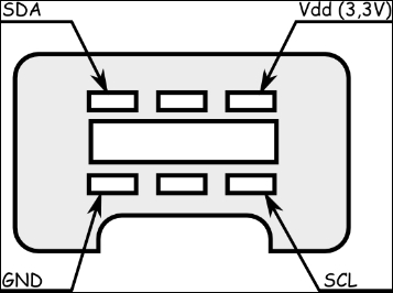
The connector contains four wires, two of which are power and ground. The other wires are used for i2c communication (SDA and SCL). The following diagram demonstrates the principle:
Note
If you are worried about your connection, you can find an adapter for this controller at https://www.sparkfun.com/products/9281.
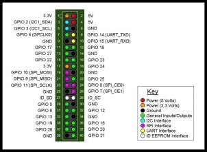
For the connection with our Raspberry Pi, we just have to connect it to the main connectors, I2C1_SDA and I2C1_SCL, as shown in this pin diagram:
The Wii Nunchuck contains a controller that communicates through the i2c bus. In order to know where to store bytes written to it, the first byte must be an 8-bit register address. In other words, each write() operation to the Nunchuck requires one register address byte, followed by data bytes.
For a write operation, the first byte sent to the Nunchuck tells it where to start (the START condition).
The Nunchuck is designed to provide a specific encrypted link. However, this can be disabled through the following process:
Write 0x55 to the Nunchuck's 0xF0 register
Pause
Write 0x00 to the Nunchuck's 0xFB register
|
Write |
Pause |
Write | ||
|
0xF0 |
0x55 |
- |
0xFB |
0x00 |
Note that if you own a white Nunchuck, the process will be different:
Write 0x00 to the Nunchuck's 0x40 register
|
Write | |
|
0x40 |
0x00... |