In this section, we will be creating our very first basic scene using Geometry Nodes. You will learn how to add the Geometry Nodes modifier to your base mesh and how to instance an object onto each vertex of your base mesh. We will look at some of the nodes that you can use to manipulate these instances such as Position, Scale, and Rotation. Additionally, you will learn how to randomize certain attributes, and we will also take a look at the different types of attributes and how they are used.
Let's begin by creating a new Blender project.
Creating the base mesh
Let's begin by creating our base mesh. For this example, we will be creating a plane object and applying the Geometry Nodes modifier to it. Then, we will use this plane object to distribute instances of another object across it:
- Click on File and select New | General.
- Delete everything in your scene by pressing A and then pressing X. Click on Delete to confirm. You now should have a blank new scene. Now feel free to save your project!
- Create a plane by pressing Shift + A and selecting Mesh | Plane.
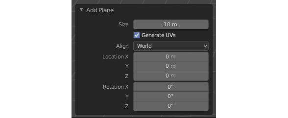
Now, let's scale our plane.
- Select the plane, press S, then 10, and then Enter. This will scale your plane to a size of 10 m x 10 m. It's always good practice to select Apply your scale whenever you modify the scale of an object in Blender, especially if you will be adding any modifiers to that mesh.
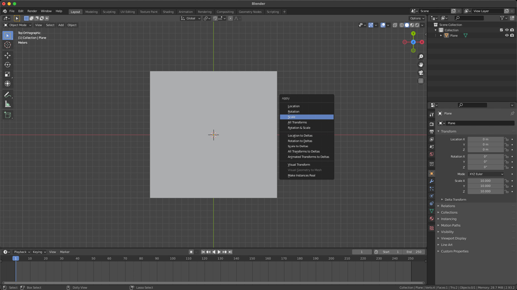
- To do this, select the plane, press Ctrl + A, and then select Scale from the drop-down menu. This will apply the scale factor and reset the object's scale to 1:
Figure 1.4 – Applying the scale to your plane
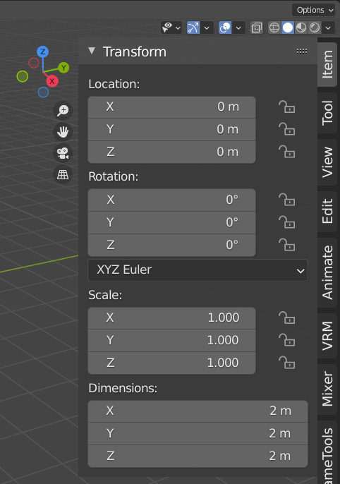
- You can view the scale factor by selecting your plane and pressing the N shortcut to open the side menu. In the Item tab, underneath Transform, you will see the Scale factor, which should currently be X: 1.000/Y: 1.000/Z: 1.000:
Figure 1.5 – The scale of the plane set to 1/1/1
Creating a new Geometry Nodes modifier
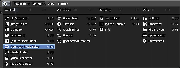
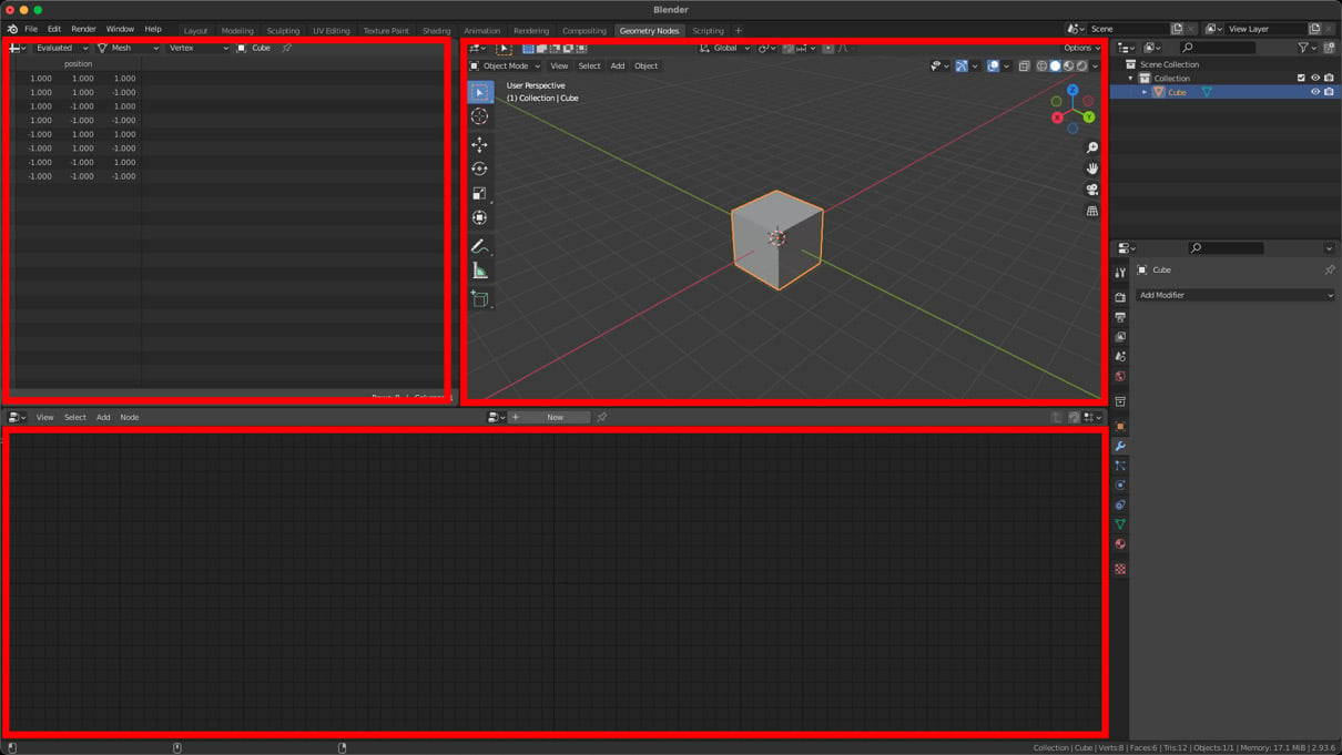
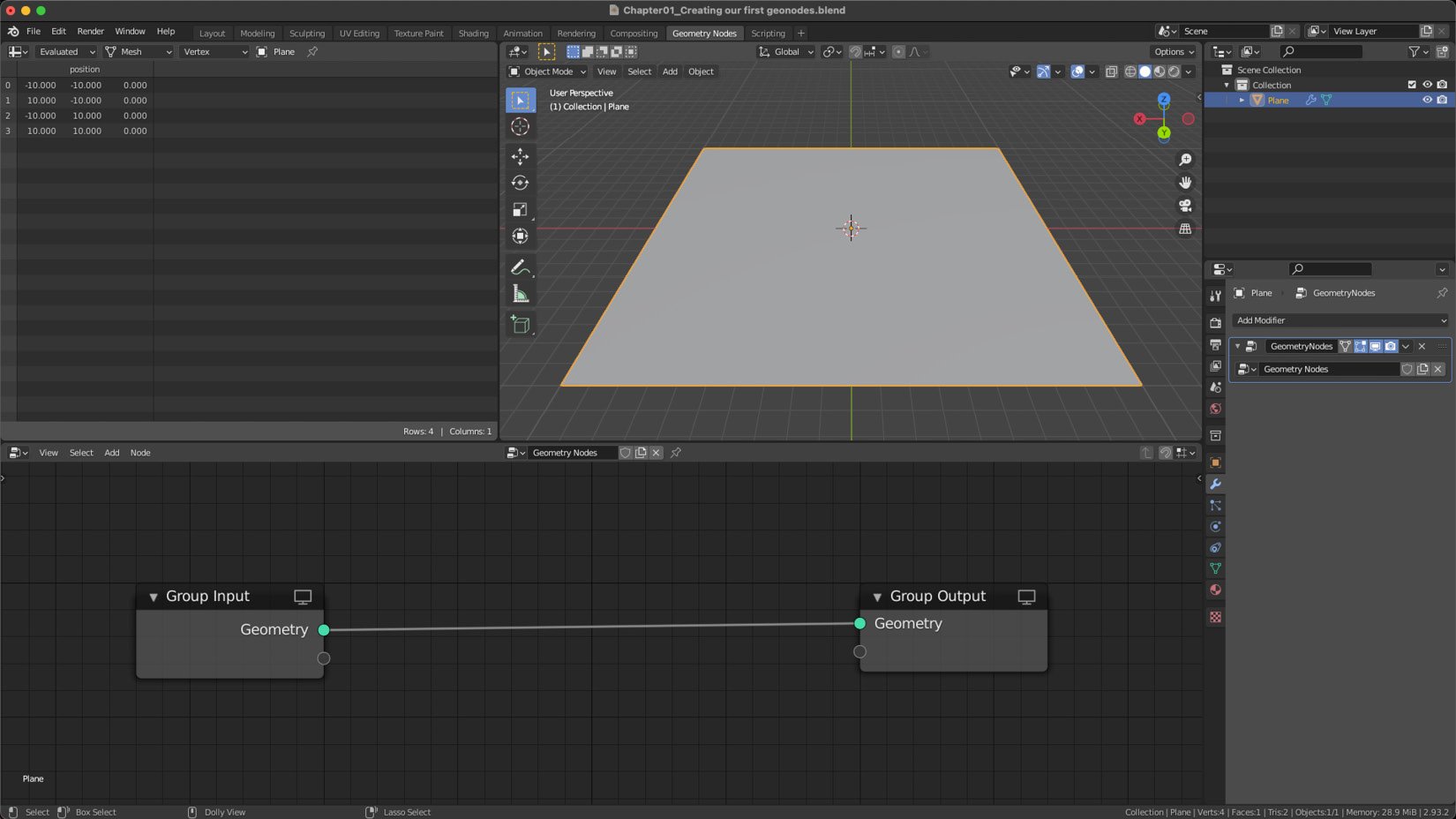
Now, let's open the Geometry Nodes workspace by clicking on the tab at the top of the Geometry Nodes interface. You will now see the Geometry Nodes workspace split into three main views: the 3D Viewport window (in the upper-right corner), the Spreadsheet window (in the upper-left corner), and the Geometry Node Editor window at the bottom. Perform the following steps:
- To create our first Geometry Nodes system, let's click on our plane to select it.
- Click on the NEW button at the top of the Geometry Node Editor:
Figure 1.6 – The Geometry Node Editor
Congratulations! You have created your first Geometry Nodes setup! You will see two nodes that have been added automatically: the Group Input node and the Group Output node.
It's important to note that your data will always flow from the Group Input node on the left-hand side to the Group Output node on the right-hand side. Everything between these two nodes will modify our geometry.
Creating our instance object
Before we start adding any nodes to our node setup, we need something to use as our instance object. So, let's create a mesh that we can use:
- With your mouse pointer over the 3D Viewport window (in the upper-right corner), press Shift + A and select Mesh | Icosphere.
- Select the Icosphere instance in the 3D Viewport window, press G, and then press X to move it along the X axis away from the plane.
In the next section, we will use this Icosphere node as an instance object.
Creating our first nodes
Let's begin adding some nodes! In this section, we will look at how you can add new nodes to the node tree and how to distribute your instance object across your base mesh:
- Click on the plane object in the 3D Viewport window to select it.
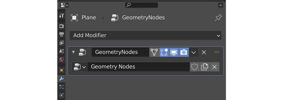
With your Icosphere instance out of the way and your plane selected, you should now see two nodes in the Geometry Node Editor. If you don't see any nodes, make sure that the Geometry Nodes modifier is selected or has been highlighted in the modifiers panel on the right-hand side:
Figure 1.7 – The Geometry Nodes modifier
- With your mouse pointer over the Geometry Node Editor window, press Shift + A to access the Node Add menu.
- Hover over the Point category and click on Point Instance to create your first node.
- Click anywhere to place your node.
- Now, let's drag our new node onto the line that connects the Group Input node and the Group Output node.
- Additionally, you can zoom in and out by scrolling the mouse wheel and pan by holding down the mouse wheel.
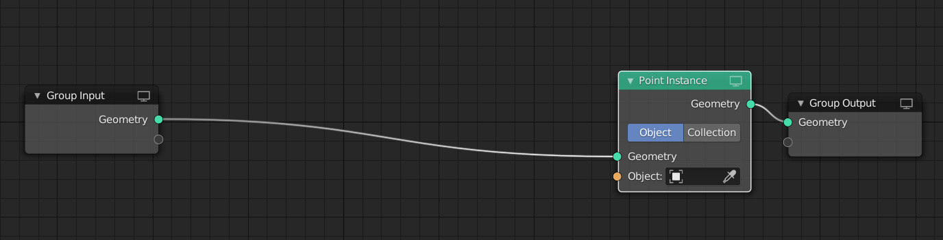
- Move your Point Instance node closer to the Group Output node as we will be adding new nodes, mainly between the Group Input node and the Point Instance node, in this example:
Figure 1.8 – Your node tree should now look like this
Nodes that change attributes should almost always be placed before the Point Instance node, as the points are not referenced after this node.
Specifying the instance object
Note that your plane object has disappeared in the 3D Viewport window! The reason for this is that we have not yet specified an instance object for our Point Instance node.
Let's do this now:
- Click on the Object drop-down menu on the Point Instance node to select the Icosphere mesh object that we created from the list earlier:
Figure 1.9 – The Point Instance node
- You can also click on the eyedropper icon and select the Icosphere object that way.
Now, let's take a look at what has happened in the 3D Viewport window:
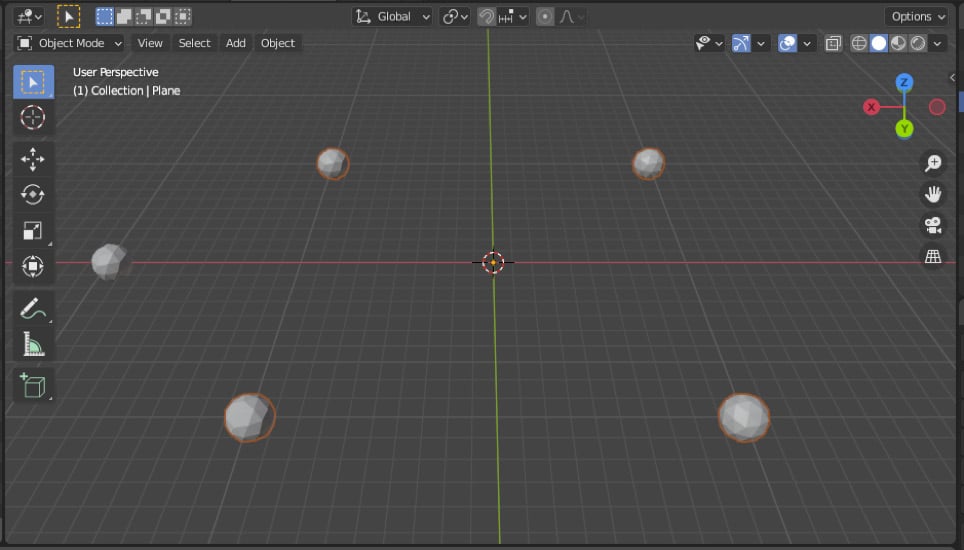
Figure 1.10 – Instances are placed on each vertex of the plane
As you can see, we now have four Icosphere instances. Ignore the original Icosphere instance that we moved off to the side – you can even hide it if you want. The reason we see four Icosphere instances is that our plane has four vertices. It's creating an instance on each vertex. Let's increase the number of vertices by subdividing our plane. We can do this right inside the Geometry Node Editor as there is a Subdivide node that we can use.
The Subdivide node
The Subdivide node will increase the number of points or vertices on our base mesh. Let's examine how we can use it in our scene:
- Press Shift + A to access the Add menu, point to the Mesh category, and click on the Subdivide node.
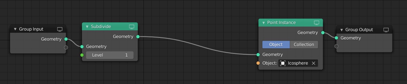
- Move the node and place it on the line just right of the Group Input node:
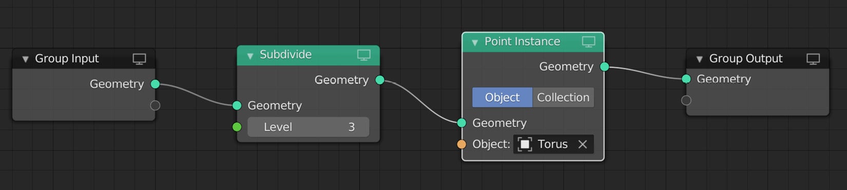
Figure 1.11 – Your node tree should now look like this
Notice that you now have nine Icospheres in your scene. The reason for this is that our plane now has nine vertices because of the Level 1 Subdivide node.
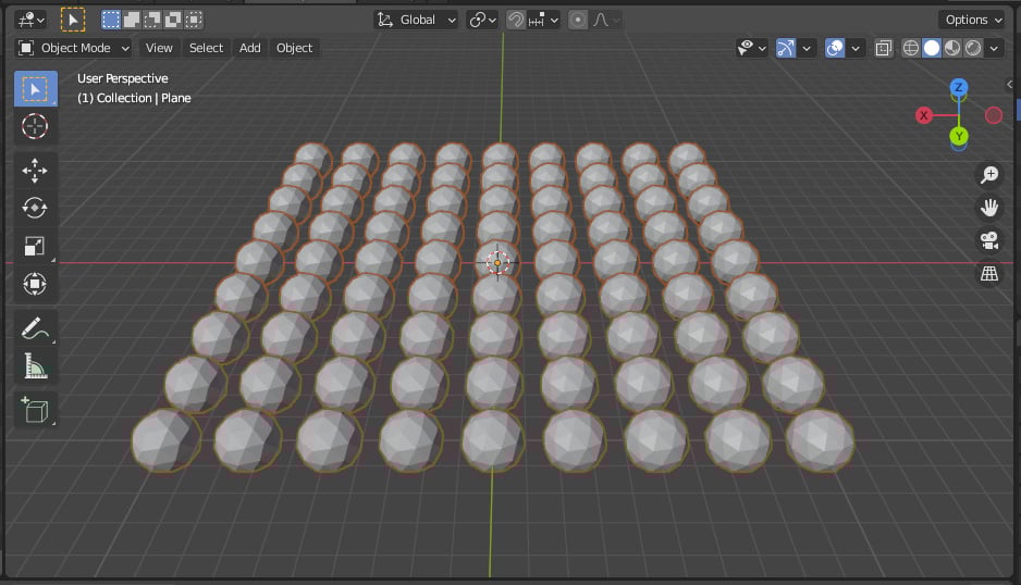
- Change the subdivision Level value to
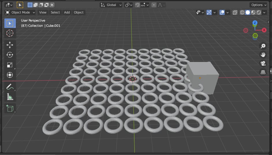
3. Now you should see a total of 81 Icospheres because we have increased the number of vertices on our plane to 81:
Figure 1.12 – Increasing the number of vertices will increase the number of instance objects
The Point Scale node
Now, let's change the scale of our Icospheres – there is a node for that, too! Let's add a Point Scale node:
- Press Shift + A and select Point | Point Scale.
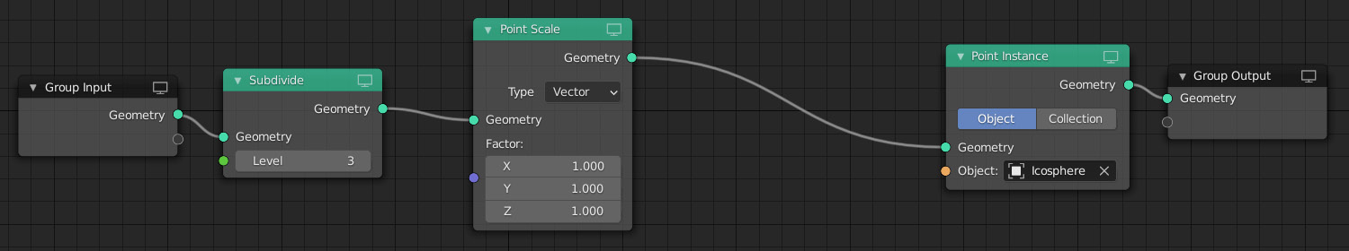
- Slot it in right after our Subdivide node:
Figure 1.13 – Your node tree should now look like this
Additionally, you can search for nodes without needing to know where to find them. When you press Shift + A to bring up the nodes menu, click on the Search option at the top and type in the name of the node you are looking for.
Notice that on the Point Scale node, you have access to three different numbers: X, Y, and Z. This is called a vector as it's a set of three numbers. Change one of the numbers by clicking on it and dragging sideways. You will see how the scale of your Icospheres changes according to the axis you scale on. Let's change the Type setting from Vector to Float.
- Click on the drop-down menu next to Type and select Float from the list. Now you only have one number to change, which will scale your Icospheres uniformly.
- Click and drag the Factor value to adjust the size of the instance. For now, set it to any size you like.
We have now set the scale of our instance objects using the Point Scale node. In the next section, we will look at the different types of attributes available in Geometry Nodes.
Different types of attributes
Let's take a moment to look at the different types of attributes and data types that you will see:
- Integer: An integer is a number that can be written without a fractional component.
- Float: A float is a floating-point number, which means it is a number that has a decimal place.
- Vector: A vector is a set of three float numbers and is mostly used to calculate a position in world space.
- Boolean: A Boolean only has two values and can be used for something that's either
true or false.
- Attribute: This is a text field to input an attribute name.
The most commonly used attributes are Position, Scale, and Rotation (these are all vector-based as they consist of three numbers, which each correspond to the three axes of X, Y, and Z). However, there are also a few others that we will look at in later chapters.
The Point Rotate node
Let's look at how we can rotate our objects. To do this, we will need a new node called Point Rotate. Let's add it to our tree:
- Press Shift + A and select Point | Point Rotate (or you can use the search function).
- Add this node to the right-hand side of the Point Scale node:
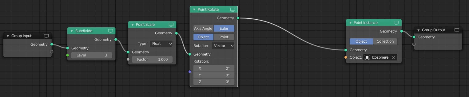
Figure 1.14 – Your node tree should now look like this
You will see that the Point Rotate node uses a Vector data type because you can rotate using the different X, Y, and Z axes.
Click and drag the values next to the different axes to see how your Icospheres rotate in your scene. Please note that the difference between Object and Point is that Object will rotate every point in the local space of the object, while Point will rotate every point in its local space as specified by its Rotation attribute.
The Point Translate node
Next, let's take a look at how to change the position of our objects. For this, we need the Point Translate node. Let's add it now after our Point Rotate node:
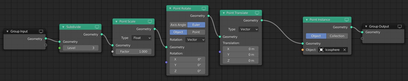
- Press Shift + A and select Point | Point Translate or use the search function. Again, you will see that it uses a vector as we can translate in either X, Y, or Z.
- Drag the values next to X, Y, and Z to see all of your Icospheres moving along that axis:
Figure 1.15 – Your node tree now looks like this
The Attribute Randomize node
Our scene still looks very uniform and a bit boring; however, Geometry Nodes allows you to easily randomize your attributes! Let's see how we can randomize the Scale attribute of our Icospheres. For this, we will need a node called Attribute Randomize.
Let's add it now:
- Press Shift + A and select Attribute | Attribute Randomize to add the node.
- Place it on the right-hand side of the Point Translate node:
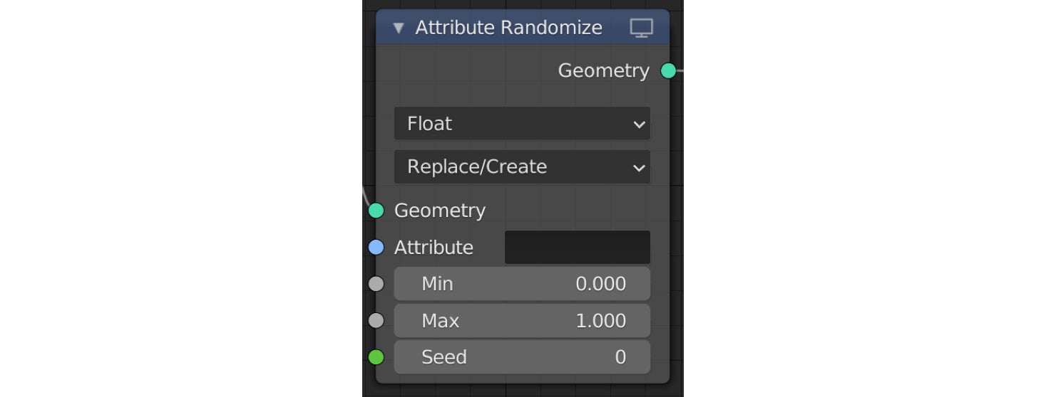
Figure 1.16 – The Attribute Randomize node
This node is slightly more complex, as we can choose which attribute it will randomize and how it will influence the current attribute values.
Let's examine how we can randomize the Scale attribute.
Randomizing the Scale attribute
We can use the Attribute Randomize node to randomize different attributes. Let's see how we can randomize the Scale attribute of our instance objects:
- Click on the empty box next to Attribute. You will see a list of available attributes that we can use.
- Select Scale from the list. Instantly, you will see that all of your Icospheres now have different sizes! Additionally, you can type in the attribute name in the empty box. However, note that the attribute names are case sensitive, so be aware of this when typing in an attribute name rather than selecting it from the drop-down list.
- The Min and Max float numbers determine the range of randomness. Change these numbers to see how they affect your scene. (Tip: Hold Shift while dragging these values to have more accurate control.)
The default data type value is set to Float, which means we use one number for all three axes, which will result in a uniform scale.
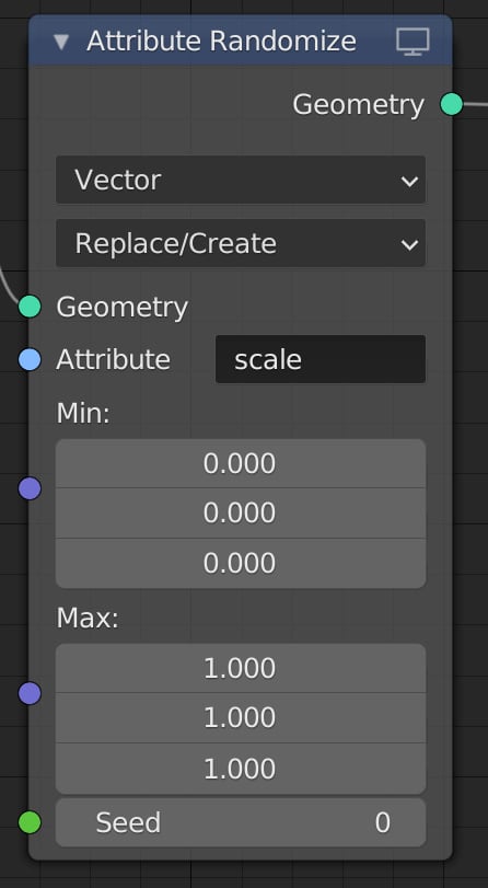
- Change this to Vector by clicking on the drop-down list at the top of the node and selecting Vector:
Figure 1.17 – The Attribute Randomize node
Now we have much more control over how our instances will be scaled. We can adjust the minimum and maximum values for all three X, Y, and Z axes.
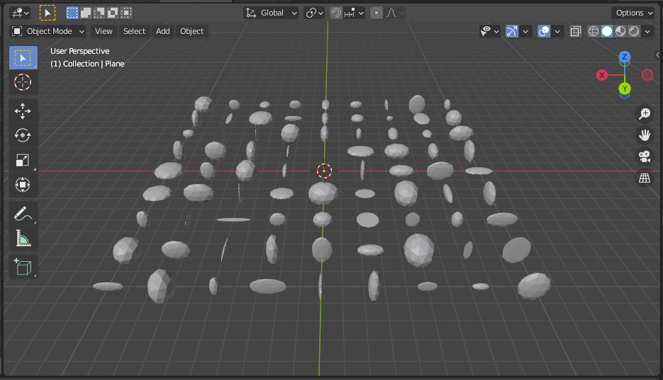
- Adjust the three values under Min and Max to see how this affects your scene and how the scaling is no longer uniform by adjusting these values:
Figure 1.18 – The 3D Viewport window showing non-uniform scaling because of the vector
- This might be the desired effect you are going for, but let's change the data type back to Float so that we're scaling our instance uniformly.
- Set the Min value to
0 and the Max value to 1. Notice that some of the Icospheres are not being displayed or might be very tiny. This is because we're using the Replace/Create operator, which means we're choosing a value between 0 and 1 and replacing the current Scale attribute with this new number. Note this value can be 0, which will result in some Icospheres with a scale of 0, making them disappear.
- Change the operator setting from Replace/Create to Add.
Now we are adding our random value to the current Scale attribute, which will not result in Icospheres with a scale of 0. Other operators you can use are Multiply and Subtract, which work in a similar way to the Add operator.
Randomizing the Position attribute
Let's randomize the position of our Icospheres!
This time, we're going to duplicate our Attribute Randomize node and reuse it for the Position attribute:
- Click the current Attribute Randomize node to select it.
- Press Shift + D to create a duplicate copy.
- Drag the new copy to the right-hand side of the current Attribute Randomize node:
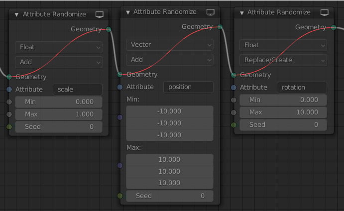
Figure 1.19 – The Attribute Randomize node
Let's configure the node as follows:
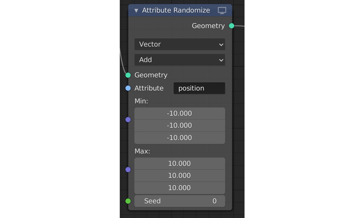
- Change the data type to Vector. The reason for this is that we want to randomize the X, Y, and Z positions for each instance.
- Set the Operator setting to Add.
- Select the position attribute from the Attribute drop-down box, or you can simply type
position into the box. Please note that attribute names are case sensitive:
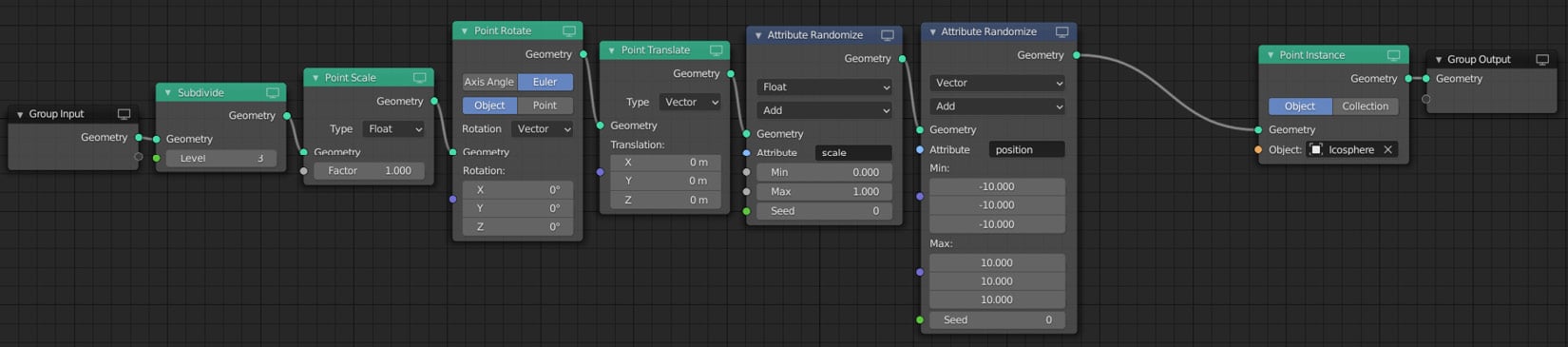
Figure 1.20 – Your node tree should now look like this
- Set your Min value to
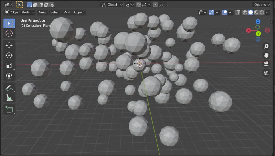
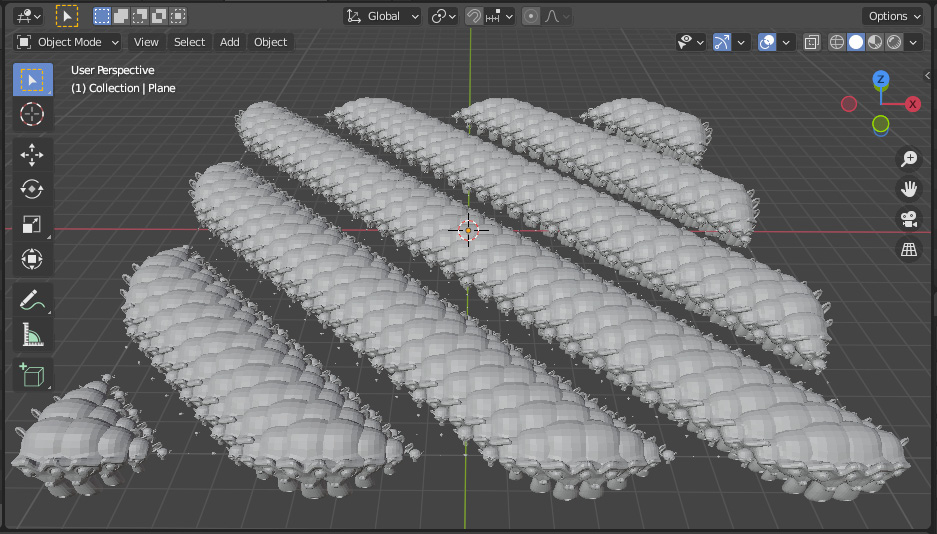
-10 and Max value to 10. This will randomize our Icospheres' positions from -10, -10, and -10 to 10, 10, and 10 in world space:
Figure 1.21 – The 3D Viewport window showing the randomized positions
Randomizing the Rotation attribute
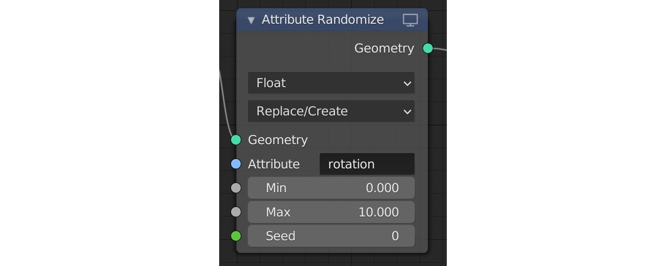
Let's randomize the rotation of our Icospheres. For this, we will again duplicate our Attribute Randomize node and place it on the right-hand side of the position Attribute Randomize node:
Figure 1.22 – The Attribute Randomize node
Let's configure this node as follows:
- Change the data type to Float. The reason we're using a float is that we want to use one value to rotate our instance in all axes. You can use a vector to have exact control over how we rotate. However, for this example, we're going to use a float.
- Change the Operator setting to Replace/Create.
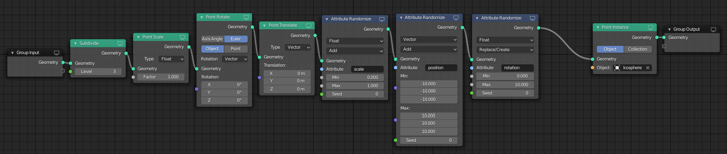
- Change the Attribute setting to rotation:
Figure 1.23 – Your node tree and scene should now look like this
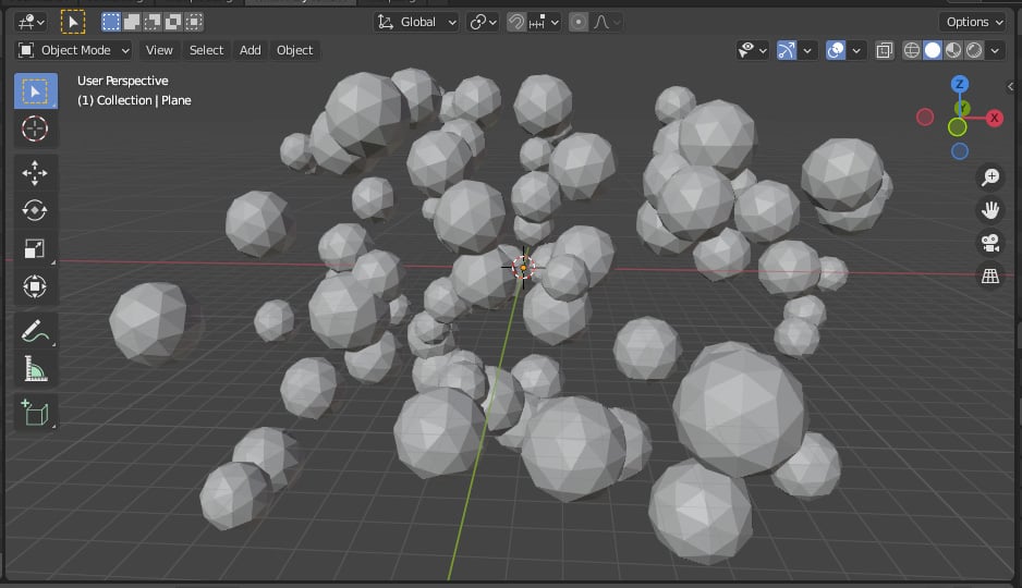
- Set the Min value to
0 and the Max value to 10:
Figure 1.24 – The 3D Viewport window showing randomized rotations
Changing the instance object
It's very easy to change your instance object into something else. Let's do that now.
Start by creating a new instance object in our scene. For this, we will be adding a Suzanne object:
- With your mouse pointer over the 3D Viewport window, press Shift + A and select Mesh | Monkey.
- Move the Suzanne mesh to the side of our scene by pressing G and then pressing X.
- Click on one of the Icospheres to view your Geometry Nodes.
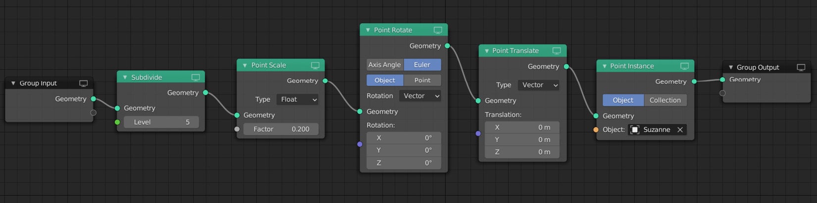
- Click on the Point Instance node to select it.
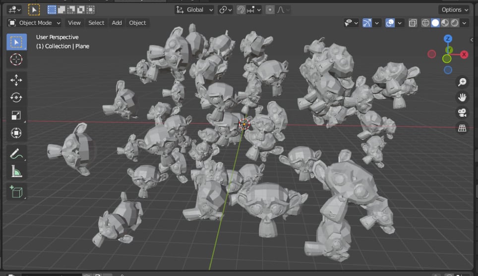
- Click on the Icosphere item next to Object and select Suzanne from the drop-down list:
Figure 1.25 – The Point Instance node
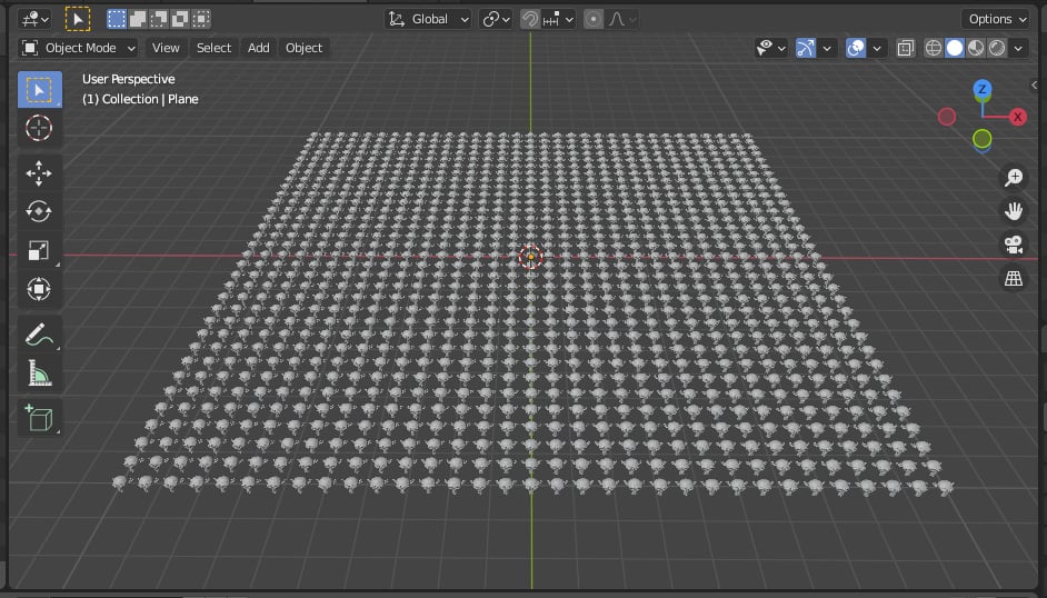
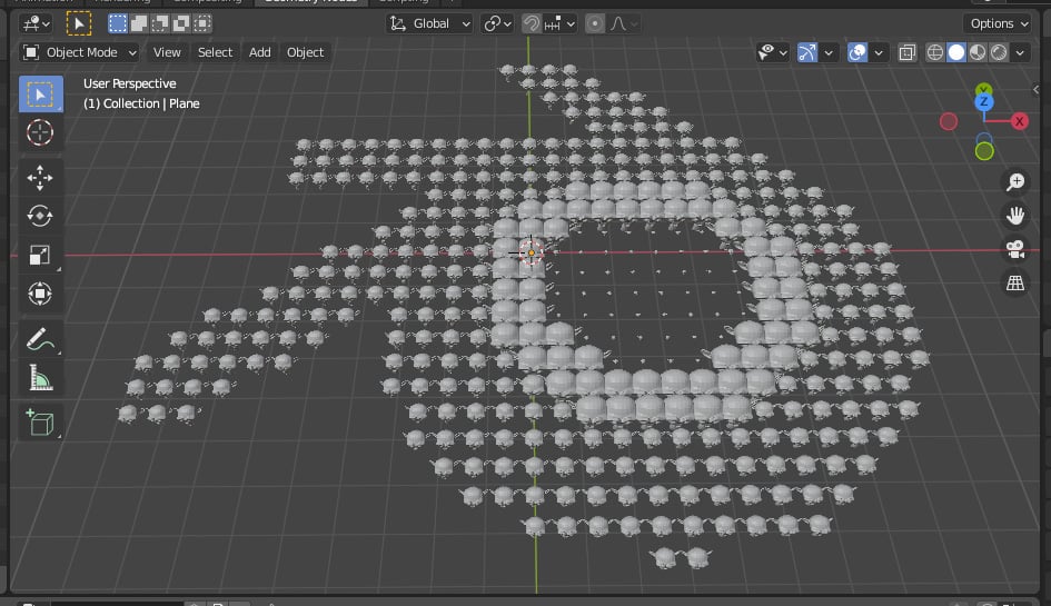
Now, let's take a look at what happened in the 3D Viewport window:
Figure 1.26 – Updated instances in the 3D Viewport window
Muting nodes
You can also mute or deactivate certain nodes to see exactly what they do. This is good practice for troubleshooting your node tree. To do this, highlight the node or nodes you want to mute and press the M shortcut.
Now, let's mute our three Attribute Randomize nodes:
Figure 1.27 – Muting nodes by selecting them and pressing M
Observe how your scene will update instantly! You can unmute/reactivate these nodes again by selecting them all and pressing M again.
Congratulations! You have now created your first basic scene using Geometry Nodes. Please save your project now, as we will continue to work on it during the next section.
 Argentina
 Australia
 Austria
 Belgium
 Brazil
 Bulgaria
 Canada
 Chile
Chile
 Colombia
 Cyprus
 Czechia
 Denmark
 Ecuador
 Egypt
Egypt
 Estonia
 Finland
 France
 Germany
 Great Britain
 Greece
 Hungary
 India
India
 Indonesia
 Ireland
 Italy
Italy
 Japan
Japan
 Latvia
 Lithuania
 Luxembourg
 Malaysia
 Malta
Malta
 Mexico
 Netherlands
 New Zealand
 Norway
 Philippines
 Poland
 Portugal
 Romania
 Russia
 Singapore
 Slovakia
 Slovenia
 South Africa
 South Korea
 Spain
Spain
 Sweden
 Switzerland
 Taiwan
 Thailand
 Turkey
 Ukraine
 United States