Interfacing the MPU-9250 with the Arduino and ROS
So the first step in this project is to interface the IMU to the Arduino to get the rotation values and send those values to ROS. We're essentially making an Arduino-ROS node that is receiving IMU values and publishing the yaw, pitch, and roll as well as the transformation (TF) corresponding to the IMU movement as ROS topics.
The following figure shows the interfacing of IMU with the Arduino. The IMU is interfaced using the I2C protocol:
Figure 7: Interfacing MPU 9250/9150/6050 with Arduino
The connection from Arduino to MPU-9250 is shown in this table:
To start working on IMU values in ROS, we have to create a ROS-Arduino node that is receiving IMU values and send it as ROS topics. I hope you have set up the Arduino IDE in your system. For running this code, you will need the Arduino library for the MPU - 9250. Note that you can use the MPU...
Visualizing IMU TF in Rviz
In this section, we are going to visualize the TF data from Arduino on Rviz. Here's the procedure to do that.
Plug the Arduino to the PC and find the Arduino's serial port. To get topics from the Arduino-ROS node, we should start a ROS serial server on the PC, listening on the Arduino serial port. We did this in Chapter 4, Controlling Embedded Boards Using ROS. Still, let's look at the commands again in this section too.
Starting roscore first:
$ roscore
Starting the ROS serial server:
$ rosrun rosserial_python serial_node.py /dev/ttyACM0
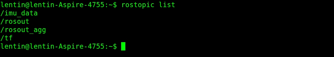
You can get the following topics when you run the previous node:
Figure 9: Listing ROS topics from Arduino
You can simply echo these topics, or visualize the TF data on Rviz. You can run Rviz using the following command. The base_link option is the fixed frame, and we can mention that on the command line itself.
$ rosrun rviz rviz -f base_link
The Rviz window will pop up, and if there is no TF option on the left-hand side of Rviz...
Converting IMU data into twist messages
If you are able to the visualization in Rviz, you are done with the interfacing. The next step is to convert IMU orientation into command velocity as ROS twist messages. For this, we have to create a ROS package and a Python script. You can get this package from chapter_5_codes/gesture_teleop; look for a script called gesture_teleop.py from the gesture_teleop/scripts folder.
If you want to create the package from scratch, here is the command:
$ catkin_create_pkg gesture_teleop rospy roscpp std_msgs sensor_msgs geometry_msgs
Now let's look at the explanation of gesture_teleop.py, which is performing the conversion from IMU orientation values to twist commands.
In this code, what we basically do is subscribe to the /imu_data topic and extract only the yaw and pitch values. When these values change in the positive or negative direction, a step value is added or subtracted from the linear and angular velocity variable. The resultant velocity is sent using...
Integration and final run
We are almost done! But how to test this teleop tool? We can create some launch file that can start all these nodes and work with some robot simulation. The gesture_teleop/launch folder has three launch files. Let's take a look at them.
The gesture_teleop.launch file is a generic launch file that can be used for any robot. The only thing we need to edit is the command velocity topic. Here is the definition of this launch file:
     <launch>
        <param name="teleop_topic" value="/cmd_vel"/>
        <rosparam command="load" file="$(find
           gesture_teleop)/config/teleop_config.yaml"/>
      <node name="rosserial_server_node" pkg="rosserial_python"
          type="serial_node.py" args="$(arg port)" output="screen"/>
      <node name="gesture_teleop_node" pkg="gesture_teleop"
          type="gesture_teleop.py" output="screen"/>
     </launch>
This launch file...
Teleoperating using an Android phone
If it is difficult to build the previous circuit and set everything up, there is an easy way to do so with your Android phone. You can manually control either using a virtual joystick or the tilt of the phone.
Here is the Android application you can use for this:
https://play.google.com/store/apps/details?id=com.robotca.ControlApp.
The application's name is ROS Control. You can also search on Google Play Store for it.
Here is the procedure to connect your Android phone to a ROS environment:
Initially, you have to connect both your PC and Android device to a local Wi-Fi network in which each device can communicate with each other using IP addresses.
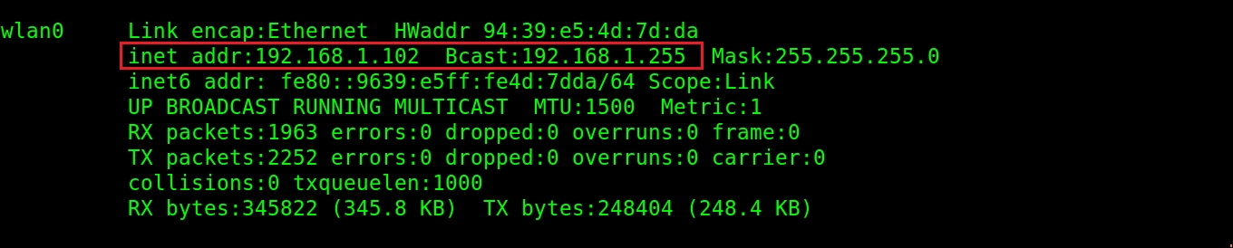
After connecting to the same network, you have to start roscore on the PC side. You can also note the IP address of the PC by entering the command ifconfig.
Figure 13: Retrieving the IP address of a PC with ifconfig
After obtaining the IP address of the PC, you can start the app and create a robot configuration...
This chapter was about making a gesture-based teleoperation project for a ROS-based robot. We used an IMU to detect gestures and interfaced with the Arduino to get the values from the IMU. The Arduino is interfaced with ROS using the ROS serial protocol. The PC is running a ROS node that can convert IMU orientation into linear and angular velocity and send it as a twist message. This twist message can be used in any robot just by changing the teleop topic name. We can also visualize the IMU orientation data in Rviz using TF data from Arduino. If it is too difficult to build this circuit, we can use an Android app called ROS Control that can move the robot using the inbuilt IMU on the phone.
In the next chapter, we'll be dealing with 3D object recognition using ROS.