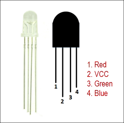
Changing color through an RGB LED
The last demo of basic LED programming is to work with an RGB LED. This LED can emit monochromatic light, which could be one of the three primary colors—red, green, and blue, known as RGB.
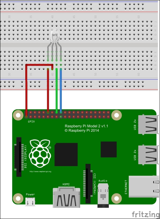
The RGB LED connection is shown in the following figure:
In this section, we will build a simple program to display red, green, and blue colors through the RGB LED.
The following hardware components are needed:
Our hardware wiring can be implemented as follows:
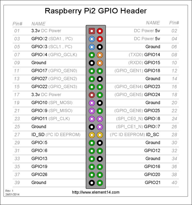
RGB LED pin 1 is connected to Raspberry Pi GPIO18
RGB LED pin 2 is connected to Raspberry Pi VCC +3 V
RGB LED pin 3 is connected to Raspberry Pi GPIO23
RGB LED pin 4 is connected to Raspberry Pi GPIO24
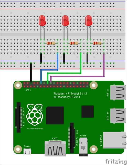
The complete hardware wiring can be seen in the following figure:
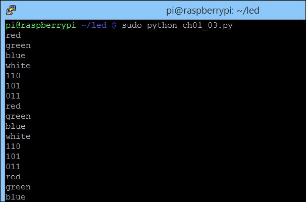
Returning to the Raspberry Pi terminal, you could write a Python program to display color through RGB LED. Let's create a file named ch01_03.py and write this script as follows:
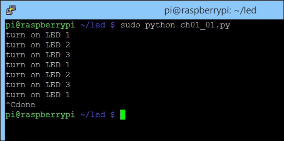
Save this script. You can run this file by typing the following command:
Then, you should see that the RGB LED displays a certain color every second. The program output can also write a message indicating which color is currently on the RGB LED:
The RGB LED can display a color by combining three basic colors: red, green, and blue. First, we initialize Raspberry Pi GPIO and define our GPIO usage:
For instance, to set a red color, we should set LOW on the red pin and HIGH on both green and blue pins. We define the display() function to display a certain color on the RGB LED with the red, green, and blue values as parameters as follows:
In the main program, we display a color via the display() function by passing red, green, and blue values, as shown in the following code: