Chapter 5. Building Your Own Traffic Light Controller
A traffic light controller is a signaling device positioned at road intersections and used to control road traffic. In this chapter, we will build a traffic light controller using Raspberry Pi.
You will learn the following topics in this chapter:
Introducing a traffic light controller
Designing a traffic light controller
Controlling AC/DC lamps using channel relay modules
Expanding Raspberry Pi GPIO
Building a traffic light controller
Cascading traffic light controllers
Introducing a traffic light controller
You can find traffic light controller devices at road intersections. They're used to manage vehicle movement on the road. Every traffic light consists of three lamps—red, yellow, and green. These colors have the following meaning:
Red: Drivers must stop their vehicle
Yellow: Drivers should prepare to start to drive or start to stop
Green: Drivers must drive their vehicle
A sample traffic light can be seen in the following figure:
These traffic lights are usually placed at the corner of a road intersection, as shown in the following diagram. You can see them on your left- or right-hand side. Sometimes, they're shown over the top of your vehicle:
In general, there can be two, three, four or n road intersections. We know that a traffic light needs three lamps, so to implement n road intersections, you need at least 3n lamps. You may need walking and do not work lamps. Some traffic road intersections can be seen in the following figure:
In this chapter, I will...
Designing a traffic light controller
To design a traffic light controller, you should identify what kind of road intersection model and connecting module among the lamps you want to build. For instance, if you want to build a traffic light controller for a four-road intersection, you need 12 lamps. This model needs at least 12 pins on Raspberry Pi GPIO.
In the real implementation process, lamps in a traffic light controller use AC as a power source, so you can't connect them to your Raspberry Pi board. It can be addressed by using a channel relay. A sample of a channel relay form can be seen in the following figure:
Some channel relay modules provide wireless links, such as radio, WiFi and XBee, which can be used by
Microcontrollers (MCUs) to control these modules, so you don't need cables to connect lamps to MCU.
Controlling AC/DC lamps using channel relay modules
A channel relay is a large mechanical switch. This switch is toggled on or off by energizing a coil. Wiring between the I/O control and the relay output does not connect with each other, so the MCU, which controls the I/O relay, is safe. For further information about how to use a relay, read the article available at http://www.circuitstoday.com/working-of-relays.
You can buy a channel relay module from your local electronics or online stores. The following are the online stores to get this stuff:
If you note a channel relay module, you should see some of the output pins, such as COM, N/A, NO, and NC, on the relay module body...
Expanding Raspberry Pi GPIO
Let's consider that you want to build a five-road intersection model. This means that you need at least 15 pins on Raspberry Pi GPIO. As you know, Raspberry Pi GPIO has limited pins, so we need to expand Raspberry Pi GPIO.
There are many approaches to expand Raspberry Pi 2. In Chapter 2, Make Your Own Countdown Timer, and Chapter 3, Make Your Own Digital Clock Display, we already learned how to expand Raspberry Pi GPIO via the shift register method. Now, you will see how to expand Raspberry Pi GPIO using another approach. Let's introduce the IC MCP23017. It's a 16-bit input/output (I/O) port expander with interrupt output and able to be cascaded for up to eight devices on one bus. The MCP23017 uses I2C for communication. Comparing with SPI, I2C uses a bus system with bidirectional data on the SDA line. Otherwise, SPI is a point-to-point connection with data in and data out on separate lines, MOSI and MISO. To communicate devices through I2C, you need to specify...
Building a traffic light controller
After having understood about a traffic light controller and learned how to use a channel relay and how to expand Raspberry Pi GPIO, you are ready to build a traffic light controller.
For testing, we will build a traffic light controller for four road intersections with the following scenario:
First, we set all intersections showing the red lamp
To execute traffic light 1, we turn on the yellow lamp and then turn on the green lamp
After this, we turn on the red lamp on traffic light 1
Repeat these steps for traffic lights 2, 3, and 4
The following hardware is needed:
A Raspberry Pi board
Twelve lamps with four red lamps, four yellow lamps, and four green lamps
A 4 x 3-channel relay module
An IC MCP23017
Cables
In this case, you can ignore channel relay modules if you use a +3 V/+5 V LED, so LEDs can be connected to the IC MCP23017 pins directly. To simplify this demo, we use DC LEDs and don't need many-channel relay modules.
To implement our wiring, you connect all...
Cascading traffic light controllers
You may want to control many traffic light controllers via one board, that is, Raspberry Pi 2. It's possible. You just expand Raspberry Pi GPIO according to your needs. In the previous section, we already learned how to expand Raspberry Pi GPIO using the IC MCP23017. How to work with more than one IC MCP23017?
You can implement it with the following configuration:
You can connect the SCL and SDA pins to the same pin for I2C
Set the module address (A0, A1, and A2) with different address, for instance, IC1 000 and IC2 111
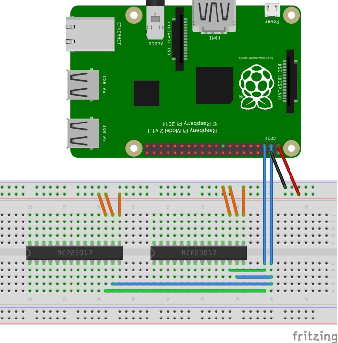
Now, you can connect the lamps to the IC MCP23017 output pins as usual. The following is a sample of the wiring implementation:
From the preceding figure, you can do construct the following wiring:
All IC MCP23017 SDA pins are connected to Raspberry Pi SDA
All IC MCP23017 SCL pins are connected to Raspberry Pi SCL
All IC MCP23017 VCC pins are connected to Raspberry Pi +5 V
All IC MCP23017 GND pins are connected to Raspberry Pi GND
The following...
We already learned about a traffic light controller. The chapter introduced a road intersection module at the start. A channel relay module is introduced in order to work with AC or high-voltage lamps. We also learned how to expand our Raspberry Pi GPIO. After this, we built a traffic light controller for four road intersections. In the last section, we tried to cascade our traffic controller by connecting several IC MCP23017.
In the next chapter, we will learn to control sensor or actuator devices via Bluetooth from a Raspberry Pi board.