


Lighting an external LED
Before we start to build a more complex circuit, let's begin with lighting up an external LED. As soon as this is working, we are going to extend the circuit step by step. We begin with a single red LED. Lighting up an external LED is a bit different compared to lighting up an onboard LED. We are going to need something on which we can place the LED, and we will need some wires as well as a basic understanding of resistors, which will help us to prevent the LED from taking damage. That is why we are going to look at each component one by one.
Using breadboards
Breadboards are used for prototyping, as they do not require you to directly solder components. We are going to build all our projects using breadboards.
A breadboard typically consists of two parts:
- The power bus
- Horizontal rows
Each side of a breadboard has a power bus. The power bus provides a + (positive) lane and a - (ground) lane. The positive lane is colored red and the ground lane is colored blue. The individual slots are connected inside the power bus.
The slots of a single horizontal row are also connected. A signal in one slot is also available in the next slot. Different horizontal rows are not connected, unless we put a cable in there to create a connection. Here's what a breadboard looks like:
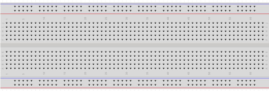
Figure 2.1 – A breadboard – image taken from Fritzing
Understanding LED basics
The Arduino UNO has an operating voltage of 5V, which is too high for most LEDs. So, we need to reduce the voltage to something our LEDs can handle. For that reason, we will be using 220 Ohm resistors to draw current from the line in order to protect the LED from damage. If you do not have 220 Ohm resistors, you can also use 470 Ohm as well; anything between 220 and 1K (1K = 1,000) Ohm will be fine.
If you want to really make sure that the resistor matches the needs of the LED, you can also calculate the resistor value as follows:
R = (Vs – Vled) / Iled
Where:
- R is the resistor value.
- Vs is the source voltage.
- Vled is the voltage drop across the LED.
- Iled is the current through the LED.
Note
LEDs have anode (+) and cathode (-) leads. The anode lead is longer.
Different colors need to be driven with different voltages. When using the same resistors and voltages for the different LED colors, you will notice that some colors will be brighter compared to others.
Using GPIO ports
GPIO stands for General Purpose Input Output. That means we can use these pins for input as well as output for digital signals. We can either set a GPIO pin to High or Low, or read a High or Low value from the port.
Note
We should never draw more than a maximum of 40.0 mA (milliampere) from a single GPIO port. Otherwise, we could permanently damage the hardware.
Building the circuit
Now let's build our first circuit on the breadboard:
- Put a red LED in the G column of the horizontal rows. Put the cathode in G12 and the anode in G13.
- Connect F12 with the ground lane on the power bus.
- Connect F13 and E13 using a 220 Ohm resistor. (Anything between 220 and 1,000 Ohms is okay.)
- Connect Pin 13 from the GPIO ports to A13.
- Connect the GND port to the ground lane on the power bus.
Note
The descriptions on your breadboard might differ from the ones I am using. If that is the case, you'll need to build the circuit by checking the next figure.
The circuit should now look like the following:
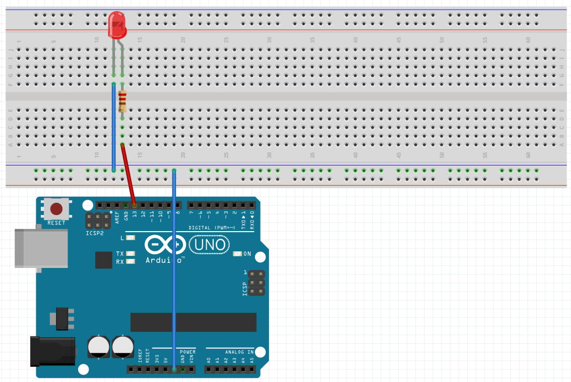
Figure 2.2 – Image of the circuit – image taken from Fritzing
Writing the code
We start off by creating a new folder named Chapter02 in our project workspace. This folder will be used for all parts of this chapter. Inside the Chapter02 folder, we create a blinky-external folder and create a new main.go file inside.
The structure should look like the following:
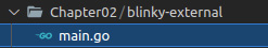
Figure 2.3 - Project structure for writing the code
We import the machine and time packages and put the following code into the main function:
- Declare and initialize a variable named
outputConfigwith a newPinConfigin output mode:outputConfig := machine.PinConfig{Mode: machine. PinOutput} - Declare and initialize a variable named
greenLEDwith a value ofmachine.D13:greenLED := machine.D13
- Configure the LED with the
outputConfiginstance we created earlier, by passing it as a parameter into theConfigurefunction:redLED.Configure(outputConfig)
- We then loop endlessly:
for { - Set
redLEDtoLow(off):redLED.Low()
- Sleep for half a second. Without sleeping, the LED would be turned on and off at an extremely high rate, so we sleep after each change in a state:
time.Sleep(500 * time.Millisecond)
- Set the
redLEDtoHigh(on):redLED.High()
- Sleep for half a second:
  time.Sleep(500 * time.Millisecond)
}
- Now flash the program using the
tinygo flashcommand using the following command:tinygo flash –target=arduino Chapter02/blinky-external/main.go
When the flash progress completes and the Arduino restarts, the red LED should blink at intervals of 500 ms.
Congratulations, you have just built your first circuit and written your first program to control external hardware! As we now know how to connect and control external LEDs on a breadboard, we can continue to build a more advanced circuit. Let's do just that in the next section.