Reader small image

You're reading from  Building a Home Security System with Raspberry Pi

Product typeBook
Published inDec 2015
Publisher
ISBN-139781782175278
Edition1st Edition
Right arrow
Author (1)
Matthew Poole
Matthew Poole
author image
Matthew Poole

Matthew Poole is a systems engineer based near Southampton on the south coast of England, with over 20 years of industry experience. After graduating in electronics and communications engineering, he went on to train as and become an air traffic engineer for Civil Aviation Authority, UK, working on microprocessor-based control and communications systems. Later, he became a software architect and mobile technology specialist, working for several consultancies and global organizations in both hands-on architecture and product-management roles . He is now a partner at Connecting Objects, a boutique systems consultancy focusing on the design of Bluetooth and other wireless-based IoT systems, taking ideas from concept to prototype. He is also the Director of Technology for Mobile Onboard, a leading UK-based transport technology company specializing in bus connectivity and mobile ticketing systems. He is also the author of Building a Home Security System with Raspberry Pi, Packt Publishing. You can find his blog at http://cubiksoundz.com and LinkedIn profile at https://www.linkedin.com/in/cubik, or you can reach him on Twitter at @cubiksoundz.
Read more about Matthew Poole

Right arrow

Chapter 2. Connecting Things to Your Pi with GPIO

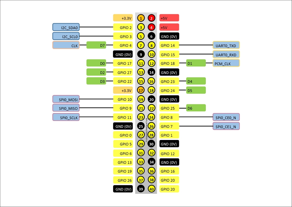
The Raspberry Pi has lots of ways to connect things to it, such as plugging things into the USB ports, connecting devices to the on-board camera and display ports, and connecting things to the various interfaces that make up the GPIO connector. As part of our home security project, we'll be focusing mainly on connecting things to the GPIO connector.

In this chapter, we will cover the following topics:

  • Examining the GPIO connector and what each of the pins does

  • Learning about the I2C and SPI buses that will be used in later chapters

  • Connecting an LED and a switch safely to the data pins, and accessing these data pins using simple scripts

  • Understanding the USB ports and their limitations

Prerequisites


Along with your Raspberry Pi, you'll need the following parts for the projects in this chapter:

  • A breadboard

  • An LED

  • A 220 ohm resistor (red, red, black)

  • A 10K ohm resistor (brown, black, orange)

  • A pushbutton or toggle switch

  • A hook-up wire:

    Our little collection of parts

Say hello to the GPIO


The GPIO connector is the large group of pins on the edge of your Raspberry Pi board. On earlier models, there were 26 pins that made up this connector. But, ever since the Model B+, there have been 40 pins, although the first 26 pins are identical to the previous models, and it's these 26 pins we'll be working with. You won't need to worry about the rest of the pins.

Essentially, the GPIO connector provides access to following:

  • Power supplies

  • Digital I/O pins

  • I2C bus

  • SPI bus

  • UART Serial bus

Some of the pins on the GPIO have more than one purpose, depending on how they are programmed. The following diagram is a reference guide to all of the pins on the GPIO. The GPIO numbers on the yellow labels relate directly to those on the Broadcom chip, and are numbers generally used within the scripts.

Digital I/O pins

The GPIO has 8 digital input/output pins available for use. These can be used to switch things on and off (in output mode), and also to detect when external things are switched...

Getting acquainted with the GPIO


Before we embark on connecting lots of things to our Pi board, it might be a good idea to just get acquainted with the GPIO through a couple of simple projects that will help us understand how to interact with the digital I/O pins using shell scripts.

Let there be light

This simple little project shows how to connect a GPIO output to an LED, and switch it on and off using shell commands.

The following diagram shows how to connect up the circuit using a breadboard:

Note

The pretty diagram that you just saw was produced using a free software tool from fritzing, which is an open-source hardware initiative to make electronics accessible as creative material for anyone. Download it from fritzing.org.

The LED anode (the positive side) is connected to the D0 digital I/O (pin 11 of the connector or GPIO17). When this pin is switched on, it will provide a 3.3V supply to the LED.

The LED is connected to the Ground pin via a 220R resistor on the cathode (negative side). The...

The most elaborate light switch in the world


By combining the two little projects earlier, we can now create a system that will do something useful when the pushbutton switch is pushed—for example, switching on the LED that we also have connected. Granted, we could just connect the LED directly to the switch and a battery, but not only would that be boring, it would defeat the point of what we're trying to do, which is programmatically sensing and controlling things.

Here's the breadboard layout for our elaborate light switch:

And here's the circuit diagram:

The illuminating script

Our full Bash script for our elaborate light switch is demonstrated next. This will loop endlessly, detecting the state of the switch GPIO pin, and will turn on the LED GPIO pin when the switch is pushed.

The code listing for light-switch.sh is as follows:

#!/bin/bash

#set up the LED GPIO pin
sudo echo 17 > /sys/class/gpio/export
sudo echo out > /sys/class/gpio/gpio17/direction

#set up the switch GPIO pin
sudo...

Summary


In this chapter, we introduced various ways to connect your Raspberry Pi to the outside world by looking at the various interfaces available on the GPIO. We've understood how to connect things to the digital pins on your Raspberry Pi's GPIO connector, and control and read them using simple Bash scripts. In particular, we've safely and properly connected a switch to a digital input pin, which will form the foundation for our home security detection circuits.

In the next chapter, we'll look at ways to expand the number of things we can connect to our Raspberry Pi, overcoming the limitation of having just the 8 digital pins available to us on the GPIO by tapping into other interfaces on the GPIO and building our own input/output expansion board.

lock icon
The rest of the chapter is locked
You have been reading a chapter from
Building a Home Security System with Raspberry Pi
Published in: Dec 2015Publisher: ISBN-13: 9781782175278
Register for a free Packt account to unlock a world of extra content!
A free Packt account unlocks extra newsletters, articles, discounted offers, and much more. Start advancing your knowledge today.
undefined
Unlock this book and the full library FREE for 7 days
Get unlimited access to 7000+ expert-authored eBooks and videos courses covering every tech area you can think of
Renews at $15.99/month. Cancel anytime

Author (1)

author image
Matthew Poole

Matthew Poole is a systems engineer based near Southampton on the south coast of England, with over 20 years of industry experience. After graduating in electronics and communications engineering, he went on to train as and become an air traffic engineer for Civil Aviation Authority, UK, working on microprocessor-based control and communications systems. Later, he became a software architect and mobile technology specialist, working for several consultancies and global organizations in both hands-on architecture and product-management roles . He is now a partner at Connecting Objects, a boutique systems consultancy focusing on the design of Bluetooth and other wireless-based IoT systems, taking ideas from concept to prototype. He is also the Director of Technology for Mobile Onboard, a leading UK-based transport technology company specializing in bus connectivity and mobile ticketing systems. He is also the author of Building a Home Security System with Raspberry Pi, Packt Publishing. You can find his blog at http://cubiksoundz.com and LinkedIn profile at https://www.linkedin.com/in/cubik, or you can reach him on Twitter at @cubiksoundz.
Read more about Matthew Poole