


In this chapter, we will explore LEDs with the Arduino. The fastest way to get some feedback from a system or from the Arduino is via an LED. They are simple devices which are either on or off. However, they form the basis for advanced technologies such as LED TVs, projectors, or lasers. In this chapter, we will also see how to use them efficiently and explore some interesting applications for them.
LED stands for Light Emitting Diode and, in its core, it's just a diode that emits light. LEDs are incredibly common these days and can be found at any common electronics shop. Radioshack, Digikey, Farnell, Sparkfun, Adafruit, or Pololu are just a few places we can buy LEDs from, online.
It is easy to make the LED blink on an Arduino. We turn it on, wait, turn it off, wait again, and then we repeat the cycle. However, this wait state will completely halt the Arduino execution. We want to make the LED blink while the Arduino is performing other actions.
The following code will make the internal LED blink on the Arduino without ever using the delay() function:
// Variable for keeping the previous LED state
int previousLEDstate = LOW;

unsigned long lastTime = 0; // Last time the LED changed state
int interval = 200; // interval between the blinks in milliseconds

void setup() {
  // Declare the pin for the LED as Output
  pinMode(LED_BUILTIN, OUTPUT);
}

void loop(){

  // Here we can write any code we want to execute continuously
  // Read the current time
  unsigned long currentTime = millis();

  // Compare the current time with the...
Luckily, the Arduino boards come with an internal LED connected to pin 13. It is simple to use and always there. But most times we want our own LEDs in different places of our system. We might connect something on top of the Arduino board and can no longer see the internal LED. Here, we will explore how to connect an external LED.
For this recipe, we need the following ingredients:
An Arduino board connected to the computer via USB
A breadboard and jumper wires
A regular LED (the typical LED size is 3 mm)
A resistor between 220–1,000 ohm
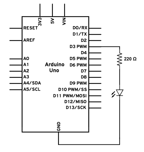
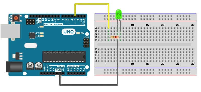
Follow these steps to connect an external LED to an Arduino board:
Mount the resistor on the breadboard. Connect one end of the resistor to a digital pin on the Arduino board using a jumper wire.
Mount the LED on the breadboard. Connect the anode (+) pin of the LED to the available pin on the resistor. We can determine the anode on the LED in two ways. Usually, the longer pin is the anode. Another way is to look...
The LED has two states: ON and OFF. But what if we want to adjust the brightness? How can we do that if we can only turn it ON or OFF? By turning it ON and OFF quickly.
We will use a technique called Pulse Width Modulation (PWM), which is built into the Arduino. It allows us to dim the LED with up to 256 settings.
We require the following ingredients for this recipe:
An Arduino board connected to the computer via USB
A breadboard and jumper wires
A regular LED
A resistor between 220–1,000 ohm
This recipe uses the same circuit as the Connecting an external LED recipe with a single difference, the pin used to connect the LED is not digital pin 2 but PWM pin 3.
We can get LEDs in a variety of colors these days, but what about an LED that can change color? We all know that a combination of Red, Green, and Blue (RGB) can give us any color. Using the Arduino PWM functionality, we will see how we can obtain 16 million color combinations with an RGB LED.
RGB LED stands for Red Green Blue LED. Inside such an LED we can find one red, one green, and one blue LED, mounted together.
The following are the ingredients needed for this recipe:
An Arduino board connected to the computer via USB
A breadboard and jumper wires
An RGB LED
Three equal resistors between 220–1,000 ohm
Follow these steps in order to connect an RGB LED to an Arduino board:

We all hate progress bars! They are always delaying us from doing something. But in the Arduino world they can be very handy. Here, we will see how to build one with LEDs. An LED bar graph is just a bunch of LEDs put together in a fancy case, but there are many uses for it. We can display the date from a sensor, show a critical condition, or make a funny light show with it.
We will need the following ingredients to execute this recipe:
An Arduino board connected to the computer via USB
A breadboard and jumper wires
An LED bar graph
Resistors between 220–1,000 ohm
Following are the steps to connect a 10-segment bar graph to the Arduino:
Mount the LED bar graph onto the breadboard.
If the bar graph is a common anode (+) configuration, connect the common anode (+) pin to the 5V port on the Arduino. If the bar graph is a common cathode (-), connect the pin to the GND port on the Arduino.
Connect each individual segment pin to one individual Arduino digital pin...
Since the beginning of electronics, 7-segment displays have been used to display numbers. They are easy to connect and understand, and quite fun to use once they are properly implemented. We can use such a display to show the status of our system or to show data from a sensor.
The following ingredients are needed for this recipe:
An Arduino board connected to the computer via USB
A breadboard and jumper wires
A 7-segment display
Resistors between 220–1,000 ohm
Follow these steps in order to connect a 7-segment display to the Arduino:
Mount the 7-segment display on the breadboard.
If the display is a common anode (+) configuration, connect the common anode (+) pin to the VCC port on the Arduino. If it is a common cathode (-), connect the cathode to the GND port on the Arduino.
Connect each individual segment pin to one individual Arduino digital pin using a resistor.