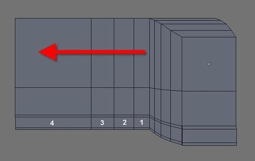
With the first part of the modeling created, we can now work on the wing modeling. The wing will be created from a series of extrusions coming from the side of the model, and the edges that we must select are pointed out in the following image:

Set the view to top and start a series of extrusions to create the mesh required for the wing. Four new extrusions will be needed.
With the base for the wing created, we will move a few vertices to shape the wing. Change the work mode to vertex, and move the vertices pointed out in the following image:

Those vertices were moved down in the Y axis.
Rotate the view to select the edges pointed out in the following image, and move them up in the Z axis. It will simulate a turbine air entry.