Reader small image

You're reading from  Raspberry Pi Essentials

Product typeBook
Published inApr 2015
Publisher
ISBN-139781784396398
Edition1st Edition
Right arrow
Author (1)
Jack Creasey
Jack Creasey
author image
Jack Creasey

Jack Creasey has been in the technology industry for more than 30 years, the last 15 years as a Senior Program Manager in hardware and software design. His expertise includes designing, developing, and teaching IT courseware. He is an avid inventor and holds 13 patents in hardware and software design. After retiring early from the computing industry, Jack avidly participates in social network groups that share his passion for next generation technology solutions.
Read more about Jack Creasey

Right arrow

Chapter 5. Port Input and Output on the Raspberry Pi

Digital input and output (I/O) is at the point where computer programming touches the real world. The Raspberry Pi has a rich I/O structure that includes 3.3 Volts, input and output interface ports, Serial Peripheral Interface (SPI), and Inter-Integrated Circuit (I2C). Using this I/O structure, you will drive LEDs as output indicators and then use the Tkinter interface to sense switches as input.

After completing this chapter, you will be able to:

  • Understand the Raspberry Pi digital I/O port configuration

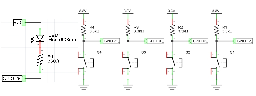
  • Drive LEDs and sense actuation of switches

  • Add a switch interface to the Internet radio project

Understanding Raspberry Pi digital input and output ports


The Broadcom SOC (BCM2835 and BCM2836 in the Raspberry Pi Model 2-B) used to implement the Raspberry Pi is a CMOS device, and the I/O ports are driven by 3.3V logic gates. When connecting direct internal functionality such as digital I/O ports to the outside world or exposing them to the outside world via external wiring, there are risks involved. A single digital port might be programmatically configured to be an input or an output, and with a pull-up or pull-down termination. The ports are directly connected to the Pi SOC computer chip. These ports are static and load sensitive; the wrong load types and high voltages could potentially damage the CPU.

The following image shows a typical I/O port configuration for the digital I/O ports on this type of SOC. While there is an output-enable to turn on the port driver, the input buffer can always detect the logic level of the GPIO pin. Note that, in this typical implementation, there are...

Driving LEDs as output indicators


LED indicators can take many forms, from a single LED indicator through to complex LED X-Y arrays and digit displays. If you have multiple indicator LEDs, it is preferable to include an LED driver and even better to offload this to an I2C controller, which we will explain in Chapter 6, Driving I2CPeripherals on the Raspberry Pi. If you have just a few LEDs to drive and are short of output pins for each LED, you will want to read up on Charlieplexing as a way of reducing the port count required (http://en.wikipedia.org/wiki/Charlieplexing).

For our demo, we will use a single LED attached to a single GPIO port. We will attach it to the GPIO 26 port with a series resistor to limit the current through the device. This is what your breadboard should look like, along with the schematic:

When the GPIO pin number 26 is high, the LED is off, and when it is low, a current of approximately 4 mA flows from the 3.3V supply through the LED and into the GPIO pin to the ground...

TKinter LED demo


Now, let's explore a window-based interface with more examples of how to drive LEDs.

The code is divided into sections and includes a summary of the functionality for the major blocks but not all of the code. Review the code and the summaries following the image before you download the code from http://1drv.ms/1ysAxkl

In order for you to have a mental model of the LED demo as you read through the code, here is the TKinter interface (GPIO test) when rendered:

Block 1 – initialization

This block loads the required libraries, does initial setup, and defines the TKinter window. It is possible to set the window size here but, in this code, I simply allow the window size to be defined by the elements it contains:

#!/usr/bin/python3

from tkinter import *
from time import sleep
import RPi.GPIO as GPIO

GPIO.setmode(GPIO.BCM)
GPIO.setup(26, GPIO.OUT, pull_up_down=GPIO.PUD_UP, initial=1)

#Python variable
debug=True
tkrun=0
tkenable=0
out=0

#Define the TKinter window
root = Tk() #Makes...

TKinter switch demo


Since the action code for Python is so similar to that for TKinter, we will go directly to a TKinter interface for switch sensing. Since the plan is to eventually create push buttons for our Internet radio, let's show the breadboard schematic that we need to achieve this:

Note

Warning: While the schematic shown is quite OK for breadboard use, it is not suitable where the wires to the switches are long (greater than a few inches). Notice that the GPIO pin would be exposed directly to any fault conditions. It is advisable to put at least a 1k Ohm series resistor to the GPIO pin. Never run the 5 Volt or 3.3 Volt supply through a long line to the switch (or LED location) as this directly exposes the supply to any potential wiring faults.

In preparation for the demo, complete the following:

  1. Download the tkswitch21.py code from http://1drv.ms/1ysAxkl.

  2. Store the tkswitch21.py file in /home/pi/gpio.

  3. Run the code using IDLE3 by starting from a command line with sudo idle3 (remember...

Adding a physical switch interface to the Internet radio


Now that you have had the opportunity to experiment with sensing switches, we need to develop the code to add the external buttons to the Internet radio.

We will use four buttons, which are as follows:

  • Two buttons for scrolling forward and backwards through the playlist using the Spinbox actions

  • A button to select or start the playlist entry

  • A button to stop the radio

  • An LED to indicate each switch entry

  • The mouse interface will still work

The code for adding a switch interface is encapsulated enough to provide a small demo of the buttons in action using IDLE3 before we combine the code.

The complete demo code is shown after the following paragraph. You have the option to type it in and then save it in a file you created, called /home/pi/gpio/tkswitches.py. Or you can download the tkswitches.py code from http://1drv.ms/1ysAxkl.

The code opens an empty TKinter window when started and allows you to test all four buttons and the LED. The only...

Project 1 – Add a switch interface to the Internet radio


Now that we have seen the code to implement the external switch/LED actions and integrated that with a basic TKinter GUI, we can show the final result. The program is close to 300 lines long, but we hope that having incrementally added functionality, you can read through it with relative ease.

To start this project:

  • Download the swradio.py code file from http://1drv.ms/1ysAxkl.

  • Save the file in /home/pi/radio/bin.

  • You can run the program swradio.py in IDLE3 to see the console output, but remember to use a command prompt to start IDLE3 as the root (sudo idle3). The window interface still works but, in addition, you can now use the buttons to navigate, start, and stop the stations.

There are many workarounds for setting permissions and groups to give root access required for the RPi.GPIO; however, the following set of instructions simply start the application (swradio.py) using a root instance of Python 3 when the desktop starts.

To set up...

Summary


Now that we've completed the fifth chapter, let's review some of the main tasks you learned how to do:

  • Driving LEDs and sensing switches using digital I/O ports and unearthing the potential problems and restrictions that apply to their use

  • Adding a switch interface with an activity indicator LED to the Internet radio project from Chapter 4, Raspberry Pi Audio Input and Output

In the next chapter, you will start to exercise some of the Raspberry Pi input and output ports to drive RC-servos over the I2C (SMBUS) interface.

lock icon
The rest of the chapter is locked
You have been reading a chapter from
Raspberry Pi Essentials
Published in: Apr 2015Publisher: ISBN-13: 9781784396398
Register for a free Packt account to unlock a world of extra content!
A free Packt account unlocks extra newsletters, articles, discounted offers, and much more. Start advancing your knowledge today.
undefined
Unlock this book and the full library FREE for 7 days
Get unlimited access to 7000+ expert-authored eBooks and videos courses covering every tech area you can think of
Renews at $15.99/month. Cancel anytime

Author (1)

author image
Jack Creasey

Jack Creasey has been in the technology industry for more than 30 years, the last 15 years as a Senior Program Manager in hardware and software design. His expertise includes designing, developing, and teaching IT courseware. He is an avid inventor and holds 13 patents in hardware and software design. After retiring early from the computing industry, Jack avidly participates in social network groups that share his passion for next generation technology solutions.
Read more about Jack Creasey