

In this chapter, we are going to have some fun, and apply all that we saw so far in the book to simple, entertaining, but also useful IoT projects that use Arduino. In these examples, we are going to build a clock that gets the time from the cloud, and also an actual GPS tracker that will display the position of your Arduino project on Google Maps!
As the first project of this chapter, we are going to build a simple clock that gets the time from a cloud server, using Arduino. The time itself will actually be displayed on an OLED screen, also controlled by the Arduino board.
For this project, you will need an OLED screen to display the time that can be controlled via Arduino. I recommend using the 128x64 OLED screen from Adafruit (https://www.adafruit.com/products/938).
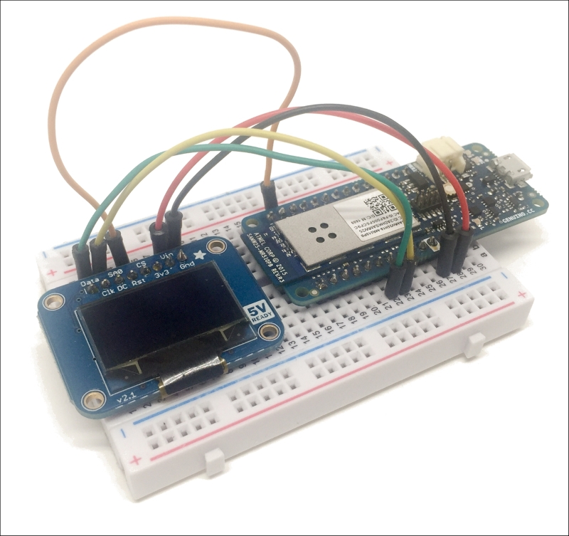
We can now assemble the project, which basically consists of simply connecting the Arduino board to the OLED screen. First, place both boards on a breadboard. Then, connect the VIN pin of the OLED board to the VCC of the Arduino board, and GND to GND. After that, connect the data and clock pins: data goes to the SDA of the Arduino board, and CLK goes to the SCL of the Arduino board. Finally, connect the RST pin of the OLED screen to pin 4 of the Arduino board.
This is the final result:
In this recipe, we are going to learn how to make a digital version of a candle using Arduino. We'll see how to control a multicolor LED to emulate the behavior of a real candle. It's just the perfect project for Valentine's Day, Christmas, and other celebrations.
For this project, the only thing you will need is an Adafruit NeoPixel, which is a smart RGB LED that can be easily controlled via Arduino.
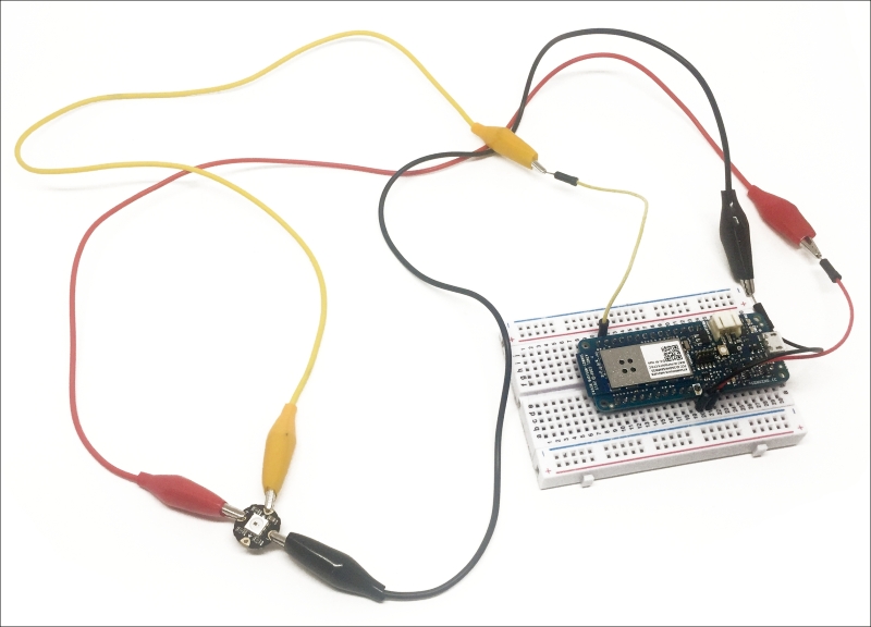
I also used some alligator clips to connect the Arduino board to the NeoPixel.
Assembling the project is really easy – you just need to connect the NeoPixel input pin to Arduino pin 5, GND to GND, and VCC to VCC of the Arduino board.
This is the final result:
On the software side, the only thing you need is to install the Adafruit_NeoPixel library, which you can install from the Arduino library manager.
In the previous recipe, we learned how to build a digital candle using Arduino. But what about the IoT aspect of the project? Well, this is what we are going to deal with in this recipe. We are going to connect the project from the previous recipe to the cloud, and learn how to control it from anywhere. This could, for example, be a candle that you send to loved ones that are far away, and that you suddenly switch on to show you are thinking about them.
For this project, first you need to follow the previous recipe to build the candle. Then, you can configure the candle with some new code to control it from the cloud.
You will need to install the PubSubClient and aREST libraries, which you can easily do by using the Arduino library manager.
The sketch starts as always with the required libraries:
#include <SPI.h>
#include <WiFi101.h>
#include <PubSubClient.h>
#include <aREST.h>
#include <Adafruit_NeoPixel.h>
#define...
Bitcoin is currently the most used cryptocurrency in the world. There are a lot of Bitcoin tickers (plugins or websites that indicate the current price of Bitcoin) out there, but wouldn't it be cool if you could have your own little Bitcoin ticker on your desk? This is exactly what we are going to do in this recipe.
For the hardware, you can refer to the very first recipe of this chapter, as it uses exactly the same hardware that we use in this project: an OLED screen connected to the Arduino MKR1000 board.
Let's now see how to configure the project. As the sketch is quite long, I will only highlight the most important parts here. First, we define the Wi-Fi credentials, and we also define the API that we'll use to grab the current price of Bitcoin:
// WiFi settings
const char* ssid     = "Jarex_5A';
const char* password = "connect1337';

// API server
const char* host = "api.coindesk.com';
Then, in the loop() function of the sketch, we create...
In this recipe, we are going to learn how to completely assemble a GPS module with Arduino, and make sure that it is working. The goal is to build a GPS tracking module with Arduino, which is what we will see in the next recipe.
For this project, we will have to use an Arduino Uno board, instead of the usual MKR1000 board, as at the time of writing, the GPS/GSM module I used was not compatible with the MKR1000 board. This is the list of all the components that you will need for this recipe:
Arduino Uno (https://www.sparkfun.com/products/11021)
Adafruit Fona 808 breakout (http://www.adafruit.com/product/2542)
GSM uFL antenna (http://www.adafruit.com/products/1991)
GSM SIM card with GPRS data available
3.7V LiPo battery (http://www.adafruit.com/products/328)
LiPo battery charger (http://www.adafruit.com/products/1904)
Passive GPS antenna (https://www.adafruit.com/product/2461)
Breadboard (https://www.sparkfun.com/products/12002)
Jumper wires (https://www.sparkfun...
In the last recipe of this chapter, we are going to build a simple GPS tracker using the hardware we built in the previous recipe. We will send the current GPS location of the project to a cloud server, and then use this to display the position of the project in real time on a Google Maps widget.
You will, of course, need to have built the hardware in the previous recipe, and make sure that the GPS is working correctly. If that's not done yet, please refer to the previous recipe.
Let's now see how to configure the project so that it sends data to Dweet.io, which is a cloud server we already used in this book. As the code is quite long, I will only highlight the most important parts here.
First, let's define a new thing called gps_tracker:
String dweetThing = "gps_tracker';
Inside the loop() function of the sketch, we create a new request to Dweet.io, by including the latitude, longitude, and battery level inside the request:
uint16_t statuscode;
  int16_t...
In this part of the chapter, we are going to see what can go wrong when configuring your board and connecting it to the Internet. Indeed, some of the steps involved here are quite complex and many things can go differently than expected.
The first thing that can happen is that the OLED module has not been correctly connected to the Arduino board. For example, you could have mixed the SCL and SDA pins. Also make sure that you have correctly connected the reset pin. Then, make sure that the Wi-Fi credentials have been correctly entered in the sketch.
The GPS module that I used in this chapter really needs to have a clear line of sight with the sky to work correctly, unlike the more advanced modules that you have in your phone, for example. So if the project doesn't work, make sure the module is close to a window or even slightly outside. Also make sure that you have connected...