

In this chapter, after a brief introduction and a short note on installation, we will go over the most widely used pallets and objects Icon toolbar from a standard installation of LabVIEW and provide a brief explanation of what each object does. We will end the chapter with an example of a LabVIEW program generally called a Virtual Instrument (VI).

LabVIEW is a graphical developing and testing environment unlike any other test and development tool available in the industry. LabVIEW sets itself apart from traditional programming environments by its completely graphical approach to programming. As an example, while representation of a while loop in a text-based language such as C consists of several predefined, extremely compact, and sometimes extremely cryptic lines of text, a while loop in LabVIEW is actually a graphical loop. The environment is extremely intuitive and powerful, which makes for a short learning curve for the beginner. LabVIEW is based on what is called the G language, but there are still other languages, especially C, under the hood. However, the ease of use and power of LabVIEW is somewhat deceiving to a novice user. Many people have attempted to start projects in LabVIEW only because, at first glance, the graphical nature of the interface and the concept of drag and drop used in LabVIEW appears to do away with the required basics of programming concepts and classical education in programming science and engineering. This is far from the reality of using LabVIEW as the predominant development environment. While it is true that, in many higher-level development and testing environments, especially when using complicated test equipment and complex mathematical calculations or even creating embedded software, LabVIEW's approach will be a much more time-efficient and bug-free environment which otherwise would require several lines of code in a traditional text based programming environment, one must be aware of LabVIEW's strengths and possible weaknesses.
LabVIEW does not completely replace the need for traditional text based languages and, depending on the entire nature of a project, LabVIEW or another traditional text based language such as C may be the most suitable programming or test environment.
Installation of LabVIEW is very simple and it is just as routine as any modern-day program installation; that is, insert the DVD 1 and follow the onscreen guided installation steps.
LabVIEW comes in one DVD for the Mac and Linux versions but in four or more DVDs for the Windows edition (depending on additional software, different licensing, and additional libraries and packages purchased). In this book, we will use the LabVIEW 2013 Professional Development version for Windows. Given the target audience of this book, we assume the user is fully capable of installing the program. Installation is also well documented by National Instruments (NI) and the mandatory 1-year support purchase with each copy of LabVIEW is a valuable source of live and e-mail help. Also, the NI website (www.ni.com) has many user support groups that are also a great source of support, example codes, discussion groups, local group events and meetings of fellow LabVIEW developers, and so on.
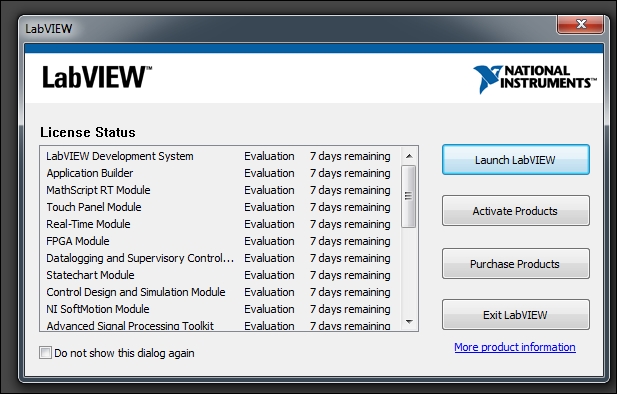
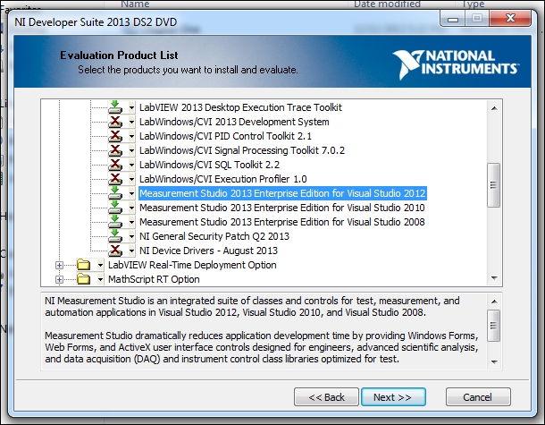
It's worth noting for those who are new to the installation of LabVIEW that the installation DVDs include much more than what an average user would need and pay for. We do strongly suggest that you install additional software (beyond what has been purchased and licensed or immediately needed!). This additional software is fully functional in demo mode for 7 days, which may be extended for about a month with online registration. This is a very good opportunity to have hands-on experience with even more of the power and functionality that LabVIEW is capable of offering. The additional information gained by installing the other software available on the DVDs may help in further development of a given project. Just imagine, if the current development of a robot only encompasses mechanical movements and sensors today, optical recognition is probably going to follow sooner than one may think. If data acquisition using expensive hardware and software may be possible in one location, the need for web sharing and remote control of the setup is just around the corner. It is very helpful to at least be aware of what packages are currently available and be able to install and test them prior to a full purchase and implementation. The following screenshot shows what may be installed if almost all the software on all the DVDs is selected:
When installing a fresh version of LabVIEW, if you do decide to observe the given advice, make sure to click on the + sign next to each package you decide to install and prevent any installation of LabWindows/CVI... and Measurement Studio... for Visual Studio. LabWindows, according to NI, is an ANSI C integrated development environment. Also note that, by default, NI device drivers are not selected to be installed. Device drivers are an essential part of any data acquisition and appropriate drivers for communications and instrument(s) control must be installed before LabVIEW can interact with external equipment. Also, note that device drivers (on Windows installations) come on a separate DVD, which means that one does not have to install device drivers at the same time that the main application and other modules are installed; they can be installed at any time later on. Almost all well-established vendors are packaging their product with LabVIEW drivers and example codes. If a driver is not readily available, NI has programmers that would do just that. But this would come at a cost to the user.
VI Package Manager, now installed as a part of standard installation, is also a must these days. NI distributes third-party software and drivers and public domain packages via VI Package Manager. We are going to use examples using Arduino (http://www.arduino.cc) microcontrollers in later chapters of this book. Appropriate software and drivers for these microcontrollers are installed via VI Package Manager. You can install many public domain packages that further install many useful LabVIEW toolkits to a LabVIEW installation and can be used just as those that are delivered professionally by NI.
Finally, note that the more modules, packages, and software that are selected to be installed, the longer it will take to complete the installation. This may sound like making an obvious point but, surprisingly enough, installation of all software on the three DVDs (for Windows) takes up over 5 hours! On a standard laptop or PC we used. Obviously, a more powerful PC (such as one with a solid state hard drive) may not take such long time.
Once the LabVIEW application is launched, by default two blank windows open simultaneously-a Front Panel and a Block Diagram window-and a VI is created:
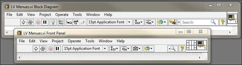
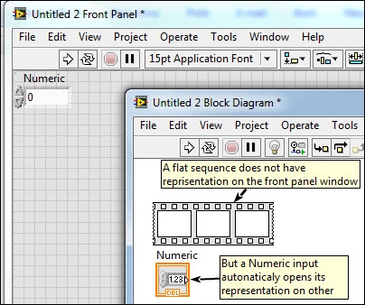
VIs are the heart and soul of LabVIEW. They are what separate LabVIEW from all other text-based development environments. In LabVIEW, everything is an object which is represented graphically. A VI may only consist of a few objects or hundreds of objects embedded in many subVIs. These graphical representations of a thing, be it a simple while loop, a complex mathematical concept such as Polynomial Interpolation, or simply a Boolean constant, are all graphically represented. To use an object, right-click inside the Block Diagram or Front Panel window, a pallet list appears. Follow the arrow and pick an object from the list of objects from subsequent pallet and place it on the appropriate window. The selected object can now be dragged and placed on different locations on the appropriate window and is ready to be wired. Depending on what kind of object is selected, a graphical representation of the object appears on both windows. Of course, there are many exceptions to this rule. For example, a while loop can only be selected in Block Diagram and, by itself, a while loop does not have a graphical representation on the Front Panel window. Needless to say, LabVIEW also has keyboard combinations that expedite selecting and placing any given toolkit objects onto the appropriate window:
Each object has one (or several) wire connections going into it as input(s) and coming out as its output(s). A VI becomes functional when a minimum number of wires are appropriately connected to the input and output of one or more objects. Later, we will use an example to illustrate how a basic LabVIEW VI is created and executed.
A few words about menu bar icons are necessary. Note that actual menus and submenus do the main work and one must be familiarized with the functionality of many menus and their subsequent submenus and panels. The following are the absolutely necessary items a user must be familiar with to begin work in LabVIEW.

The Run button will commence execution of a VI given that a minimum of code is provided at least in the Block Diagram window. A few points must be noted:
A program may have enough code and this button may be pressed but there may not be anything obvious or present in any of the open windows
A program or a VI may run perfectly fine and extremely fast, as fast as the speed of the computer that LabVIEW is running on (given all operating system delays, background programs and processes, and so on) without anything noticeable to the human eye. Care must be taken to spot insert alerts, delays, or indicators if needs be.

When a program is successfully running (independent of the actual intended objective of the VI) these four Icons change shape from their idle state appearance. Note that there may be unintentional loops that will appear as "successful running program to LabVIEW" such as a
whileloop that does not have correct exit condition(s), typically called an endless loop. In such a case (where even milliseconds of delay is not implemented), LabVIEW would get hold of all processors on the computer and may lock the computer such that no buttons on LabVIEW or, for that matter, even keyboard and mouse clicks would be effective. In these cases, depending on the operating system in use, a user may have to temporarily shut down the computer to be able to escape from the locked-up situation. LabVIEW precompiles as objects are placed on the programming windows; this is an important fact that a user must keep in mind and although it is an obvious benefit, it may unintentionally work against the user if proper care is not taken while designing and implementing a project.

The broken link error changes the shape of the Run button. The Run button will change shape to this form if:
Not enough inputs and/or outputs are correctly wired
There are connections errors
An unwired object is placed in any of the two main windows of a VI

The Run continuously state is shown as follows.

The Run continuously (active) button (two looping arrows) will execute a VI over and over even though the actual VI logic has not provisioned to run more than once. Used with caution, this button is a good way of running/testing a code segment (such as a subVI) which may be planned to be incorporated in a looped project.

The Stop button.

The Pause button.

The highlight execution button may be the quickest and the most useful way of debugging or simply viewing the actual sequence of execution of each object and the value carried by a wire or output of a function. When evoked prior to clicking the Run button, LabVIEW slows down the execution of program such that a moving dot, and most likely several moving dots on different wires, on the currently executing wire is traceable by human eye and speed.

Debug tools, start single stepping(s) and step out.
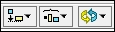
Arrange tools. LabVIEW is graphical programming environment (although scripts may be used inside a few functions) and, as such, proper arranging of graphical representation of each object is essential to a readable and manageable source code. These buttons are very helpful in arranging and aligning groups of objects.

There are many occasions that an object must move to the back or to the front of a layered segment; the Reorder button arranges buttons with respect to layers rather than the position of an object in a given layer. Mostly used in the decorative aspect of a Front Panel window.

Any VI is created by manually placing an object onto its respective window and probably resizing it (such as a
forloop or awhileloop) and all objects need to be manually wired. Even on a simple VI, this process may get overwhelmingly complicated and it is very hard to trace each wire from where it starts to where it ends. Clean Up can actually help to automatically rearrange a complete VI or a selected segment of the code. However, save the code before applying automatic Clean Up to your code since there exist situations where a Clean Up may make the Block Diagram prettier but may also cause the code to be harder to read and/or add or remove any of its objects. With little experience and continuous and periodic applications of Clean Up, this could become a very useful tool.

Activating the Help button and hovering over any object will automatically open a window with very helpful information about that object, related documents, and even links to examples and usage information.

The Connector pane icon object is used to connect wires to input of this subVI and/or have access to its output(s) if either case does exist.

Icon editing tool, by default, any new VI has this icon and only the subsequent numbers on the bottom right of the icon are enumerated. By clicking on this tool, an Icon editor subprogram is launched where users can create and edit their own icons or import previously created icons.

When a VI is created, the actual file is represented by this icon, which can also be modified by an editor.
This is a fairly simple program with simple user interaction. Once the program has been launched, it uses a while loop to wait for the user input. This is a typical behavior of almost any user-friendly program. For example, if the user launches Microsoft Office, the program launches and waits for the user to pick a menu item, click on a button, or perform any other action that the program may provide. Similarly, this program starts execution but waits in a loop for the user to choose a command. In this case only a simple Start or Stop is available. If the Start button is clicked, the program uses a for loop function to simply count from 0 to 10 in intervals of 200 milliseconds. After each count is completed, the gauge on the Front Panel, the GUI part of the program, is updated to show the current count. The counter is then set to the zero location of the gauge and the program awaits subsequent user input. If the Start button is clicked again, this action is repeated, and, obviously, if the Stop button is clicked, the program exits. Although very simple, in this example, you can find many of the concepts that are often used in a much more elaborate program. Let's walk through the code and point out some of these concepts.
The following steps not only walk the reader through the example code but are also a brief tutorial on how to use LabVIEW, how to utilize each working window, and how to wire objects.
Launch LabVIEW and from the File menu, choose New VI and follow the steps:
Right-click on the Block Diagram window.
From Programming Functions, choose Structures and select While Loop.
Click (and hold) and drag the cursor to create a (resizable) rectangle.
On the bottom-left corner, right-click on the wire to the stop loop and choose Create a control. Note that a Stop button appears on both the Block Diagram and Front panel windows.
Inside the
whileloop box, right-click on the Block Diagram window and from Programming Function, choose Structures and select Case Structures. Click and (and hold) and drag the cursor to create a (resizable) rectangle.On the
Front Panelwindow, next to the Stop button created, right-click and from Modern Controls, choose Boolean and select an OK button. Double-click on the text label of the OK button and replace the OK button text withStart. Note that an OK button is also created on the Block Diagram window and the text label on that button also changed when you changed the text label on the Front Panel window.On the Front Panel window, drag-and-drop the newly created Start button next to the tiny green question mark on the left-hand side of the Case Structure box, outside of the case structure but inside the
whileloop. Wire the Start button to the Case Structure.Inside the Case Structure box, right-click on the Block Diagram window and from Programming Function, choose Structures and select For Loop. Click and (and hold) and drag the cursor to create a (resizable) rectangle.
Inside the Case Structure box, right-click on N on the top-left side of the Case Structure and choose Create Constant. An integer blue box with a value of 0 will be connected to the For Loop. This is the number of irritations the
forloop is going to have. Change0to11.Inside the For Loop box, right click on the Block Diagram widow and from Programming Function, choose Timing and select Wait(ms).
Right-click on the Wait function created in step 10 and connect a integer value of
200similar to step 9.On the Front Panel window, right-click and from Modern functions, choose Gauge. Note that a Gauge function will appear on the Block Diagram window too. If the function is not inside the For Loop, drag and drop it inside the For Loop.
Inside the For loop, on the Block Diagram widow, connect the iteration count
ito the Gauge.On the Block Diagram, right-click on the Gauge, and under the Create submenu, choose Local variable.
If it is not already inside the
whileloop, drag and drop it inside thewhileloop but outside of the case structure.Right-click on the local variable created in step 15 and connect a Zero to the input of the local variable.
Click on the Clean Up icon on the main menu bar on the Block Diagram window and drag and move items on the Front Panel window so that both windows look similar to the following screenshots:

When LabVIEW is launched, a default screen such as in the following screenshot appears on the screen:
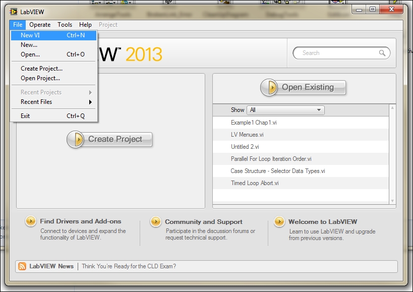
The most common way of using LabVIEW, at least in the beginning of a small project or test program, is to create a new VI. A common rule of programming is that each function, or in this case VI, should not be larger than a page. Keep in mind that, by nature, LabVIEW will have two windows to begin with and, being a graphical programming environment only, each VI may require more screen space than the similar text based development environment. To start off development and in order to set up all devices and connections required for tasks such as data acquisition, a developer may get the job done by simply creating one, and, more likely several VIs. Speaking from experience among engineers and other developers (in other words, in situations where R&D looms more heavily on the project than collecting raw data), quick VIs are more efficient initially, but almost all projects that start in this fashion end up growing very quickly and other people and other departments will need be involved and/or be fed the gathered data. In most cases, within a short time from the beginning of the project, technicians from the same department or related teams may be need to be trained to use the software in development. This is why it is best to develop the habit of creating a new project from the very beginning. Note the center button on the left-hand window in the preceding screenshot.
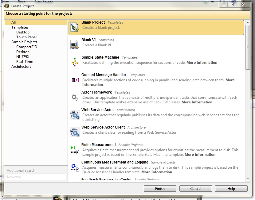
Creating a new project (as opposed to creating VIs and sub-VIs) has many advantages and it is a must if the program created will have to run as an executable on computers that do not have LabVIEW installed on them. Later versions of LabVIEW have streamlined the creation of a project and have added many templates and starting points to them.
Although, for the sake of simplicity, we created our first example with the creation of a simple VI, one could almost as easily create a project and choose from many starting points, templates, and other concepts (such as architecture) in LabVIEW.
The most useful starting point for a complete and user-friendly application for data acquisition would be a state machine. Throughout the book, we will create simple VIs as a quick and simple way to illustrate a point but, by the end of the book, we will collect all of the VIs, icons, drivers, and sub-VIs in one complete state machine, all collected in one complete project.
From the project created, we will create a standalone application that will not need the LabVIEW environment to execute, which could run on any computer that has LabVIEW runtime engine installed on it.
LabVIEW is a complete object-oriented development and test environment based on the G language. As such, it is a very powerful and complex environment. In this chapter, we went through an introduction to LabVIEW and the main functionality of each of its icons by way of an actual user-interactive example. Accompanied by appropriate hardware (both NI as well as many industry standard test, measurement, and development hardware products), LabVIEW is capable of covering developing embedded systems, fuzzy logic, and almost everything in between!
In this chapter, we covered the basics of LabVIEW, from installation to an in-depth explanation of each and every element in the toolbar.
In the next chapter, we will discuss the most common and practical ways we may connect the computer which LabVIEW is running on to the device(s) we need to collect data from.
You have been reading a chapter from
Data Acquisition Using LabVIEWPublished in: Dec 2016Publisher: PacktISBN-13: 9781782172161
Register for a free Packt account to unlock a world of extra content!
A free Packt account unlocks extra newsletters, articles, discounted offers, and much more. Start advancing your knowledge today.
undefined
Unlock this book and the full library FREE for 7 days
Get unlimited access to 7000+ expert-authored eBooks and videos courses covering every tech area you can think of
Renews at $15.99/month. Cancel anytime