


Testing CODESYS
Usually, the first program a person writes in a new language is called Hello, World!. It is a simple program that will display the words Hello and World on the screen. The PLC equivalent of this is turning a coil off and on. To get familiar with and test our CODESYS installation, we’re going to create that simple ladder logic program:
- Once CODESYS is installed, launch the program, and you should see a page on which you can create a new project. This page is called the Start page and it will have a New Project link.
- Click New Project and you should see a New Project window. Here, click Standard project, name the project
Chapter1, and then click OK. - Now, you should see a standard project box. This step is the step where you select the programming interface for the project. By default, it will be set to FBD. This will need to be changed to Ladder Logic Diagram. To do this, click the PLC_PRG drop-down box, select Ladder Logic Diagram (LD), and press OK.
- After the project is created, a file tree will appear in the device tab to the left of the screen. Double-click on PLC_PRG and you will see a ladder logic development screen.
Creating the program
The aforementioned steps will create a ladder logic project. The project that’s generated will have all the necessary files and dependencies you need to implement your code. As such, all you will need to focus on is implementing the program’s logic. The file that we are going to implement our logic in is labeled PLC_PRG.
The PLC_PRG file
This is the PLC_PRG file that serves as the main entry point for the PLC program:
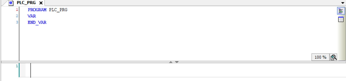
Figure 1.1 – PLC_PRG ladder logic development
This is the first file that will be called when a PLC program is run. This is the file in which we will develop our Hello, World! ladder logic program.
To break this area down, the bottom of Figure 1.1 is a rung. This is where the actual Ladder commands will go. Above that, in the text area, is where variables are declared. The ladder logic tools can be found to the right of the screen, as shown in Figure 1.2.
ToolBox
ToolBox is where all the ladder logic commands can be found for use in the rungs:
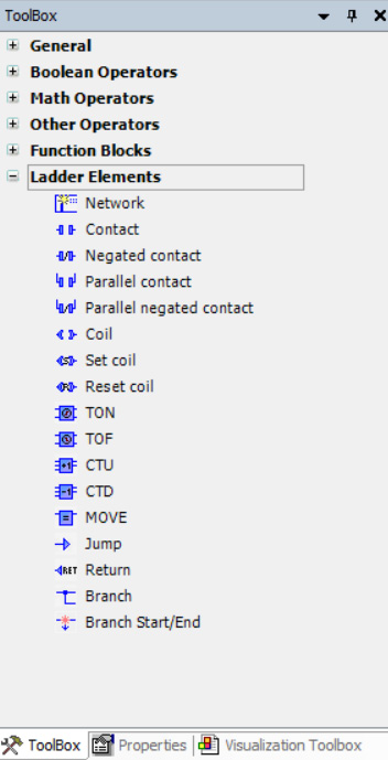
Figure 1.2 – Ladder logic ToolBox
As can be seen in Figure 1.2, there are many drop-down menus. The menus contain many different ladder logic instructions. For our purposes, click Ladder Elements. Once you expand that menu, drag over both a contact to the Start here box and a coil to the Add output or jump here box and insert the instructions in the rung area. Also, add two Boolean variables to the variable area (see the following format).
Variable code
This is the full code that is needed to declare all the variables needed for the program:
PROGRAM PLC_PRG
VAR
   input : BOOL;
   output: BOOL:
END_VAR
This code creates two Boolean variables called input and output. Assign the input variable to the contact and the output variable to the coil by clicking on ???, then click on the three dots and select the appropriate variable. The name of the variable can also be typed in directly in place of ???. The input variable will be used to change the state of the output variable. In short, the purpose of our Hello, World! program will be for the output variable to mirror the state of the input variable.
Completed Hello, World! project
When you are finished setting up your project, it should reflect what is in Figure 1.3:
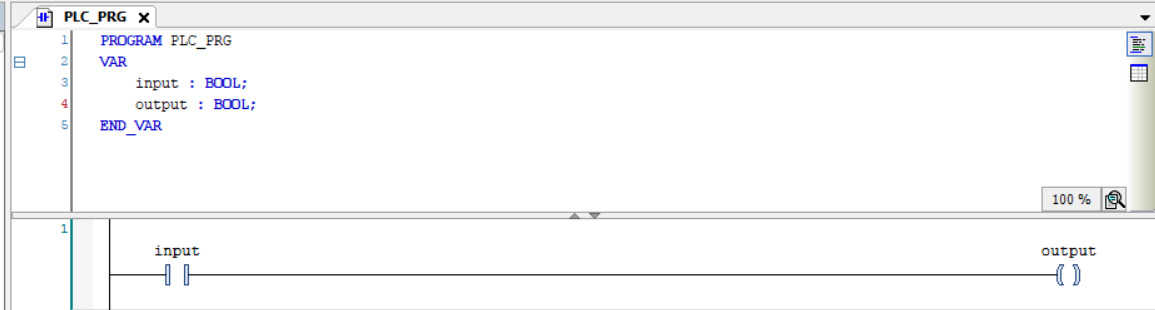
Figure 1.3 – Completed PLC Hello, World! program
Figure 1.3 is the code needed to run a Hello, World! program. Essentially, this code will turn the output variable on when the input variable is on, and off when the input variable is off.
To test the simulator to see the program work, click Online on the ribbon at the top of the screen and select Simulation. This will tell CODESYS that there is no physical hardware, and that you want to run the program virtually. Click the button that is shown in Figure 1.4.
Login button
This button is the Login button that will log you into the virtual hardware. When the button has been pressed, the icon next to it will enable:

Figure 1.4 – The login button
Login will activate the program; however, it may not always run the program. To run the program, you must press the Play button next to the grayed-out icon in Figure 1.4.
You should now have a development screen that resembles Figure 1.5.
A running ladder logic program
Figure 1.5 is the running PLC program with all of the variables in a FALSE or off state:
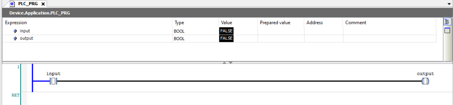
Figure 1.5 – Hello, World!
To turn the output variable on, you will need to change the false variable of the input variable to a true value. To do this, double-click the Prepared value field in the input row until it says TRUE. Once you have a blue box that says TRUE in the cell, right-click the cell and press Write All Values Of ‘Device. Application’. Once you do this, your program should resemble Figure 1.6.
Toggling input to true
This is the output when the input variable is set to TRUE:
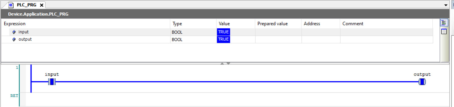
Figure 1.6 – Hello, World! with a TRUE input
When the input variable is set to TRUE, the whole line turns blue and the inner square in the output contact is also turned blue. This means that the rung is activated and is on. Essentially, when you see blue, that means that the rung is active and is doing whatever logic you have programmed in.
The input can also be toggled back to FALSE. The steps are the same for toggling the input variable to a FALSE state with the only exception being that you will set the prepared value to FALSE instead of TRUE.
Toggling input to false
This is the output when the input variable is set to FALSE:
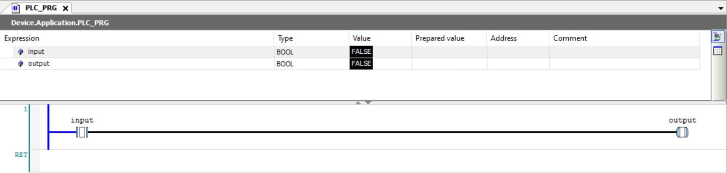
Figure 1.7 – Hello, World! with a FALSE input
As can be seen, setting the input variable to FALSE changes all the blue back to black. Blue meant the rung was running, and black means the rung is off.