It's rare that all the features of the part we want to design are in the same two-dimensional plane.
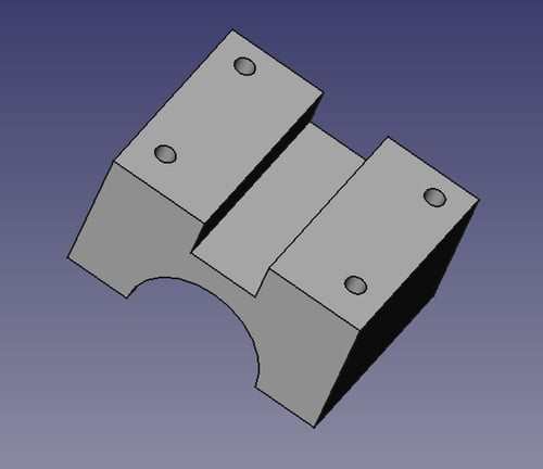
Imagine that we want to add holes to the top surface of the part we designed in the Modeling with constraints (Must know) recipe as shown in the following screenshot. To do this, we need a way to associate a new sketch with the top face of the part.
An external constraint gives us a way to relate elements of our sketch to entities that are not in the sketch itself, like the face of a part.
In this recipe we'll also show how features in a sketch can be related to an existing object.
Along the way, we'll also introduce construction lines and external constraints.
This recipe uses functionality from FreeCAD version 0.13 and later. Make sure you are using a recent release or development snapshot.
Open the model created in the Modeling with constraints (Must know) recipe. Set the view to top so you're looking down on the part from above.
Select the top face of the part so it is highlighted and click on the sketch button. The new sketch will be mapped to the face.
Draw four circles to represent our bolt holes. Select all four by clicking the edge (not the center) and set an equality constraint so they're the same size.
Select one of the four and add a radius constraint. Set the radius to 3.5 mm. Now all four can be resized by changing one number.
We want the holes to be positioned symmetrically. Select the centers of the top two holes and the vertical axis. Add a symmetry constraint. Repeat for the bottom two holes. The two sets of circles are now independently symmetrical.
Draw a line from the center of the top-right hole to the center of the bottom-right hole. Make sure the end points are coincident with the center of each circle. Select the line and make it into a construction line by clicking on the construction mode icon.

Set a length constraint on the construction line of 50 mm.
Now we need a way to set the position of the holes relative to the edge of the part.
Click on the External Constraint icon and select the right edge of the original solid. The edge and its vertexes can now be referenced in constraints as though they were a part of the sketch.

Select the center of the bottom-right circle and the bottom-end point of the external constraint line. Add a horizontal distance constraint (11 mm). Repeat and add a vertical distance constraint (15 mm).

The sketch should be fully constrained. To create holes all the way through the block, close the sketch and use the pocket tool. Set the pocket depth to at least 50 mm.
Sketches can be drawn on the planar faces of existing solids to add features such as protrusions or recesses.
Construction geometry can be added to any sketch. These lines, circles, and arcs don't become part of the final object but can take all the same constraints. They assist in drawing other entities and establishing relationships between entities.
An external constraint line is similar to a construction line but is an edge selected from the face on which a sketch is being drawn.
To use external constraints, a sketch must be mapped to a face. This happens automatically when you begin a sketch by selecting a face of an object. However, it is also possible to apply an existing sketch to a face on which it wasn't originally drawn.
Select a face and click the menu Part Design | Map Sketch to face.
In the dialog, select which sketch to map to the face and click on OK. Mapping a sketch to the face puts the sketch into edit mode. Adjust the sketch if necessary and close it. A sketch can be remapped to a different face but cannot be mapped to multiple faces at the same time.