Once you have fully assembled your machine, you will need to set up the parameters that control it, prepare it for calibration, and run some tests before you put it into operation.
If you built your own machine from an open source design, you might also have downloaded a copy of the firmware for your microcontroller. In many cases, the controller already has firmware on board, but it may be obsolete; so, the first thing to do is determine whether you have the latest version installed. If you purchased a pre-built unit, then check with the vendor to make sure the firmware is up to date.
For off-the-shelf units/kits that come with everything, do not immediately overwrite the existing firmware with a generic version unless that is what is there already, since some vendors create their own flavor. Check with the vendor first to ensure you have an up-to-date installation, or, if you want to install your own, get whatever configurations they may have added and save yourself the headache of having to figure them out on your own. A great source of information is Endurance Lasers, which publishes a bunch of useful articles on CNC and lasers. For GRBL command information, you can go to https://endurancelasers.com/an-important-things-you-need-to-know-about-grbl-firmware/. You can also download the latest version of GRBL from its GitHub repo at https://github.com/gnea/grbl.
A machine built from scratch is going to require you to set up things such as the spindle motor thresholds, the step measurements (how much movement you get from each turn of your leadscrew), the limits of your work area for your machine, and much more. There is even a link to a firmware image just for 3018 machines. For some of my self-designed machines, I started with default settings, attempted to cut a rectangle of known size, and then measured what the actual rectangle dimensions were and adjusted the numbers until the rectangle was cut to match the dimensions of the design in the sender program.
Step calibration
Let’s touch on how to determine the settings for your leadscrews (there is a similar calculation for belts, but since the 3018 uses leadscrews, we will use this). Obviously, if you are buying a kit, you will not have to do this. As mentioned before, your controller may have firmware already loaded that has some default value for x, y, and z. Your machine may be set up for imperial or metric measures. The vast majority of machines I have encountered have been metric, so the example we will go through in this section will be using calculations based on the metric system. Let us first gather some information that we know about our motor:
- Number of steps per revolution: This is defined in the specification of the motor and should be published in a pamphlet that comes with it. Let’s go with 200 steps per revolution for our example.
- Number of microsteps: These are defined by the stepper driver on your controller and indicate the number of microsteps per full step. This number should be published with the specification of the driver for your controller board. If you cannot find it, you can assume a number, run the calculation, do a test, check the outcome, and then adjust this number accordingly. Some of the offline/LCD controllers allow you to adjust this value for each axis. For the sake of argument, let’s use 4 for the number of microsteps. This means that each revolution of our motor will require 200 x 4 (or 800) microsteps per revolution of the motor.
- Leadscrew pitch: The common TR8 leadscrews come in varying pitches (measured in mm) typically denoted with a p. For example, TR8*8-2p means an 8 mm diameter lead with a 2 mm pitch. The pitch value indicates the number of millimeters the nut travels per revolution.
So now, 200 steps per revolution translates to 2 mm of travel per revolution, so we have 200/2 steps per mm or 100 steps per mm. This also translates to 400 microsteps per mm (800/2).
If you are compiling the firmware, you would be setting the values in the firmware code (for the z motor, for x and y, the same setting is defined by the axis) as follows:
#define DEFAULT_Z_STEPS_PER_MM 100.0
The GRBL command to determine what the current value is for z is $102. For y, the command is $101, and for x, it is $100. You can enter these in the sender program once you are connected to the machine to find out what the current firmware settings are.
If you don’t want to download and compile the source, you can enter the appropriate values in the terminal window of your sender software as follows:
$102 = 100
Now that we have determined the leadscrew settings, let’s look at how to load precompiled firmware and then make changes to the settings for our machine.
In the article from HowToMechatronics mentioned in the Technical requirements section, calibration is described in terms of using the wizard provided by the Universal G-code Sender (UGS) (see the G-code sender software section later in this chapter for an evaluated list of G-code sender applications) to set your steps. The onboard wizard starts with the default of 250 steps per mm and allows you to adjust this based on the amount of movement you see; for this, we will need a metric ruler with millimeter measurements. The process is fairly simple and involves the following steps:
- Start UGS and connect to your machine.
- Position the toolhead somewhere in the work area and make a note of that position. If you have an endmill bit in place, lower the toolhead with the z axis (using UGS) so that the endmill touches the work surface (use a piece of scrap wood on your worktable). Mark this location and raise the toolhead a few millimeters.
- Now, move your machine along the x axis using the X+ button. The toolhead should move from left to right 250 steps. Lower the toolhead again and mark this location.
- Measure the distance between the two marked locations. In the wizard, enter this distance. The software will then calculate the correct steps per mm for your machine for the x axis.
- Repeat the same process for y, pressing the Y+ button to advance in that direction.
- For the z axis, you will need to measure the height you move the toolhead with each press of the Z- button (note, not Z+ because raising the toolhead is considered negative in CNC since the workpiece surface is Z=0). Here, you simply measure the height from the worktable to the tip of your bit and again enter that value into the wizard.
Once you have entered those values and saved them into the firmware, your machine is largely ready (other than homing, which I will address in a later section when we begin testing and make our first cut).
Firmware flashing software
To get your version of GRBL on your CNC machine’s controller, you will need specific software. Loading firmware is called flashing and makes it possible to use a variety of tools. If you are building a machine from scratch, I encourage you to select a board that already has a bootloader (effectively a program in memory on the controller that allows you to load updates to the firmware). Without a bootloader, flashing firmware is a little more complex.
While there are many ways and tools to flash firmware, the following are two popular methods:
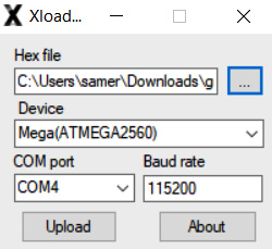
Figure 2.4 – XLoader interface
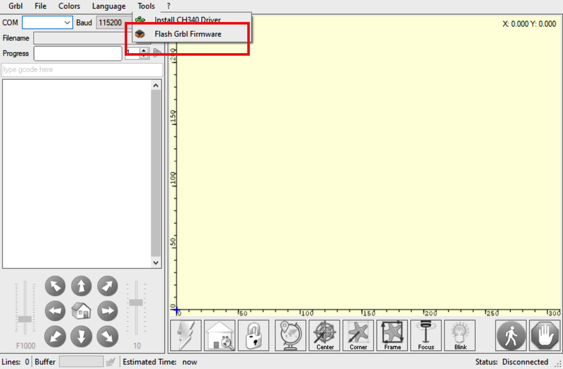
- Using LaserGRBL: This is not only a sender program but also has a built-in process for flashing firmware. I have used this program to flash firmware on both CNC and laser machines, adjust the firmware (stored permanently onboard the controller), and control some of my machines. Here is the main screen of the latest version I have. Note the menu option where GRBL can be uploaded:
Figure 2.5 – Main screen for LaserGRBL
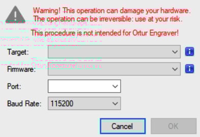
Once you select the Flash Grbl Firmware menu, you will be led to a dialog box that is very similar to XLoader’s:
Figure 2.6 – GRBL loader dialog box in LaserGRBL
There are other ways, of course, including freely available versions of Benbox (another laser engraving program that allows for custom versions of GRBL to be loaded from the Benbox vendor), but I have found the two methods I have discussed easy to use. Also worthy of mention is T2Laser, which also allows you to flash versions of GRBL from a menu of available distributions. However, your mileage may vary here, especially if you have your own custom-compiled version.
Your precompiled GRBL firmware file will have a .hex extension. This is what you will need to provide to the firmware loader. You will also need to define the target COM port, represented by your USB port. I have noticed some loaders are not too comfortable reading the firmware file from network shares, so it is recommended to have the file loaded on the PC’s local drive somewhere.
Connecting a controller to a PC
Your CNC machine will appear as a USB device on your PC. I have had excellent success connecting various desktops and laptops to many devices and controllers with little to no issues. Frequently, the device driver is automatically loaded (depending on the nature of the controller). However, failing that, you may need to load the device driver, commonly referred to as the CH340 driver. The reason for the name is that this chip (the CH340) is a common component of Arduino boards on which most hobbyist controllers are based or are clones. Load this driver (it should come on storage media with your controller) if you are unable to get your PC to recognize the board. When I am working on a from-scratch build, I check connectivity and load drivers and firmware before the board is ever connected to the CNC machine itself. Once connected, a look into Device Manager (for Windows) will show you which port your controller is on (COM4, COM5, COM6, and so on).
It is important to pay attention to the baud rate once you are connected to your controller. Using an incorrect baud rate will cause some loaders to hang, and you will have to force close them and try again. The acceptable communication speed should be published by the vendor of the controller in their specifications.
Before we move on to looking at G-code sender programs, let’s briefly go over LCD controllers. There are many alternatives here, and how you connect depends on the boards you are using. If you are using a controller such as a Mana board, there is no provision to use an LCD controller, and you are limited to using a dedicated PC for the duration of your CNC operation. On the other hand, more modern controllers will have connectors, such as those you saw in Figure 1.6 in Chapter 1, The What and Why of CNC to add an LCD.
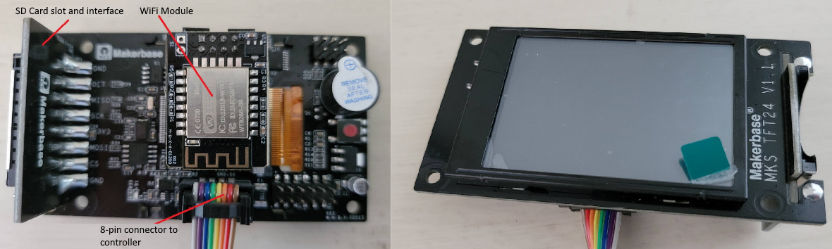
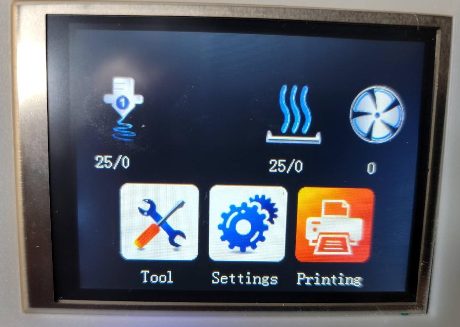
I am a big fan of the LCD controllers put out by MKS Base (or Makerbase). These come in a variety of sizes, with support for SD or microSD cards so that the LCD controller can stream G-code to your machine instead of your PC. Many of MKS’s products also include the provision for Wi-Fi to allow wireless control. Here is a photo of a 2.4” touchscreen unit I have set aside for my 3018. These units come in various other sizes, including 3.2” and 3.5”. When you purchase them, they may have the 3D printer firmware on them by default. However, MKS puts out CNC and laser firmware as well.
In Figure 2.7, you see that I have already loaded the CNC/laser firmware:
Figure 2.7 – The MKS TFT24 for my DIY 3018
The following photo shows you my FLSun Cube printer. Same LCD vendor, but a different model. The 3D printing firmware is FLSun’s modification of the baseline provided by MKS:
Figure 2.8 – Another TFT LCD with the default 3D printer firmware installed
Loading the firmware is very straightforward and requires the LCD to be connected to your controller and the controller connected to power. Prior to starting up, you load the desired firmware on an SD card and insert that into the LCD controller. When you connect power and the devices boot, the LCD automatically recognizes the firmware file and loads it. The great thing about this is that the LCD firmware will have most of the features to support upgrades, such as adding a laser, supporting endstops, and so on.
G-code sender software
Let’s review the various G-code sender programs and the ways of loading firmware onto your machine’s controller. Recall that we need senders to send the G-code to the controller because most small microcontrollers have limited memory capacity to hold more than a small number of commands. The other alternative is to use an LCD controller that allows offline operation, but you still will need sender-type software to generate the G-code file to load into the LCD controller, especially given the availability of calibration wizards such as the one in UGS. In this brief compendium, I list some of the more popular applications with as much focus on multiplatform availability as possible:
Alternatives to GRBL
While we are focusing our attention on GRBL in this book, you should also be aware of other firmware that is available, such as Maslow CNC, TinyG, Marlin, Repetier, and Klipper. For example, while Marlin is very common for 3D printers, it can be modified/adapted to run a spindle instead of a hotend (the part of the 3D printer that lays down melted plastic).
- UGS: This is one of the most common, easiest to use, and feature-rich applications. It is 100% free and is multiplatform, covering Windows, Linux, and the macOS world. It does support Raspberry Pi as the host platform as well, which means your CNC machine can have an embedded SBC PC, or simply be connected to one and make use of your machine’s onboard CNC controller. The other benefit is that you can also use its wizard to calibrate your machine (as discussed previously) and the ability to check the wiring of your motors. You can also configure your endstops or set soft limits (no physical endstops). Download it from https://winder.github.io/ugs_website/.
- OpenBuilds CONTROL: I like this fairly light application because it has the basic G-code sending functions but also includes the ability to flash firmware. As new versions of GRBL become available, you can update your machine using this software. If your PC is also on a network, you can also remote control your machine over the same network. This particular application has a huge following and can be used to control a CNC machine, a laser cutter/engraver, a drag knife, and a plasma cutter. Support for Windows, Linux, and macOS is available. Download it from https://software.openbuilds.com/.
- ChiliPeppr: If you prefer a browser-based application and can have a persistent web connection throughout your CNC machine’s run, then consider this application. ChiliPeppr not only is multiplatform but also supports multiple firmware platforms. You do need to install a small serial port JSON server to allow the application to talk to your CNC machine, but that makes for a very small footprint. Needless to say, you can use a Raspberry Pi, Linux, Mac, or Windows PC to run the machine. It does have limitations in that it can only handle 25,000 lines of G-code in its buffer. You can reach the application and download the JSON server from http://chilipeppr.com/ and go to the GRBL workspace at http://chilipeppr.com/grbl.
Other available applications include Candle, CNCjs, Easel (subscription-based), Ultimate CNC, and LinuxCNC. Consider these as well if you would like to explore alternatives to what has been presented previously.
In the laser world, I have had good experience with three applications. The first is T2 Laser (https://t2laser.wordpress.com/), which I have used to flash firmware on both laser and CNC machines and actually can be used to control both. T2 is paid software, and if you select it, you will need to decide if you are going to use it on more than one PC because the license can be tied to a PC. If you plan to use multiple machines, purchase the license that comes with a dongle that allows you to use different machines (albeit one at a time).
By far, LightBurn (https://lightburnsoftware.com/) has been my favorite (albeit paid) application for laser work. Finally, LaserGRBL (https://lasergrbl.com/) has proven to be a very robust application for my purposes.
You may also run across a software called Benbox. While commonly available with some laser machines, some units come with modified versions of GRBL specific to the board on the unit. I have occasionally resorted to Benbox to test my laser and flash GRBL but I generally don’t use it because of its limited features.
Running your first test cut
With your machine now set up and operational, it’s time to cut your first piece of material. Before we begin, we will need a wasteboard. This is a piece of material that we can make mistakes with that will protect the worktable from the cutting/carving bit should we need to cut through our workpiece. Make this out of a piece of any plywood or MDF that you can get at your local big-box DIY store. I like these to be at least 1/4” (6 mm) thick to ensure I have some leeway to stop a cut if it gets deeper than planned and to protect my metal worktable, and to drill holes to screw in clamps to hold my workpiece.
If you prefer, you can also buy wasteboards from places such as Amazon, but those are typically configured for worktables made of 80/20 extrusions, such as my machine in Figure 1.1 in Chapter 1, The What and Why of CNC. Those have countersunk holes to secure the wasteboard using T-Nuts. If you have a flat plate, as I do with my machine in the photos in this chapter, use strong binder clips to hold the wasteboard in place.
Place your workpiece on top of the wasteboard. You can secure it to the wasteboard in one of two ways:
- Option 1: Drill holes in the workpiece through and into the wasteboard and screw it onto the wasteboard directly. Make sure that your screws are countersunk so that they don’t interfere with the movement of your toolhead and that they are located outside the outermost boundaries of the object you will liberate from the workpiece. You will also need to drill a hole and put a screw through in a suitable location so that the part you cut out does not move around as it gets cut out of the workpiece. If you are only engraving to a specific depth, you don’t need to do this.
- Option 2: Use clamps that your machine may have come with to secure your workpiece. Again, place those clamps where the toolhead is unlikely to collide with them as it carves through your material. Once again, if your final product is meant to separate from the stock workpiece, you must secure it to the wasteboard so that it doesn’t come loose and mess up your cut.
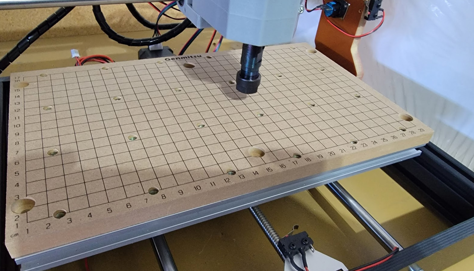
The following is an example of one of those wasteboards you can buy on one of my 3018 machines. Note all the holes in it that are countersunk with T-Nuts as well as the holes for securing it to the worktable:
Figure 2.9 – A wasteboard on one of my 3018 machines
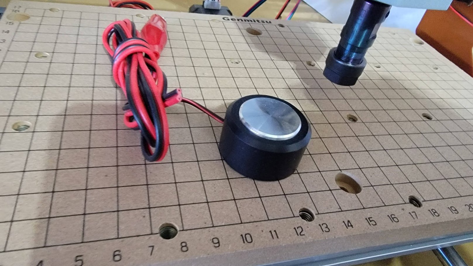
The final step before we make our first cut is to home our axes. Let’s start with the z axis. The following photo shows one of these probes that I use. The way the probe works is to complete a circuit when the carving/cutting bit’s tip touches the probe:
Figure 2.10 – One of my Z-probes for the 3018
The Z-probe typically comes with instructions, but fundamentally, you are connecting it to the controller (or if you are using an Arduino, to the A5 and GND pins) and probe header, and then you set UGS to set Z=0. There is a great video on YouTube that illustrates this far better than anything written: https://www.youtube.com/watch?v=PtJF8q3RrDo.
Next, set the X=0 and Y=0 points on your workpiece and, using UGS in the Machine Control menu, jog your axes to where you want X=0 and Y=0 to be and press the appropriate Reset Zero button.
This YouTube video also offers some additional detail on getting your axes ready: https://www.youtube.com/watch?v=A1zlL3q23HI. The presenter here uses a technique similar to how bed leveling is done on a 3D printer where Z=0 is set using a piece of paper. Something to keep in mind is that this is something you can’t really do as easily with some LCD controller firmware, which is why if I build a machine to be standalone, with an LCD controller, my preference is to have endstops to ensure the toolhead does not crash into the axes limits and I can home (set the origin) automatically every time. My DIY machine started out with no endstops but did end up with them just because it was far easier to calibrate.
With your axes set, it is time to run a test. I suggest you attempt to cut some basic shapes first: a triangle, a rectangle, and a circle. Using whatever design software you have, make these shapes, and set their depth to be smaller than the thickness of your workpiece so that you can just engrave the shapes. The easiest way to do this is to create the shape in your favorite CAD application and convert it to G-code. Load the shape in, generate the G-code, and then load the G-code into UGS (if that is what you are using). Start the spindle, execute the cut, and see the results. Once the machine is done, jog it back to its 0,0,0 location, stop the spindle if it is still turning, and turn off the machine so that you can inspect your results. Confirm the dimensions of your shape against what you intended them to be, and if everything measures up, you are ready to start doing some CNC milling.
 Argentina
 Australia
 Austria
 Belgium
 Brazil
 Bulgaria
 Canada
 Chile
Chile
 Colombia
 Cyprus
 Czechia
 Denmark
 Ecuador
 Egypt
Egypt
 Estonia
 Finland
 France
 Germany
 Great Britain
 Greece
 Hungary
 India
India
 Indonesia
 Ireland
 Italy
Italy
 Japan
Japan
 Latvia
 Lithuania
 Luxembourg
 Malaysia
 Malta
Malta
 Mexico
 Netherlands
 New Zealand
 Norway
 Philippines
 Poland
 Portugal
 Romania
 Russia
 Singapore
 Slovakia
 Slovenia
 South Africa
 South Korea
 Spain
Spain
 Sweden
 Switzerland
 Taiwan
 Thailand
 Turkey
 Ukraine
 United States