Getting data from the internet
Now that we have connected ESP8266 to the Wi-Fi network, we can receive and send data on the internet. More than this, we can read data from the input or from the sensors attached to the board and send their values to the internet.
First, let's read some data and what is more interesting than the current weather data? Let's create an account on http://www.wunderground.com and then, go to https://www.wunderground.com/weather/api/d/pricing.htm, where you will purchase a key for $0, as shown in the following image. After filling some data about the project, you will have your key:
As you can see, with the developer key, you have 10 limited calls per minute that means you can get data every 6 seconds. Later in the code, we will get the data every 10 seconds.
To check your API_KEY, use it in a browser and check that you get any data. Replace APY_KEY with your own key:
After this if you navigate to this link in your browser, http://api.wunderground.com/api/APY_KEY/conditions/q/NL/Eindhoven.json; you will get the following JSON formatted response from the wunderground.com server:
Include the ESP8266WiFi library and the ESP8266HTTPClient library that will allow you to do an HTTP GET action to get the same JSON formatted message like you get using a browser:
#include <ESP8266WiFi.h>
#include <ESP8266HTTPClient.h>
Declare the SSID and the password of your Wi-Fi network:
const char* ssid = "Your_WiFi_Name";
const char* password = "Your_WiFi_Password";
const String WUNDERGROUND_API_KEY = "YOUR_Wunderground_API_KEY";
const String WUNDERGROUND_COUNTRY = "NL";
const String WUNDERGROUND_CITY = "Eindhoven";
Construct the URL that will be used to get the data:
const String dataURL = "http://api.wunderground.com/api/"+WUNDERGROUND_API_KEY+"/conditions/q/"+WUNDERGROUND_COUNTRY+"/"+WUNDERGROUND_CITY+".json";
As usual, in the setup section, we will connect to the Wi-Fi network:
void setup() {
Serial.begin(115200);
delay(10);
Serial.println();
Serial.println();
Serial.print("Connecting to ");
Serial.println(ssid);

WiFi.begin(ssid, password);
while (WiFi.status() != WL_CONNECTED) {
delay(500);
Serial.print(".");
}
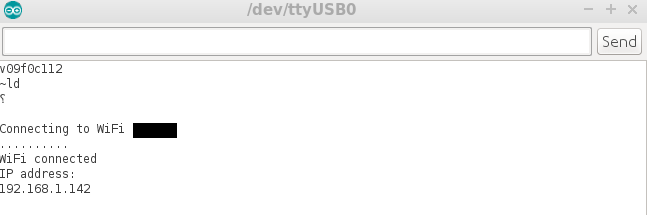
Serial.println("");
Serial.println("WiFi connected");
Serial.println("IP address: ");
Serial.println(WiFi.localIP());
} In the loop, if the Wi-Fi status is connected, then you will instantiate an HTTPClient object named http and start getting data every 10 seconds from the previously constructed link. In the payload variable, you will have the entire response from the server:
void loop()
{
if(WiFi.status() == WL_CONNECTED)
  {
HTTPClient http;
http.begin(dataURL);
inthttpCode = http.GET();

if(httpCode> 0) {
            // HTTP header has been send and Server response header has been handled
Serial.printf("[HTTP] GET... code: %d\n", httpCode);

            // file found at server
if(httpCode == HTTP_CODE_OK) {
                String payload = http.getString();
Serial.println(payload);
            }
        }
  }
delay(10000);
}
If getting data every 10 seconds is too often, let's change it to once a minute by replacing the delay(10000) call that is blocking other code executions.
So, after const String WUNDERGROUND_CITY = "Eindhoven";, add two lines of code:
const long interval = 60 * 1000;
unsigned long previousMillis = 0;
Now, the loop function will change as follows:
void loop()
{
unsigned long currentMillis = millis();
if(currentMillis - previousMillis >= interval)
  {
previousMillis = currentMillis;
if(WiFi.status() == WL_CONNECTED)
    {
HTTPClient http;
http.begin(dataURL);
inthttpCode = http.GET();

if(httpCode > 0) {
            // HTTP header has been send and Server response header has been handled
Serial.printf("[HTTP] GET... code: %d\n", httpCode);

            // file found at server
if(httpCode == HTTP_CODE_OK) {
                String payload = http.getString();
Serial.println(payload);
            }
        }
    }
  }
}
Now, the Serial Monitor will show a huge JSON with all the information about the weather from temperature to humidity, wind speed, dew point and much more every minute, as follows:
But what if you want to get only some specific data from this JSON? Fortunately, there is a Wunderground library for this. To install it, go to Sketch | Include Library | Manage Libraries and search for ESP8266 Weather Station. After installing this library, you also need to install the Json Straming Parser library that will parse the received JSON. You can follow these steps:
- Install the
ESP8266 Weather Station library:
- Also, install the
JSON Streaming Parser library:
Now, let's get the same data, so the same API_KEY will be used but the data is parsed by library functions:
- Include the headers' files for
ESP8266 Wi-Fi.h, JSONListener.h, and WundergroundClient:
#include <ESP8266WiFi.h>
#include <JsonListener.h>
#include "WundergroundClient.h"
- Define the
API_KEY and set the metric Boolean variable:
const String  WUNDERGRROUND_API_KEY = "YOUR_API_KEY";
constboolean IS_METRIC = true;
- Initialize
WundergoundClient for the metric system:
WundergroundClientweather_data(IS_METRIC);
- Also, initialize the Wi-Fi settings and constants used in getting the weather data:
const char* WIFI_SSID     = "YOUR_WIFI_SSID";
const char* WIFI_PASSWORD = "YOUR_WIFI_PASSWORD";
const String WUNDERGROUND_LANGUAGE = "EN";
const String WUNDERGROUND_COUNTRY = "NL";
const String WUNDERGROUND_CITY = "Eindhoven";
WiFiClientwifiClient;
- Initialize the
setup function to connect to the Wi-Fi network:
void setup() {
Serial.begin(115200);
delay(10);

WiFi.begin(WIFI_SSID, WIFI_PASSWORD);
delay(20);
Serial.print("Connecting to ");
Serial.println(WIFI_SSID);
while (WiFi.status() != WL_CONNECTED) {
delay(500);
Serial.print(".");
  }
Serial.println("");
Serial.println("WiFi connected!");
Serial.println();
} - In the
loop function, get the data from the wunderground.com site every minute and show it in the Serial Monitor window:
void loop() {

if ((millis() % (60 * 1000)) == 0) {
Serial.println();
Serial.println("\n\nNext Loop-Step: " + String(millis()) + ":");

weather_data.updateConditions(WUNDERGRROUND_API_KEY, WUNDERGROUND_LANGUAGE, WUNDERGROUND_COUNTRY, WUNDERGROUND_CITY);

Serial.println("wundergroundHours: " + weather_data.getHours());
Serial.println("wundergroundMinutes: " + weather_data.getMinutes());
Serial.println("wundergroundSeconds: " + weather_data.getSeconds());
Serial.println("wundergroundDate: " + weather_data.getDate());

Serial.println("wundergroundMoonPctIlum: " + weather_data.getMoonPctIlum());
Serial.println("wundergroundMoonAge: " + weather_data.getMoonAge());
Serial.println("wundergroundMoonPhase: " + weather_data.getMoonPhase());
Serial.println("wundergroundSunriseTime: " + weather_data.getSunriseTime());
Serial.println("wundergroundSunsetTime: " + weather_data.getSunsetTime());
Serial.println("wundergroundMoonriseTime: " + weather_data.getMoonriseTime());
Serial.println("wundergroundMoonsetTime: " + weather_data.getMoonsetTime());
Serial.println("wundergroundWindSpeed: " + weather_data.getWindSpeed());
Serial.println("wundergroundWindDir: " + weather_data.getWindDir());

Serial.println("wundergroundCurrentTemp: " + weather_data.getCurrentTemp());
Serial.println("wundergroundTodayIcon: " + weather_data.getTodayIcon());
Serial.println("wundergroundTodayIconText: " + weather_data.getTodayIconText());
Serial.println("wundergroundMeteoconIcon: " + weather_data.getMeteoconIcon(weather_data.getTodayIconText()));
Serial.println("wundergroundWeatherText: " + weather_data.getWeatherText());
Serial.println("wundergroundHumidity: " + weather_data.getHumidity());
Serial.println("wundergroundPressure: " + weather_data.getPressure());
Serial.println("wundergroundDewPoint: " + weather_data.getDewPoint());
Serial.println("wundergroundPrecipitationToday: " + weather_data.getPrecipitationToday());

Serial.println();
Serial.println("---------------------------------------------------/\n");
  }
} - The output for the Serial Monitor is as follows:
Note
Now, as an exercise, you can read the temperature and turn on or off an LED' if there are icing conditions or humidity and the temperature is too high outside.
 Argentina
 Australia
 Austria
 Belgium
 Brazil
 Bulgaria
 Canada
 Chile
Chile
 Colombia
 Cyprus
 Czechia
 Denmark
 Ecuador
 Egypt
Egypt
 Estonia
 Finland
 France
 Germany
 Great Britain
 Greece
 Hungary
 India
India
 Indonesia
 Ireland
 Italy
Italy
 Japan
Japan
 Latvia
 Lithuania
 Luxembourg
 Malaysia
 Malta
Malta
 Mexico
 Netherlands
 New Zealand
 Norway
 Philippines
 Poland
 Portugal
 Romania
 Russia
 Singapore
 Slovakia
 Slovenia
 South Africa
 South Korea
 Spain
Spain
 Sweden
 Switzerland
 Taiwan
 Thailand
 Turkey
 Ukraine
 United States