Until now, you have installed and configured the Arduino IDE for ESP8266 and learned how to control a LED, read an analog input, and dim a LED.
Now it is time to connect ESP8266 to Wi-Fi. Include ESP8266's Wi-Fi library and set up the SSID name and the Wi-Fi password:
#include <ESP8266WiFi.h>
const char* ssid     = "your_wifi_name";
const char* password = "your_wifi_password";
In the setup section, Serial is started and configured to send data at 115200 bps; a 10 ms delay is added to allow Serial to finish and the GPIO from 12 to 15 are configured as output and their value is set to LOW:
void setup() {
Serial.begin(115200);
delay(10);
pinMode(12, OUTPUT);
pinMode(13, OUTPUT);
pinMode(14, OUTPUT);
pinMode(15, OUTPUT);

digitalWrite(12,LOW);
digitalWrite(13,LOW);
digitalWrite(14,LOW);
digitalWrite(15,LOW);
We will start by connecting to a Wi-Fi network:
Serial.println();
Serial.println();
Serial.print("Connecting to ");
Serial.println(ssid);

WiFi.begin(ssid, password);
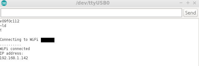
We wait until the status indicates that ESP8266 is connected to the Wi-Fi network. After this, the Wi-Fi connected message is displayed along with the IP address assigned to it by the router. Your router needs to be DHCP capable and have the DHCP feature enabled:
while (WiFi.status() != WL_CONNECTED) {
delay(500);
Serial.print(".");
  }

Serial.println("");
Serial.println("WiFi connected");
Serial.println("IP address: ");
Serial.println(WiFi.localIP());
}
In the loop section, the code checks to see whether the chip is connected to Wi-Fi and if this is true, the green LED will light on the Witty module:
void loop()
{
if(WiFi.status() == WL_CONNECTED)
digitalWrite(12, HIGH);
}
The Serial Monitor will show the IP address assigned by the router, as follows: