


 Download code from GitHub
From Source to Binaries – The Journey of a C Program
In this chapter, we will learn the basics of how compilers package EXE binaries from C code and techniques for system processes to execute. These basic concepts will build your understanding of how Windows compiles C into programs and links them across system components. You will also understand the program structure and workflow that malware analysis and evasion detection should follow.
In this chapter, we’re going to cover the following main topics:
- The simplest Windows program in C
- C compiler – assembly code generation
- Assembler – transforming assembly code into machine code
- Compiling code
- Windows linker – packing binary data into Portable Executable (PE) format
- Running compiled PE executable files as dynamic processes
The simplest Windows program in C
Any software is designed with some functionality in mind. This functionality could include tasks such as reading external inputs, processing them in the way the engineer expects them to be processed, or accomplishing a specific function or task. All of these actions require interaction with the underlying operating system (OS). A program, in order to interact with the underlying OS, must call system functions. It might be nearly impossible to design a meaningful program that does not use any system calls.
In addition to that, in Windows, the programmer, when compiling a C program, needs to specify a subsystem (you can read more about it at https://docs.microsoft.com/en-us/cpp/build/reference/subsystem-specify-subsystem); windows and console are probably the two of the most common ones.
Let’s look at a simple example of a C program for Windows:
#include <Windows.h>
Int main(void) {
MessageBoxA(0, "hi there.", "info", 0);
return 0;
}
Presented here is the most simplified C program for Windows. Its purpose is to call the USER32!MessageBox() function at the entry point of the main() function to pop up a window with the info title and the hi there content.
C compiler – assembly code generation
What is intriguing to understand in the previous section is the reason the compiler understands this C code. First, the main task for the compiler is to convert the C code into assembly code according to the C/C++ calling convention, as shown in Figure 1.1:

Figure 1.1 – x86 calling convention
Important note
For convenience and practicability, the following examples will be presented with x86 instructions. However, the methods and principles described in this book are common to all Windows systems, and the compiler examples are based on GNU Compiler Collection (GCC) for Windows (MinGW).
As different system functions (and even third-party modules) have the expected in-memory access to the memory level of the assembly code, there are several mainstream application binary interface (ABI) calling conventions for ease of management. Interested readers can refer to Argument Passing and Naming Conventions by Microsoft (https://docs.microsoft.com/en-us/cpp/cpp/argument-passing-and-naming-conventions).
These calling conventions mainly deal with several issues:
- The position where the parameters are placed in order (e.g., on a stack, in a register such as ECX, or mixed to speed up performance)
- The memory space occupied by parameters if parameters are need to be stored
- The occupied memory to be released by the caller or callee
When the compiler generates the assembly code, it will recognize the calling conventions of the system, arrange the parameters in memory according to its preference, and then call the memory address of the function with the call command. Therefore, when the thread jumps into the system instruction, it can correctly obtain the function parameter at its expected memory address.
Take Figure 1.1 as an example: we know that the USER32!MessageBoxA function prefers WINAPI calling conventions. In this calling convention, the parameter content is pushed into the stack from right to left, and the memory released for this calling convention is chosen by the callee. So after pushing 4 parameters into the stack to occupy 16 bytes in the stack (sizeof(uint32_t) x 4), it will be executed in USER32!MessageBoxA. After executing the function request, return to the next line of the Call MessageBoxA instruction with ret 0x10 and release 16 bytes of memory space from the stack (i.e., xor eax, eax).
Important note
The book here only focuses on the process of how the compiler generates single-chip instructions and encapsulates the program into an executable file. It does not include the important parts of advanced compiler theory, such as semantic tree generation and compiler optimization. These parts are reserved for readers to explore for further learning.
In this section, we learned about the C/C++ calling convention, how parameters are placed in memory in order, and how memory space is released when the program is finished.
Assembler – transforming assembly code into machine code
At this moment, you may notice that something is not quite right. The processor chips we use every day are not capable of executing text-based assembly code but are instead parsed into the machine code of the corresponding instruction set to perform the corresponding memory operations. Thus, during the compiling process, the previously mentioned assembly code is converted by the assembler into the machine code that can be understood by the chip.
Figure 1.2 shows the dynamic memory distribution of the 32-bit PE:
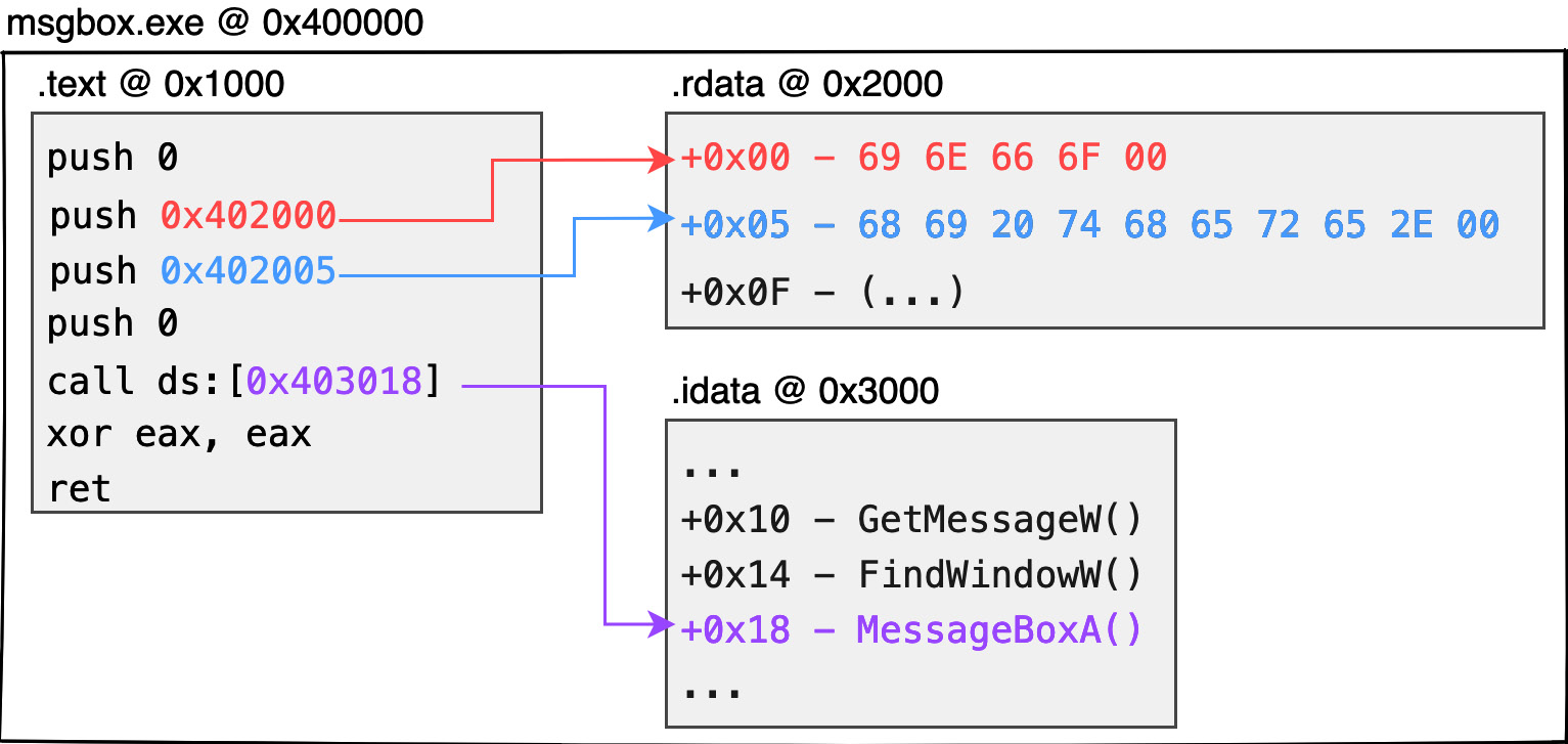
Figure 1.2 – 32-bit PE memory layout
Since the chip cannot directly parse strings such as hi there or info, data (such as global variables, static strings, global arrays, etc.) is first stored in a separate structure called a section. Each section is created with an offset address where it is expected to be placed. If the code later needs to extract resources identified during these compilation periods, the corresponding data can be obtained from the corresponding offset addresses. Here is an example:
- The aforementioned
infostring can be expressed as\x69\x6E\x66\x6F\x00in ASCII code (5 bytes in total withnullat the end of the string). The binary data of this string can be stored at the beginning of the.rdatasection. Similarly, thehi therestring can be stored closely after the previous string at the address of the.rdatasection at offset +5. - In fact, the aforementioned
call MessageBoxAAPI is not understood by the chip. Therefore, the compiler will generate anImport Address Tablestruct, which is the.idatasection, to hold the address of the system function that the current program wants to call. When needed by the program, the corresponding function address can be extracted from this table, enabling the thread to jump to the function address and continue executing the system function. - Generally speaking, it is the compiler’s practice to store the code content in the
.textsection. - Each individual running process does not have just one PE module. Either
*.EXEor*.DLLmounted in the process memory is packaged in PE format. - In practice, each module loaded into the memory must be assigned an image base address to hold all contents of the module. In the case of a 32-bit
*.EXE, the image base address would normally be0x400000. - The absolute address of each piece of data in the dynamic memory will be the image base address of this module + the section offset + the offset of the data on the section. Take the
0x400000image base address as an example. If we want to get theinfostring, the expected content will be placed at0x402000(0x400000 + 0x2000 + 0x00). Similarly,hi therewould be at0x402005, and theMessageBoxApointer would be stored at0x403018.
Important note
There is no guarantee that the compiler will generate .text, .rdata, and .idata sections in practice, or that their respective uses will be for these functions. Most compilers follow the previously mentioned principles to allocate memory. Visual Studio compilers, for example, do not produce executable programs with .idata sections to hold function pointer tables, but rather, in readable and writable .rdata sections.
What is here is only a rough understanding of the properties of block and absolute addressing in the dynamic memory; it is not necessary to be obsessed with understanding the content, attributes, and how to fill them correctly in practice. The following chapters will explain the meaning of each structure in detail and how to design it by yourself.
In this section, we learned about the transformation to machine code operations during program execution, as well as the various sections and offsets of data stored in memory that can be accessed later in the compiling process.
Compiling code
As mentioned earlier, if the code contains chip-incomprehensible strings or text-based functions, the compiler must first convert them to absolute addresses that the chip can understand and then store them in separate sections. It is also necessary to translate the textual script into native code or machine code that the chip can recognize. How does this work in practice?
In the case of Windows x86, the instructions executed on the assembly code are translated according to the x86 instruction set. The textual instructions are translated and encoded into machine code that the chip understands. Interested readers can search for x86 Instruction Set on Google to find the full instruction table or even encode it manually without relying on a compiler.
Once the compiler has completed the aforementioned block packaging, the next stage is to extract and encode the textual instructions from the script, one by one, according to the x86 instruction set, and write them into the .text section that is used to store the machine code.
As shown in Figure 1.3, the dashed box is the assembly code in the text type obtained from compiling the C/C++ code:
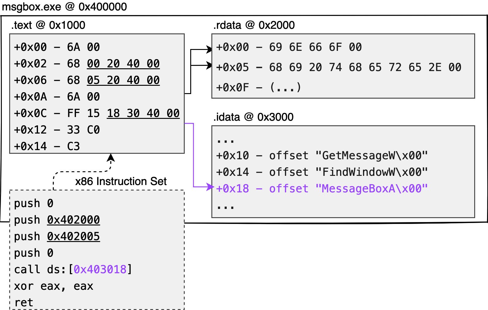
Figure 1.3 – Native code generation
You can see the first instruction is push 0, which pushes 1 byte of data onto the stack (saved as 4 bytes), and 6A 00 is used to represent this instruction. The push 0x402005 instruction pushes 4 bytes onto the stack at once, so push 68 50 20 40 00 is used to achieve a longer push. call ds:[0x403018] is the address of the 4 bytes, and the long call of machine code, FF 15 18 30 40 00, is used to represent this instruction.
Although Figure 1.3 shows the memory distribution of the dynamic msgbox.exe file, the file produced by the compiler is not yet an executable PE file. Rather, it is a file called a Common Object File Format (COFF) or an object file, as some people call it, which is a wrapper file specifically designed to record the various sections produced by the compiler. The following figure shows the COFF file obtained by compiling and assembling the source code with the gcc -c command, and viewing its structure with a well-known tool, PEview.
As shown in Figure 1.4, there is an IMAGE_FILE_HEADER structure at the beginning of the COFF file to record how many sections are included:
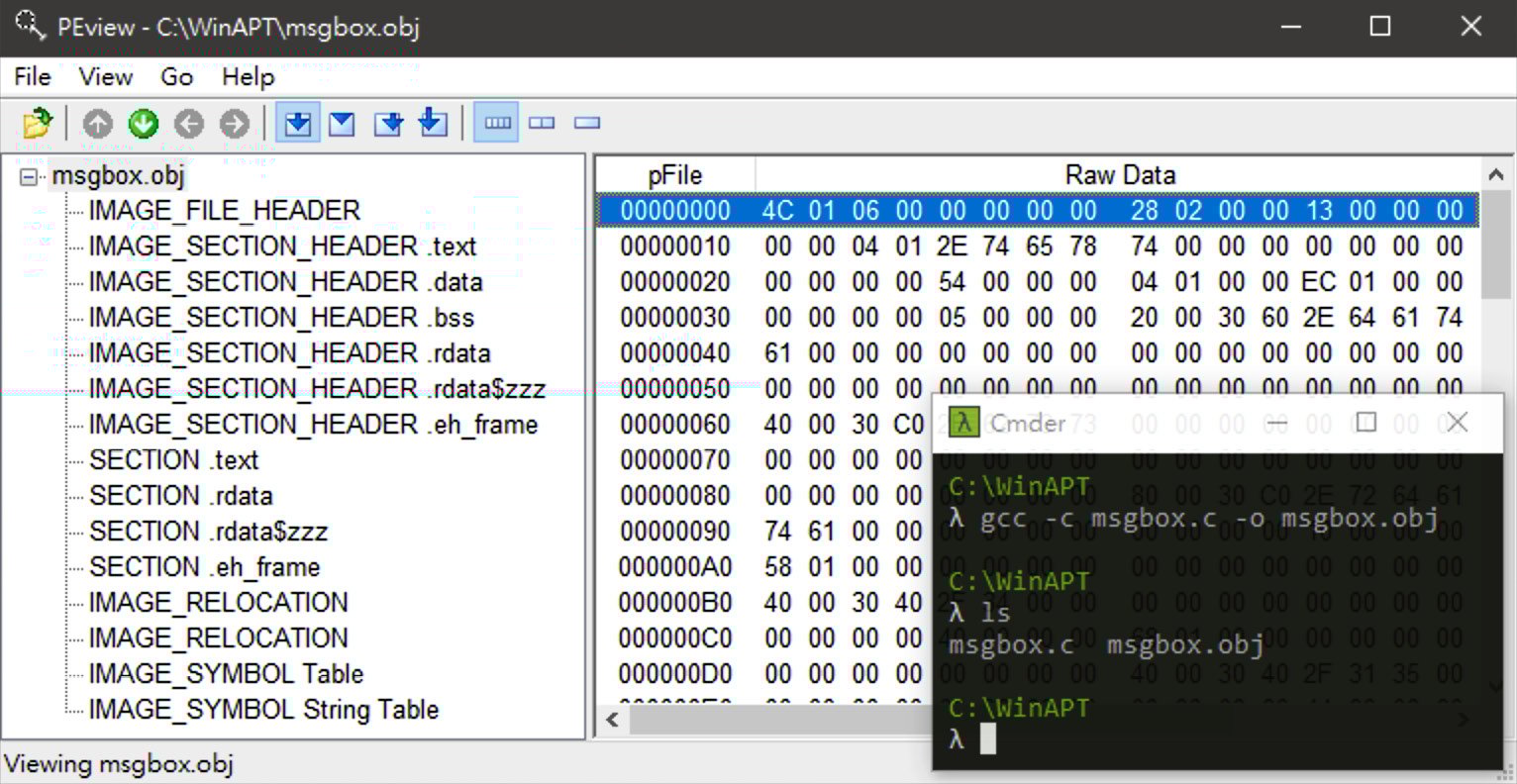
Figure 1.4 – COFF
At the end of this structure is a whole array of IMAGE_SECTION_HEADER to record the current location and size of the content of each section in the file. Closely attached at the end of this array is the substantive content of each section. In practice, the first section will usually be the content of the .text section.
In the next stage, the Linker is responsible for adding an extra piece of the COFF file to the application loader, which will become our common EXE program.
Important note
In the case of x86 chip systems, it is customary to reverse the pointer and digit per bit into the memory when encoding. This practice is called little-endian, as opposed to a string or array that should be arranged from lowest to highest address. The data arrangement of multiple bytes varies according to the chip architecture. Interested readers can refer to the article How to write endian-independent code in C (https://developer.ibm.com/articles/au-endianc/).
In this section, we learned about the COFF, which is used to record the contents in the memory of the various sections recorded by the compiler.
Windows linker – packing binary data into PE format
In the previous section, we assumed some memory distribution during the program's compilation. For example, the default EXE module image base should be at 0x400000 so that executable content should be placed. The .text section should be placed at 0x401000 above its image base. As we said, the .idata section is used to store the import address table, so the question is who or what is responsible for filling the import address table?
The answer is that every OS has an application loader, which is designed to fill all these tasks correctly when creating a process from a static program. However, there is a lot of information that will only be known at the compiling time and not by the system developer, such as the following:
- Does the program want to enable Address Space Layout Randomization (ASLR) or Data Execution Prevention (DEP)?
- Where is the
main(int, char)function in the.textsection written by the developer? - How much of the total memory is used by the execution module during the dynamic phase?
Microsoft has therefore introduced the PE format, which is essentially an extension to the COFF file, with an additional optional header structure to record the information required by the Windows program loader to correct the process. The following chapters will focus on playing with the various structures of the PE format so that you can write an executable file by hand on a whiteboard.
All you need to know now is that a PE executable has some key features:
- Code content: Usually stored as machine code in the
.textsection - Import address tables: To allow the loader to fill in the function addresses and enable the program to get them correctly
- Optional header: This structure allows the loader to read and know how to correct the current dynamic module
Here is an example in Figure 1.5:

Figure 1.5 – Minimalist architecture of the program
msgbox.exe is a minimalist Windows program with only three sections: .text, .rdata, and .idata. After dynamic execution, the system application loader sequentially extracts the content of the three sections and writes them each to the offset of 0x1000, 0x2000, and 0x3000 relative to the current PE module (msgbox.exe).
In this section, we learned that the application loader is responsible for correcting and filling the program content to create a static program file into a process.
Running static PE files as dynamic processes
At this point, you have a general idea of how a minimal program is generated, compiled, and packaged into an executable file by the compiler in the static phase. So, the next question is, What does the OS do to get a static program running?
Figure 1.6 shows the process structure of how an EXE program is transformed from a static to a dynamic process under the Windows system:

Figure 1.6 – Dynamic operation of the process hatching flow
Note that this is different from the process hatching process in the latest version of Windows. For the sake of explanation, we'll ignore the processes of privilege escalation, the patching mechanism, and kernel generation, and only talk about how a static program is correctly parsed and run from a single execution.
On Windows systems, all processes must be hatched by the parent process by interrupting the system function to jump to the kernel level. For example, a parent process is currently trying to run the cmd.exe /c whoami command, which is an attempt to hatch the cmd.exe static file into a dynamic process and assign its parameters to /c whoami.
So, what happens in the whole process? As shown in Figure 1.6, these are the steps:
- The parent process makes a request to the kernel with
CreateProcess, specifying to generate a new process (child process). - Next, the kernel will produce a new process container and fill the execution code into the container with file mapping. The kernel will create a thread to assign to this child process, which is commonly known as the main thread or GUI thread. At the same time, the kernel will also arrange a block of memory in Userland’s dynamic memory to store two structural blocks: a process environment block (PEB) for recording the current process environment information and a thread environment block (TEB) for recording the first thread environment information. The details of these two structures will be fully introduced in Chapter 2, Process Memory – File Mapping, PE Parser, tinyLinker, and Hollowing, and in Chapter 3, Dynamic API Calling – Thread, Process, and Environment Information.
- The
NtDLLexport function,RtlUserThreadStart, is the main routing function for all threads and is responsible for the necessary initialization of each new thread, such as the generation of structured exception handling (SEH). The first thread of each process, that is, the main thread, will executeNtDLL!LdrInitializeThunkat the user level and enter theNtDLL!LdrpInitializeProcessfunction after the first execution. It is the executable program loader, responsible for the necessary correction of the PE module loaded into the memory. - After the execution loader completes its correction, it jumps back to the current execution entry (
AddressOfEntryPoint), which is the developer’smainfunction.
Important note
From a code perspective, a thread can be thought of as a person responsible for executing code, and a process can be thought of as a container for loading code.
The kernel layer is responsible for file mapping, which is the process of placing the program content based on the preferred address during the compiling period. For example, if the image base address is 0x400000 and the .text offset is 0x1000, then the file mapping process is essentially a simple matter of requesting a block of memory at the 0x400000 address in the dynamic memory and writing the actual contents of .text to 0x401000.
In fact, the loader function (NtDLL! LdrpInitializeProcess) does not directly call AddressOfEntryPoint after execution; instead, the tasks corrected by the loader and the entry point are treated as two separate threads (in practice, two thread contexts will be opened). NtDLL!NtContinue will be called after the correction and will hand over the task to the entry to continue execution as a thread task schedule.
The entry point of the execution is recorded in NtHeaders→OptionalHeader.AddressOfEntryPoint of the PE structure, but it is not directly equivalent to the main function of the developer. This is for your understanding only. Generally speaking, AddressOfEntryPoint points to the CRTStartup function (C++ Runtime Startup), which is responsible for a series of C/C++ necessity initialization preparations (e.g., cutting arguments into developer-friendly argc and argv inputs, etc.) before calling the developer’s main function.
In this section, we learned how EXE files are incubated from static to dynamically running processes on the Windows system. With the process and thread, and the necessary initialization actions, the program is ready to run.
Summary
In this chapter, we explained how the OS converts C code into assembly code via a compiler and into executable programs via a linker.
The next chapter will be based on this framework and will take you through a hands-on experience of the entire flowchart in several C/C++ labs. Through the following chapters, you will learn the subtleties of PE format design by building a compact program loader and writing an executable program yourself.