


In this chapter, we will cover the following recipes:
Programming shaders in OpenGL ES shading language 3.0
Loading and compiling a shader program
Linking a shader program
Checking errors in OpenGL ES 3.0
Using the per-vertex attribute to send data to a shader
Using uniform variables to send data to a shader
Programming OpenGL ES 3.0 Hello World Triangle
Using JNI on Android to communicate with C/C++
Developing an Android OpenGL ES 3.0 application
Developing an iOS OpenGL ES 3.0 application
OpenGL ES 3.0 stands for Open Graphics Library for embedded systems version 3.0. It is a set of standard API specifications established by the Khronos Group. The Khronos Group is an association of members and organizations that are focused on producing open standards for royalty-free APIs. OpenGL ES 3.0 specifications were publicly released in August 2012. These specifications are backward compatible with OpenGL ES 2.0, which is a well-known de facto standard for embedded systems to render 2D and 3D graphics. Embedded operating systems such as Android, iOS, BlackBerry, Bada, Windows, and many others support OpenGL ES.
OpenGL ES 3D APIs are the stripped-down version of OpenGL, which is a cross-platform standard 3D API on a desktop environment for Linux, various flavors of UNIX, Mac OS, and Windows. This stripped-down version is mainly focused on providing the capabilities of 3D graphics as per embedded system requirements such as low-power consumption, limited processing capabilities, and small memory footprints.
The OpenGL ES 2.0/3.0 graphics library is shading-language compliant, unlike its predecessor 1.1. The major difference between OpenGL ES 1.1 and OpenGL ES 2.0/3.0 is the graphics pipeline architecture. The graphics pipeline framework for the former is known as a fixed function pipeline, and for the latter, it is a programmable pipeline. These frameworks are explained in the following table:
|
OpenGL ES version |
Architecture pipeline type |
Need shader |
|---|---|---|
|
1.1 |
Fixed function pipeline |
No |
|
2.0 and 3.0 |
Programmable pipeline |
Yes |
A pipeline is a set of events that occur in a predefined fixed sequence, from the moment input data is given to the graphic engine to the output generated data for rendering the frame. A frame refers to an image produced as an output on the screen by the graphics engine.
Each frame in a fixed function pipeline architecture is generated by a fixed set of algorithms, calculations, and sequences of events. You can only specify what you want, but not how it will be calculated. For example, if you are interested in applying some light shading on your solid sphere model, then you will need to specify the light position, its intensity, material properties, and other similar attributes. The fixed pipeline uses these inputs and takes care of all the physics and mathematics required to generate the light shading. Therefore, you don't need to worry, as the how factor is fully abstracted. The good side of the fixed function pipeline is that it is very easy to understand and quick to program.
In contrast, with the programmable pipeline architecture, you not only need to specify what you want to achieve, but you also need to mention how to implement it. This pipeline also provides extraordinary capabilities through shaders. Shaders are the special programs that control your scene's geometry and shading appearance. For example, in order to achieve the same light-shading effect on solid sphere, you must know the basics of physics and mathematics in order to program the light-shading techniques. Since you are programming the behavior of light shading, you can fully control it. This opens up endless possibilities to create infinite shading effects. Shaders are super fast. They execute rendering in parallel-processing mode using Graphics Processing Unit (GPU).
Now, the question is if fixed function pipeline is doing all the light physics and mathematical abstraction, then why do we need to understand it for programmable pipelines? The reason is with fixed pipeline, we can only do finite graphics capabilities, and it cannot be used to produce realistic graphics effectively. However, the programmable pipeline opens endless possibilities and opportunities to produce state-of-art graphics rendering.
This chapter will provide OpenGL ES 3.0 development on Android and iOS. We will begin this chapter by understanding the basic programming of the OpenGL ES 3.0 with the help of a simple example to render a triangle on the screen. You will learn how to set up and create your first application on both platforms step by step.
Understanding EGL: The OpenGL ES APIs require the EGL as a prerequisite before they can effectively be used on the hardware devices. The EGL provides an interface between the OpenGL ES APIs and the underlying native windowing system. Different OS vendors have their own ways to manage the creation of drawing surfaces, communication with hardware devices, and other configurations to manage the rendering context. EGL provides an abstraction, how the underlying system needs to be implemented in a platform-independent way. The platform vendor's SDK provides an implementation of EGL through their own framework. These can be directly used in the application to accomplish the development task quickly. For example, the iOS provides EGL through the EAGL (EAGLContext) class in conjunction with GLkit to create GLSurface. On the Android platform, the GLView class provides interfaces for EGL through GLView.EGLContextFactory and GLView.EGLConfigChooser.
The EGL provides two important things to OpenGL ES APIs:
Rendering context: This stores the data structure and important OpenGL ES states that are essentially required for rendering purpose
Drawing surface: This provides the drawing surface to render primitives
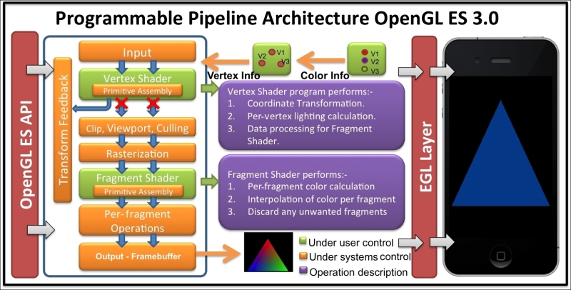
The following screenshot shows the programmable pipeline architecture of OpenGL ES 3.0:
EGL works on top of the native windowing system, such as WGL (Windows), GLX, or X-Windows (Linux), or Mac OS X's Quartz. With EGL specifications, cross-platform development becomes easier.
EGL provides the following responsibilities:
Checking the available configuration to create rendering context of the device windowing system
Creating the OpenGL rendering surface for drawing
Compatibility and interfacing with other graphics APIs such as OpenVG, OpenAL, and so on
Managing resources such as texture mapping
Note
You can refer to the following link for more information on EGL http://www.khronos.org/egl.
OpenGL ES shading language 3.0 (also called as GLSL) is a C-like language that allows us to writes shaders for programmable processors in the OpenGL ES processing pipeline. Shaders are the small programs that run on the GPU in parallel. Without these programs, it is impossible to write OpenGL ES 3.0 programs.
OpenGL ES 3.0 supports two type of shaders: vertex shader and fragment shader. Each shader has specific responsibilities. For example, the vertex shader is used to process geometric vertices; however, the fragment shader processes the pixels or fragment color information. More specially, the vertex shader processes the vertex information by applying 2D/3D transformation. The output of the vertex shader goes to the rasterizer where the fragments are produced. The fragments are processed by the fragment shader, which is responsible for coloring them.
The order of execution of the shaders is fixed; the vertex shader is always executed first, followed by the fragment shader. Each shader can share its processed data with the next stage in the pipeline. The GLSL facilitates user-defined variables such as C language; these variables are used for input and output purposes. There are also inbuilt variables that track the states in the shaders to make decisions while processing data in these shaders. For example, the fragment shader provides a state where the incoming fragment can be tested to see if it belongs to the front face or back face of a polygon.
There are two types of processors in the OpenGL ES 3.0 processing pipeline to execute vertex shader and fragment shader executables; it is called programmable processing unit:
Vertex processor: The vertex processor is a programmable unit that operates on the incoming vertices and related data. It uses the vertex shader executable and run it on the vertex processor. The vertex shader needs to be programmed, compiled, and linked first in order to generate an executable, which can then be run on the vertex processor.
Fragment processor: This is another programmable unit in the OpenGL ES pipeline that operates on fragments and related data. The fragment processor uses the fragment shader executable to process fragment or pixel data. The fragment processor is responsible for calculating colors of the fragment. They cannot change the position of the fragments. They also cannot access neighboring fragments. However, they can discard the pixels. The computed color values from this shader are used to update the framebuffer memory and texture memory.
Here are the sample codes for vertex and fragment shaders:
Program the following vertex shader and store it into the
vertexShadercharacter type array variable:#version 300 es in vec4 VertexPosition; in vec4 VertexColor; uniform float RadianAngle; out vec4 TriangleColor; mat2 rotation = mat2(cos(RadianAngle),sin(RadianAngle), -sin(RadianAngle),cos(RadianAngle)); void main() { gl_Position = mat4(rotation)*VertexPosition; TriangleColor = VertexColor; }Program the following fragment shader and store it into another character array type variable called
fragmentShader:#version 300 es precision mediump float; in vec4 TriangleColor; out vec4 FragColor; void main() { FragColor = TriangleColor; };
Like most of the languages, the shader program also starts its control from the main() function. In both shader programs, the first line, #version 300 es, specifies the GLES shading language version number, which is 3.0 in the present case. The vertex shader receives a per-vertex input variable VertexPosition. The data type of this variable is vec4, which is one of the inbuilt data types provided by OpenGL ES Shading Language. The in keyword in the beginning of the variable specifies that it is an incoming variable and it receives some data outside the scope of our current shader program. Similarly, the out keyword specifies that the variable is used to send some data value to the next stage of the shader. Similarly, the color information data is received in VertexColor. This color information is passed to TriangleColor, which sends this information to the fragment shader, and is the next stage of the processing pipeline.
The RadianAngle is a uniform type of variable that contains the rotation angle. This angle is used to calculate rotation matrix into rotation. Refer to following See also section to get reference for the per-vertex attribute and uniform variables.
The input values received by VertexPosition are multiplied using the rotation matrix, which will rotate the geometry of our triangle. This value is assigned to gl_Position. The gl_Position is an inbuilt variable of the vertex shader. This variable is supposed to write the vertex position in the homogeneous form. This value can be used by any of the fixed functionality stages, such as primitive assembly, rasterization, culling, and so on. Refer to the The fixed function and programmable pipeline architecture recipe in Appendix, Supplementary Information on OpenGL ES 3.0, for more information on the fixed stages.
In the fragment shader, the precision keyword specifies the default precision of all floating types (and aggregates, such as mat4 and vec4) to be mediump. The acceptable values of such declared types need to fall within the range specified by the declared precision. OpenGL ES Shading Language supports three types of the precision: lowp, mediump and highp. Specifying the precision in the fragment shader is compulsory. However, for vertex, if the precision is not specified, it is consider to be highest (highp).
FragColor is an out variable, which sends the calculated color values for each fragment to the next stage. It accepts the value in the RGBA color format.
As mentioned there are three types of precision qualifiers, the following table describes these:
|
Qualifier |
Description |
|---|---|
|
|
These variables provide the maximum range and precision. But they can cause operations to run more slowly on some implementations; generally, vertices have high precision. |
|
|
These variables may typically be used to store high dynamic range colors and low precision geometry. |
|
|
These variables may typically be used to store 8-bit color values. |
The range and precision of these precision qualifiers are shown here:
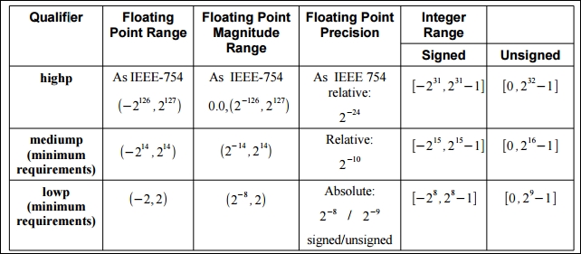
The preceding image is taken from page 48 of https://www.khronos.org/registry/gles/specs/3.0/GLSL_ES_Specification_3.00.3.pdf.
Tip
Downloading the example code
You can download the example code files for all Packt books you have purchased from your account at http://www.packtpub.com. If you purchased this book elsewhere, you can visit http://www.packtpub.com/support and register to have the files e-mailed directly to you.
The shader program created in the previous recipe needs to be loaded and compiled into a binary form. This recipe will be helpful in understanding the procedure of loading and compiling a shader program.
Compiling and linking a shader is necessary so that these programs are understandable and executable by the underlying graphics hardware/platform (that is, the vertex and fragment processors).
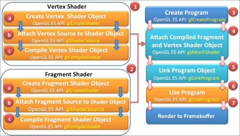
The following figure provides an overview of the complete process of creating a shader executable. The different number labels help us understand the order of flow in the build process. Each stage within the build process is marked with the respective OpenGL ES APIs responsible for it.
In order to load and compile the shader source, use the following steps:
Create a
NativeTemplate.h/NativeTemplate.cppand define a function namedloadAndCompileShaderin it. Use the following code, and proceed to the next step for detailed information about this function:GLuint loadAndCompileShader(GLenum shaderType, const char* sourceCode) { // Create the shader GLuint shader = glCreateShader(shaderType); if ( shader ) { // Pass the shader source code glShaderSource(shader, 1, &sourceCode, NULL); // Compile the shader source code glCompileShader(shader); // Check the status of compilation GLint compiled = 0; glGetShaderiv(shader,GL_COMPILE_STATUS,&compiled); if (!compiled) { // Get the info log for compilation failure GLint infoLen = 0; glGetShaderiv(shader,GL_INFO_LOG_LENGTH, &infoLen); if (infoLen) { char* buf = (char*) malloc(infoLen); if (buf) { glGetShaderInfoLog(shader, infoLen, NULL, buf); printf("Could not compile shader %s:" buf); free(buf); } // Delete the shader program glDeleteShader(shader); shader = 0; } } } return shader; }This function is responsible for loading and compiling a shader source. The argument
shaderTypeaccepts the type of shader that needs to be loaded and compiled; it can beGL_VERTEX_SHADERorGL_FRAGMENT_SHADER. ThesourceCodespecifies the source program of the corresponding shader.Create an empty shader object using the
glCreateShaderOpenGL ES 3.0 API. This shader object is responsible for loading the vertex or fragment source code depending on the specifiedshaderTypeparameter:Syntax:
GLuint glCreateShader( Glenum shaderType);
This API returns a non-zero value if the object is successfully created. This value is used as a handle to reference this object. On failure, this function returns
0. TheshaderTypeargument specifies the type of the shader to be created. It must be eitherGL_VERTEX_SHADERorGL_FRAGMENT_SHADER:// Create the shader object GLuint shader = glCreateShader(shaderType);
Note
Unlike in C++, where object creation is transparent, in OpenGL ES, the objects are created behind the curtains. You can access, use, and delete the objects as and when required. All the objects are identified by a unique identifier, which can be used for programming purposes.
The created empty shader object (
shader) needs to be bound first with the shader source in order to compile it. This binding is performed by using theglShaderSourceAPI:// Load the shader source code glShaderSource(shader, 1, &sourceCode, NULL);
The API sets the shader code string in the shader object,
shader. The source string is simply copied in the shader object; it is not parsed or scanned.Syntax:
void glShaderSource(GLuint shader, GLsizei count, const GLchar * const *string, const GLint *length);
Variable
Description
shaderThis is the handle of the shader object whose source code needs to bind
countThis is the number of elements in the string and length arrays
stringThis specifies the array of pointers to strings containing source code that needs to be loaded
lengthThis specifies the array of string lengths
The count specifies the number of strings in the array. If the length array is
NULL, this means that all the strings are null terminated. If the values inside in this array are non-zero, it specifies the length of the corresponding string. Any value less than0is assumed it to be a null-terminated string.Compile the shader using the
glCompileShaderAPI. It accepts a shader object handle shader:glCompileShader(shader); // Compile the shader
Syntax:
void glCompileShader (GLuint shader);
Variable
Description
shaderThis is the handle of the shader object that needs to be compiled
The compilation status of the shader is stored as a state of the shader object. This state can be retrieved using the
glGetShaderivOpenGL ES API:GLint compiled = 0; // Check compilation status glGetShaderiv(shader, GL_COMPILE_STATUS, &compiled);The
glGetShaderivAPI accepts the handle of the shader andGL_COMPILE_STATUSas an argument to check the status of the compilation. It retrieves the status in params. The params returnsGL_TRUEif the last compilation was successful. Otherwise, it returnsGL_FALSE.Syntax:
void glGetShaderiv(GLuint shader, GLenum pname, GLint *params);
Variable
Description
shaderThis is the handle of the shader object whose compilation status needs to be checked.
pnameThis specifies the object's state parameter. The symbolic names accepted are
GL_SHADER_TYPE,GL_DELETE_STATUS,GL_COMPILE_STATUS,GL_INFO_LOG_LENGTH, andGL_SHADER_SOURCE_LENGTH.paramsThis returns the requested object parameter state.
In the case of compilation failure, the
glGetShaderivAPI can also be used to retrieve the information log from the OpenGL ES state machine by passingGL_INFO_LOG_LENGTHas the parameter. TheinfoLenreturns the length of the information log. If the returned value is0, it means there is no information log. If theinfoLenvalue is greater than0, then the information log message can be retrieved usingglGetShaderInfoLog:if (!compiled) { // Handle Errors GLint infoLen = 0; // Check error string length glGetShaderiv(shader, GL_INFO_LOG_LENGTH, &infoLen); . . . . . }
Use
glGetShaderInfoLogto get the error report:Syntax:
void glGetShaderInfoLog(GLuint shader, GLsizei maxLength, GLsizei*length, GLchar* infoLog);
Variable
Description
shaderThis is the handle of the shader object whose information log is required
maxLengthThis is the size of the character buffer to store the returned information log
lengthThis is the length of the string returned by the information length
infoLogThis specifies array of characters
The shader is deleted if the shader source cannot be compiled. Delete the shader object using the
glDeleteShaderAPI.Syntax:
void glDeleteShader(GLuint shader);
Variable
Description
shaderThis is the handle of the shader object that needs to be deleted
Return the shader object ID if the shader is compiled successfully:
return shader; // Return the shader object ID
The loadAndCompileShader function first creates an empty shader object. This empty object is referenced by the shader variable. This object is bound with the source code of the corresponding shader. The source code is compiled through a shader object using the glCompileShader API. If the compilation is successful, the shader object handle is returned successfully. Otherwise, the shader object returns 0 and needs to be deleted explicitly using glDeleteShader. The status of the compilation can be checked using glGetShaderiv with GL_COMPILE_STATUS.
In order to differentiate among various versions of OpenGL ES and GL Shading Language, it is useful to get this information from the current driver of your device. This will be helpful to make the program robust and manageable by avoiding errors caused by version upgrade or application being installed on older versions of OpenGL ES and GLSL. The other vital information can be queried from the current driver, such as the vendor, renderer, and available extensions supported by the device driver. This information can be queried using the glGetString API. This API accepts a symbolic constant and returns the queried system metrics in the string form. The printGLString wrapper function in our program helps in printing device metrics:
static void printGLString(const char *name, GLenum s) {
    printf("GL %s = %s\n", name, (const char *) glGetString(s));
}
// Print the OpenGL ES system metrics
void printOpenGLESInfo(){
   printGLString("Version",    GL_VERSION);
   printGLString("Vendor",    GL_VENDOR);
   printGLString("Renderer",    GL_RENDERER);
   printGLString("Extensions",    GL_EXTENSIONS);
   printGLString("GLSL version",  GL_SHADING_LANGUAGE_VERSION);
}Linking is a process of aggregating a set (vertex and fragment) of shaders into one program that maps to the entirety of the programmable phases of the OpenGL ES 3.0 graphics pipeline. The shaders are compiled using shader objects, as we created in the previous recipe. These objects are used to create special objects called program objects to link it to the OpenGL ES 3.0 pipeline. In this recipe, you will understand the shader linking process.
The following instructions provides a step-by-step procedure to link as shader:
Create a new function,
linkShader, inNativeTemplate.cpp.This will be the wrapper function to link a shader program to the OpenGL ES 3.0 pipeline. Follow these steps to understand this program in detail:GLuint linkShader(GLuint vertShaderID,GLuint fragShaderID){ if (!vertShaderID || !fragShaderID){ // Fails! return return 0; } // Create an empty program object GLuint program = glCreateProgram(); if (program) { // Attach vertex and fragment shader to it glAttachShader(program, vertShaderID); glAttachShader(program, fragShaderID); // Link the program glLinkProgram(program); GLint linkStatus = GL_FALSE; glGetProgramiv(program, GL_LINK_STATUS, &linkStatus); if (linkStatus != GL_TRUE) { GLint bufLength = 0; glGetProgramiv(program, GL_INFO_LOG_LENGTH, &bufLength); if (bufLength) { char* buf = (char*) malloc(bufLength); if(buf) { glGetProgramInfoLog(program,bufLength,NULL,buf); printf("Could not link program:\n%s\n", buf); free(buf); } } glDeleteProgram(program); program = 0; } } return program; }Create a program object with
glCreateProgram. This API creates an empty program object using which the shader objects will be linked:GLuint program = glCreateProgram(); //Create shader program
Syntax:
GLint glCreateProgram( void);
Attach shader objects to the program object using the
glAttachShaderAPI. It is necessary to attach the shaders to the program object in order to create the program executable:// Attach the vertex and fragment shader glAttachShader(program, vertShaderID); glAttachShader(program, fragShaderID);
Here is the syntax of the
glAttachShaderAPI:Syntax:
void glAttachShader(GLuint program, GLuint shader);
Variable
Description
programThis specifies the program object to which the shader object (shader) will be attached
shaderThis specifies the program object that is to be attached
The shader must be linked to the program in order to create the program executable. The linking process is performed using
glLinkProgram. This API links the program object, specified by theprogramidentifier, which must contain the attached vertex and fragment shaders objects:glLinkProgram(program); // Link the shader program
The status of the link operation can be checked using
glGetShaderiv. This API accepts program andGL_LINK_STATUSas arguments. This will returnGL_TRUEif the last link on program was successful; otherwise, it will returnGL_FALSE.Syntax:
void glGetProgramiv(GLuint program, GLenum pname, GLint *params);
Variable
Description
programThis specifies the program object to be queried
pnameThis specifies symbolic state parameters
paramsThis returns the requested program object parameter state
If link status is returned
GL_FALSE, the program object must release its allocated memory usingglDeleteProgram. This API undoes all the effects ofglCreateProgram. It also invalidates the handle with which it was associated.Syntax:
void glDeleteProgram(Glint program);
Variable
Description
programThis specifies the handle of program that needs to be deleted
The linkShader wrapper function links the shader. It accepts two parameters: vertShaderID and fragShaderID. They are identifiers of the compiled shader objects. The createProgram function creates a program object. It is another OpenGL ES object to which shader objects are attached using glAttachShader. The shader objects can be detached from the program object if they are no longer in need. The program object is responsible for creating the executable program that runs on the programmable processor. A program in OpenGL ES is an executable in the OpenGL ES 3.0 pipeline that runs on the vertex and fragment processors.
The program object is linked using glLinkShader. If the linking fails, the program object must be deleted using glDeleteProgram. When a program object is deleted it automatically detached the shader objects associated with it. The shader objects need to be deleted explicitly. If a program object is requested for deletion, it will only be deleted until it's not being used by some other rendering context in the current OpenGL ES state.
If the program's object link successfully, then one or more executable will be created, depending on the number of shaders attached with the program. The executable can be used at runtime with the help of the glUseProgram API. It makes the executable a part of the current OpenGL ES state.
While programming, it is very common to get unexpected results or errors in the programmed source code. It's important to make sure that the program does not generate any error. In such a case, you would like to handle the error gracefully. This section will guide us to track errors in the OpenGL ES 3.0 and GL shading language.
OpenGL ES 3.0 allows us to check the error using a simple routine called getGlError. The following wrapper function prints all the error messages occurred in the programming:
static void checkGlError(const char* op) {
     for(GLint error = glGetError(); error; error= glGetError()){
        printf("after %s() glError (0x%x)\n", op, error);
     }
}
The getGlError returns an error code. The following table describes these errors:
Syntax:
GLenum glGetError(void);
|
Error code |
Description |
|---|---|
|
|
This indicates if no error found |
|
|
This indicates if the |
|
|
This indicates if the numeric argument is out of range |
|
|
This indicates if the operation illegal in current state |
|
|
This indicates if the command would cause a stack overflow |
|
|
This indicates if the command would cause a stack underflow |
|
|
This indicates if there is not enough memory left to execute the command |
Here are few examples of code that produce OpenGL ES errors:
// Gives a GL_INVALID_ENUM error
glEnable(GL_TRIANGLES);

// Gives a GL_INVALID_VALUE
// when attribID >= GL_MAX_VERTEX_ATTRIBS
glEnableVertexAttribArray(attribID);
When OpenGL ES detects an error, it records the error into an error flag. Each error has a unique numeric code and symbolic name. OpenGL ES does not track each time an error has occurred. Due to performance reasons, detecting errors may degrade the rendering performance therefore, the error flag is not set until the glGetError routine is called. If there is no error detected, this routine will always return GL_NO_ERRORS. In distributed environment, there may be several error flags, therefore, it is advisable to call the glGetError routine in the loop, as this routine can record multiple error flags.
The per-vertex attribute in the shader programming helps receive data in the vertex shader from OpenGL ES program for each unique vertex attribute. The received data value is not shared among the vertices. The vertex coordinates, normal coordinates, texture coordinates, color information, and so on are the example of per-vertex attributes. The per-vertex attributes are meant for vertex shaders only, they cannot be directly available to the fragment shader. Instead, they are shared via the vertex shader through out variables.
Typically, the shaders are executed on the GPU that allows parallel processing of several vertices at the same time using multicore processors. In order to process the vertex information in the vertex shader, we need some mechanism that sends the data residing on the client side (CPU) to the shader on the server side (GPU). This recipe will be helpful to understand the use of per-vertex attributes to communicate with shaders.
The vertex shader in the Programming shaders in GL shading language 3.0 recipe contains two per-vertex attributes named VertexPosition and VertexColor:
// Incoming vertex info from program to vertex shader
in vec4  VertexPosition;
in vec4  VertexColor;
The VertexPosition contains the 3D coordinates of the triangle that defines the shape of the object that we intend to draw on the screen. The VertexColor contains the color information on each vertex of this geometry.
In the vertex shader, a non-negative attribute location ID uniquely identifies each vertex attribute. This attribute location is assigned at the compile time if not specified in the vertex shader program. For more information on specifying the ID, refer to the See also section of this recipe.
Basically, the logic of sending data to their shader is very simple. It's a two-step process:
Query attribute: Query the vertex attribute location ID from the shader.
Attach data to the attribute: Attach this ID to the data. This will create a bridge between the data and the per-vertex attribute specified using the ID. The OpenGL ES processing pipeline takes care of sending data.
Follow this procedure to send data to a shader using the per-vertex attribute:
Declare two global variables in
NativeTemplate.cppto store the queried attribute location IDs ofVertexPositionandVertexColor:GLuint positionAttribHandle; GLuint colorAttribHandle;
Query the vertex attribute location using the
glGetAttribLocationAPI:positionAttribHandle = glGetAttribLocation (programID, "VertexPosition"); colorAttribHandle = glGetAttribLocation (programID, "VertexColor");
This API provides a convenient way to query an attribute location from a shader. The return value must be greater than or equals to
0in order to ensure that attribute with given name exists.Syntax:
GLint glGetAttribLocation(GLuint program, const GLchar *name);
Variable
Description
programThis is the handle of a successfully linked OpenGL program
nameThis is the name of the vertex attribute in the shader source program
Send the data to the shader using the
glVertexAttribPointerOpenGL ES API:// Send data to shader using queried attrib location glVertexAttribPointer(positionAttribHandle, 2, GL_FLOAT, GL_FALSE, 0, gTriangleVertices); glVertexAttribPointer(colorAttribHandle, 3, GL_FLOAT, GL_FALSE, 0, gTriangleColors);The data associated with geometry is passed in the form of an array using the generic vertex attribute with the help of the
glVertexAttribPointerAPI.Syntax:
void glVertexAttribPointer(GLuint index, GLint size, GLenum type, GLboolean normalized, GLsizei stride, const GLvoid * pointer);
Variable
Description
indexThis is the index of the generic vertex attribute.
sizeThis specifies the number of components per generic vertex attribute. The number must be
1,2,3,or4. The initial value is4.typeThis is the data type of each component in the array containing geometry info.
normalizedThis specifies whether any fixed-point data values should be normalized (
GL_TRUE) or converted directly as fixed-point values (GL_FALSE) when they are accessed.strideThis is used for consecutive generic attribute; it specifies the offset between them.
pointerThese are pointers to the first attribute of the array data.
The generic vertex attributes in the shaders must be enabled by using the
glEnableVertexAttribArrayOpenGL ES API:// Enable vertex position attribute glEnableVertexAttribArray(positionAttribHandle); glEnableVertexAttribArray(colorAttribHandle);It's important to enable the attribute location. This allows us to access data on the shader side. By default, the vertex attributes are disabled.
Syntax:
void glEnableVertexAttribArray(GLuint index);
Variable
Description
indexThis is the index of the generic vertex attribute to be enabled
Similarly, the attribute can be disabled using
glDisableVertexAttribArray. This API has the same syntax as that ofglEnableVertexAttribArray.Store the incoming per-vertex attribute color
VertexColorinto the outgoing attributeTriangleColorin order to send it to the next stage (fragment shader):in vec4 VertexColor; // Incoming data from CPU . . . out vec4 TriangleColor; // Outgoing to next stage void main() { . . . TriangleColor = VertexColor; }Receive the color information from the vertex shader and set the fragment color:
in vec4   TriangleColor; // Incoming from vertex shader
out vec4   FragColor;     // The fragment color
void main() {
      FragColor = TriangleColor;
};
The per-vertex attribute variables VertexPosition and VertexColor defined in the vertex shader are the lifelines of the vertex shader. These lifelines constantly provide the data information form the client side (OpenGL ES program or CPU) to server side (GPU). Each per-vertex attribute has a unique attribute location available in the shader that can be queried using glGetAttribLocation. The per-vertex queried attribute locations are stored in positionAttribHandle; colorAttribHandle must be bound with the data using attribute location with glVertexAttribPointer. This API establishes a logical connection between client and server side. Now, the data is ready to flow from our data structures to the shader. The last important thing is the enabling of the attribute on the shader side for optimization purposes. By default, all the attribute are disabled. Therefore, even if the data is supplied for the client side, it is not visible at the server side. The glEnableVertexAttribArray API allows us to enable the per-vertex attributes on the shader side.
Refer to the Managing variable attributes with qualifiers recipe in Chapter 3, New Features of OpenGL ES 3.0
The uniform variables contain the data values that are global. They are shared by all vertices and fragments in the vertex and fragment shaders. Generally, some information that is not specific to the per-vertex is treated in the form of uniform variables. The uniform variable could exist in both the vertex and fragment shaders.
The vertex shader we programmed in the Programming shaders in OpenGL ES shading language 3.0 recipe contains a uniform variable RadianAngle. This variable is used to rotate the rendered triangle:
// Uniform variable for rotating triangle
uniform float  RadianAngle;
This variable will be updated on the client side (CPU) and send to the shader at server side (GPU) using special OpenGL ES 3.0 APIs. Similar to per-vertex attributes for uniform variables, we need to query and bind data in order to make it available in the shader.
Follow these steps to send data to a shader using uniform variables:
Declare a global variable in
NativeTemplate.cppto store the queried attribute location IDs ofradianAngle:GLuint radianAngle;
Query the uniform variable location using the
glGetUniformLocationAPI:radianAngle=glGetUniformLocation(programID,"RadianAngle");
This API will return a value greater than or equal to
0to ensure that a uniform variable with the given name exists.Syntax:
GLint glGetUniformLocation(GLuint program,const GLchar *name)
Variable
Description
programThis is the handle of a successfully linked OpenGL ES program
nameThis is the name of the uniform variable in the shader source program
Send the updated radian value to the shader using the
glUniform1fAPI:float degree = 0; // Global degree variable float radian; // Global radian variable // Update angle and convert it into radian radian = degree++/57.2957795; // Send updated data in the vertex shader uniform glUniform1f(radianAngle, radian);
There are many variants of the
glUniformAPI.Syntax:
void glUniform1f(GLint location, GLfloat v0);
Variable
Description
locationThis is the index of the uniform variable in the shader
v0This is the data value of type float that needs to be sent
Note
For more information on other variants, refer to OpenGL ES 3.0 Reference Pages at http://www.khronos.org/opengles/sdk/docs/man3/.
Use a general form of 2D rotation to apply on the entire incoming vertex coordinates:
. . . .
uniform float  RadianAngle;
mat2 rotation = mat2(cos(RadianAngle),sin(RadianAngle),
                    -sin(RadianAngle),cos(RadianAngle));
void main() {
  gl_Position = mat4(rotation)*VertexPosition;
  . . . . .
}
The uniform variable RadianAngle defined in the vertex shader is used to apply rotation transformation on the incoming per-vertex attribute VertexPosition. On the client side, this uniform variable is queried using glGetUniformLocation. This API returns the index of the uniform variable and stores it in radianAngle. This index will be used to bind the updated data information that is stored the radian with the glUniform1f OpenGL ES 3.0 API. Finally, the updated data reaches the vertex shader executable, where the general form of the Euler rotation is calculated:
mat2 rotation = mat2(cos(RadianAngle),sin(RadianAngle),
              -sin(RadianAngle),cos(RadianAngle));
The rotation transformation is calculated in the form of 2 x 2 matrix rotation, which is later promoted to a 4 x 4 matrix when multiplied by VertexPosition. The resultant vertices cause to rotate the triangle in a 2D space.
Refer to the Grouping uniforms and creating buffer objects recipe in Chapter 3, New Features of OpenGL ES 3.0
This recipe basically comprises of all the knowledge we gathered from our previous recipes in this chapter. The output of this recipe will be a NativeTemplate.h/cpp file that contains OpenGL ES 3.0 code, which demonstrates a rotating colored triangle. The output of this recipe is not executable on its own. It needs a host application that provides the necessary OpenGL ES 3.0 prerequisites to render this program on a device screen. Therefore, this recipe will be used later by the following two recipes, which will provide the host environment for OpenGL ES 3.0 in Android and iOS:
Developing Android OpenGL ES 3.0 application
Developing iOS OpenGL ES 3.0 application
This recipe will provide all the necessary prerequisites that are required to set up OpenGL ES, rendering and querying necessary attributes from shaders to render our OpenGL ES 3.0 "Hello World Triangle" program. In this program, we will render a simple colored triangle on the screen.
OpenGL ES requires a physical size (pixels) to define a 2D rendering surface called a viewport. This is used to define the OpenGL ES Framebuffer size.
A buffer in OpenGL ES is a 2D array in the memory that represents pixels in the viewport region. OpenGL ES has three types of buffers: color buffer, depth buffer, and stencil buffer. These buffers are collectively known as a framebuffer. All the drawings commands effect the information in the framebuffer.
The life cycle of this recipe is broadly divided into three states:
Initialization: Shaders are compiled and linked to create program objects
Resizing: This state defines the viewport size of rendering surface
Rendering: This state uses the shader program object to render geometry on screen
In our recipe, these states are represented by the GraphicsInit(), GraphicsResize(), and GraphicsRender() functions.
Follow these steps to program this recipe:
Use the
NativeTemplate.cppfile and create acreateProgramExecfunction. This is a high-level function to load, compile, and link a shader program. This function will return the program object ID after successful execution:GLuint createProgramExec(const char* vertexSource, const char* fragmentSource) { GLuint vsID = loadAndCompileShader(GL_VERTEX_SHADER, vertexSource); GLuint fsID = loadAndCompileShader(GL_FRAGMENT_SHADER, fragmentSource); return linkShader(vsID, fsID); }Visit the loading and compiling a shader program and linking a shader program recipes for more information on the working of
loadAndCompileShaderandlinkShader.Use
NativeTemplate.cpp, create a functionGraphicsInitand create the shader program object by callingcreateProgramExec:GLuint programID; // Global shader program handler bool GraphicsInit(){ // Print GLES3.0 system metrics printOpenGLESInfo(); // Create program object and cache the ID programID = createProgramExec(vertexShader, fragmentShader); if (!programID) { // Failure !!! return printf("Could not create program."); return false; } checkGlError("GraphicsInit"); // Check for errors }Create a new function
GraphicsResize. This will set the viewport region:// Set viewing window dimensions bool GraphicsResize( int width, int height ){ glViewport(0, 0, width, height); }The viewport determines the portion of the OpenGL ES surface window on which the rendering of the primitives will be performed. The viewport in OpenGL ES is set using the
glViewPortAPI.Syntax:
void glViewport( GLint x, GLint y, GLsizei width, GLsizei height);
Variable
Description
x,yThese represent lower-left rectangle for viewport specified in pixels
width,heightThis specifies the width and height of the viewport in pixels
Create the
gTriangleVerticesglobal variable that contains the vertices of the triangle:GLfloat gTriangleVertices[] = { { 0.0f, 0.5f}, // Vertex 0 {-0.5f, -0.5f}, // Vertex 1 { 0.5f, -0.5f} // Vertex 2 }; // Triangle verticesCreate the
GraphicsRenderrenderer function. This function is responsible for rendering the scene. Add the following code in it and perform the following steps to understand this function:bool GraphicsRender(){ // Which buffer to clear? – color buffer glClear( GL_COLOR_BUFFER_BIT ); // Clear color with black color glClearColor(0.0f, 0.0f, 0.0f, 1.0f); // Use shader program and apply glUseProgram( programID ); radian = degree++/57.2957795; // Query and send the uniform variable. radianAngle = glGetUniformLocation(programID, "RadianAngle"); glUniform1f(radianAngle, radian); // Query 'VertexPosition' from vertex shader positionAttribHandle = glGetAttribLocation (programID, "VertexPosition"); colorAttribHandle = glGetAttribLocation (programID, "VertexColor"); // Send data to shader using queried attribute glVertexAttribPointer(positionAttribHandle, 2, GL_FLOAT, GL_FALSE, 0, gTriangleVertices); glVertexAttribPointer(colorAttribHandle, 3, GL_FLOAT, GL_FALSE, 0, gTriangleColors); // Enable vertex position attribute glEnableVertexAttribArray(positionAttribHandle); glEnableVertexAttribArray(colorAttribHandle); // Draw 3 triangle vertices from 0th index glDrawArrays(GL_TRIANGLES, 0, 3); }Choose the appropriate buffer from the framebuffer (color, depth, and stencil) that we want to clear each time the frame is rendered using the
glClearAPI. In our recipe, we want to clear color buffer. TheglClearAPI can be used to select the buffers that needs to be cleared. This API accepts a bitwiseORargument mask that can be used to set any combination of buffers.Syntax:
void glClear( GLbitfield mask )
Variable
Description
maskBitwise
ORmasks, each mask points to a specific buffer. These masks areGL_COLOR_BUFFER_BIT,GL_DEPTH_BUFFER_BIT, andGL_STENCIL_BUFFER_BIT.The possible value mask could be a bitwise or of
GL_COLOR_BUFFER_BIT(color buffer),GL_DEPTH_BUFFER_BIT(depth buffer) andGL_STENCIL_BUFFER_BIT(stencil buffer).glClear(GL_COLOR_BUFFER_BIT | GL_DEPTH_BUFFER_BIT)
Clear the color buffer with black color using the
glClearColorAPI. This buffer is responsible for storing color information of the scene. It accepts the argument as RGBA space that ranges between 0.0 and 1.0.Use a shader program and set as the current rendering state using the
glUseProgramAPI. TheglUseProgramAPI installs the program object specified by the program as the current rendering state. The program's executable for the vertex shader runs on the programmable vertex processor. Similarly, the fragment shader executable runs on the programmable fragment processor.Syntax:
void glUseProgram(GLuint program);
Variable
Description
programThis specifies the handle (ID) of the shader program.
Query the
VertexPositiongeneric vertex attribute location ID from the vertex shader intopositionAttribHandleusingglGetAttribLocation. This location will be used to send triangle vertex data that is stored ingTriangleVerticesto the shader usingglVertexAttribPointer. Follow the same instruction in order to get the handle ofVertexColorintocolorAttributeHandle:// Query attribute location & send data using them positionAttribHandle = glGetAttribLocation (programID, "VertexPosition"); colorAttribHandle = glGetAttribLocation (programID, "VertexColor"); glVertexAttribPointer(positionAttribHandle, 2, GL_FLOAT, GL_FALSE, 0, gTriangleVertices); glVertexAttribPointer(colorAttribHandle, 3, GL_FLOAT, GL_FALSE, 0, gTriangleColors);Enable the generic vertex attribute location using
positionAttribHandlebefore the rendering call and render the triangle geometry. Similarly, for the per-vertex color information, usecolorAttribHandle:glEnableVertexAttribArray(positionAttribHandle); glDrawArrays(GL_TRIANGLES, 0, 3);
When the application starts, the control begins with GraphicsInit, where the system metrics are printed out to make sure that the device supports OpenGL ES 3.0. The OpenGL ES programmable pipeline requires vertex shader and fragment shader program executables in the rendering pipeline. The program object contains one or more executables after attaching the compiled shader objects and linking them to program. In the createProgramExec function the vertex and fragment shaders are compiled and linked, in order to generate the program object.
The GraphicsResize function generates the viewport of the given dimension. This is used internally by OpenGL ES 3.0 to maintain the framebuffer. In our current application, it is used to manage color buffer. Refer to the There's more … section for more information on other available buffers in OpenGL ES 3.0.
Finally, the rendering of the scene is performed by GraphicsRender, this function clears the color buffer with black background and renders the triangle on the screen. It uses a shader object program and sets it as the current rendering state using the glUseProgram API.
Each time a frame is rendered, data is sent from the client side (CPU) to the shader executable on the server side (GPU) using glVertexAttribPointer. This function uses the queried generic vertex attribute to bind the data with OpenGL ES pipeline.
There are other buffers also available in OpenGL ES 3.0:
Depth buffer: This is used to prevent background pixels from rendering if there is a closer pixel available. The rule of prevention of the pixels can be controlled using special depth rules provided by OpenGL ES 3.0. For more information on this, refer to Chapter 2, OpenGL ES 3.0 Essentials.
Stencil buffer: The stencil buffer stores the per-pixel information and is used to limit the area of rendering.
The OpenGL ES API allows us to control each buffer separately. These buffers can be enabled and disabled as per the requirement of the rendering. The OpenGL ES can use any of these buffers (including color buffer) directly to act differently. These buffers can be set via preset values by using OpenGL ES APIs, such as glClearColor, glClearDepthf, and glClearStencil.
Note
You can refer to http://www.khronos.org/opengles/sdk/docs/man3/ for more information on glClearDepthf, glClearStencilAPI and all other APIs. The same link can be used to explore OpenGL ES 3.0 official API specifications.
Refer to the Depth testing in OpenGL ES 3.0 recipe in Chapter 2, OpenGL ES 3.0 Essentials
Developing an Android OpenGL ES 3.0 application
Developing an iOS OpenGL ES 3.0 application
Android applications are typically developed in Java. However, at times, there could be requirements for the development of C/C++ code or for reusing an existing C/C++ library in Android. For example, if you are looking to develop for cross-platform deployment, then there is no better option than choosing C/C++ as the development language. The code in this book is written in C/C++ to meet cross-platform requirements. This recipe will provide a demo to communicate with C/C++ code from an Android Java application. You will learn how to call the C/C++ method from Java using Java Native Interface (JNI).
JNI creates a bridge between Java and native code via JNI interfaces. The Android NDK provides all the necessary tools such as libraries, source files, and compilers to help in building native code. It is believed that the development of the native code is faster, compared to Java code. Therefore, native development is better for memory management, performance, and cross-platform development.
In our first recipe, you will learn to program C/C++ code in the Android Java application. In this recipe, we will create a UI TextView control in the Android framework and display its contents as a string message sent from the C/C++ code. Java communicates with C/C++ through static/shared libraries, the NDK uses JNI and provides a means to develop these libraries under a Java environment.
As a prerequisite for NDK development, you must add Android NDK into the PATH environment variable, so that the NDK APIs are directly accessible from the command-line terminal.
Follow these steps to create an Android application with JNI support:
Create a New Android application project by going to New | Android Application Project.
Set Application Name as
HelloNativeDev, Project Name asCookbookNativeDev, and Package Name ascom.cookbookgles. You can provide the names as per your choice—there is no restriction: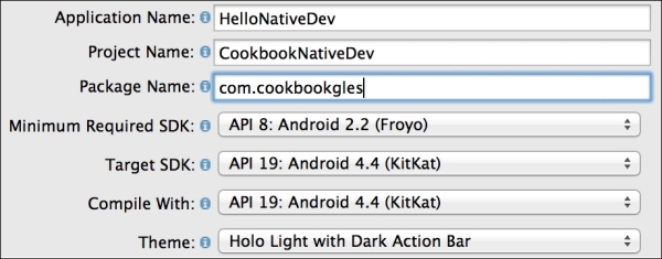
Accept the default settings and click on Next until the Create Activity page appears. Select Blank Activity from the given options and click on Next.
On the last Blank Activity page, change Activity Name to
NativeDevActivity, and click on Finish. This will create the project solution, as shown here:
The project solution contains various files and folders in it. Each of these has a specific role and responsibility, which is shown in the preceding image.
Go to
src|com.cookbookgles|NativeDevActivity.javaand replace the code with the following code snippet. Compile and execute the program. This will generate the necessary classes, which will be used by JNI:package com.cookbookgles; import android.os.Bundle; import android.widget.TextView; import android.app.Activity; public class NativeDevActivity extends Activity { static { //Comment #1 // "jniNativeDev.dll" in Windows. System.loadLibrary("jniNativeDev"); } //Comment #2 // Native method that returns a Java String // to be displayed on the TextView public native String getMessage(); @Override public void onCreate(Bundle savedInstanceState) { super.onCreate(savedInstanceState); //Comment #3 // Create a TextView widget. TextView textView = new TextView(this); //Comment #4 // Retrieve the text from native method // getMessage() and set as text to be displayed textView.setText(getMessage()); setContentView(textView); } }Add a new folder named
JNIin the project solution. This folder will contain all the C/C++ files. Create another new folderincludeinsideJNI. This will be used for header files. AddHelloCookbookJNI.handHelloCookbookJNI.cunderincludeandJNIfolders, respectively. Add the following code:HelloCookbookJNI.h:#ifndef _Included_com_cookbook_JNIActivity #define _Included_com_cookbook_JNIActivity #include <jni.h> JNIEXPORT jstring JNICALL Java_com_cookbookgles_ NativeDevActivity_getMessage(JNIEnv *, jobject); #endif
HelloCookbookJNI.c:#include "include/HelloCookbookJNI.h" JNIEXPORT jstring JNICALL Java_com_cookbookgles_ NativeDevActivity_getMessage(JNIEnv *env, jobject thisObj){ return (*env)->NewStringUTF(env, "Hello from Cookbook native code."); }
The JNI function syntax is as follows:
JNIEXPORT <return type> JNICALL <static function name> (JNIEnv *, jobject);
The function name under JNI contains the complete hierarchical path of the location where it is defined in the project. The rules are as follows:
The function name should be prefixed by
Java_Starting from the package name (
com.cookbookgles), each hierarchical folder and filename must be concatenatedEach concatenation must contain an underscore (
_) between two consecutive names
For example:
com.cookbookgles -> NativeDevActivity.java -> getMessage()
The name of the function will be defined as follows:
Java_com_cookbookgles_NativeDevActivity_getMessage
The full signature and name are given here:
JNIEXPORT jstring JNICALL Java_com_cookbookgles_NativeDevActivity_getMessage (JNIEnv *, jobject);
This process can be automated using the javah tool. For more information, refer to the There more … section):
Add
Android.mkunder JNI. Add the following code:// Android.mk LOCAL_PATH := $(call my-dir) include $(CLEAR_VARS) LOCAL_MODULE := JNINativeDev LOCAL_SRC_FILES := HelloCookbookJNI.c include $(BUILD_SHARED_LIBRARY)
The native code build process uses
Android.mkfor compilation of files. This makefile instructs the NDK compiler list of all the files that need to be compiled. It also maintains the order of files in which they need to be compiled.LOCAL_PATHis a predefined variable. It sets the path of the build system to the path of the current working directory. In other words, it is used to locate source files in the development tree It is specified with the current directory path using$(call my-dir).The
include $(CLEAR_VARS)helps the build system to remove any previous existing variables. It makes sure that no system or local variables are used from other modules. Such a multiple declaration of the same variable across different makefiles can confuse the build system. This command cleans all the local predefined variables, such asLOCAL_PATH,LOCAL_MODULE, andLOCAL_SRC_FILES.LOCAL_MODULEis a system variable that contains the name of the library exported by JNI. On successful compilation of the native code, JNI will generate a library with the name specified inLOCAL_MODULE. In the current recipe, it isJNINativeDev.so.LOCAL_SRC_FILEhelps the JNI compiler understand which files need to undergo compilation.include $(BUILD_SHARED_LIBRARY)helps the compiler build the library into a dynamic form (for example,.dllon Windows or.soon Linux). These libraries can also be built into static form usinginclude $(BUILD_STATIC_LIBRARY). This recipe uses the shared library.
Open a command-line terminal. Go to the current
JNIfolder path and executendk-build. This command, with the help ofAndroid.mk, compiles the source files and generates the shared library calledJNINativeDev.soin theCookbookNativeDev\libs\armeabifolder path: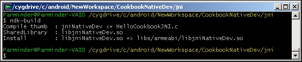
Inside
NativeDevActivity.java, you need to load the library before using it:System.loadLibrary("jniNativeDev");Connect your physical Android device to the system and execute the Android project with Ctrl + F11. This will display the following output on the screen. You can access the first example in the sample code folder
simpleJNI: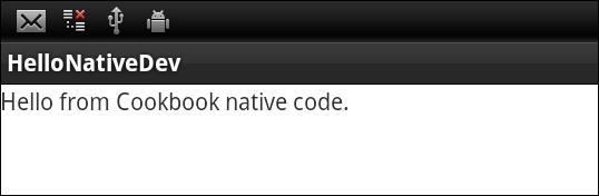
The regular Java code needs to know how to call the native C code. This is done by declaring functions in Java files where each function's signature is prefixed with a native keyword. The definition of these functions is defined in C/C++ source files. These functions need to redeclare in the header files, which must be located in the JNI folder. These declarations are in a special syntax rule that the ndk build understands. The functions are finally made available to Java in the form of shared or static libraries. You need to call this shared/static library within the Java code to use these exported functions.
In this recipe, you learned the convention to produce the JNI function's native method signatures. While working on large projects, sometimes, it is cumbersome to make such changes as the code could be significantly large. Additionally, the chances of human errors are also substantially high.
Alternately, the javah tool can be used to automate this process. It generates the C header and source files that are needed to implement native methods. It reads a Java class file and creates a C-language header file in the current working directory. The generated header and source files are used by C programs to reference an object's instance variables from the native source code. A detailed description of the usage of this tool is beyond the scope of this book. However, I highly recommend that you refer to the See also section for more information on this.
You can learn JNI programming (JNI specification) in detail from http://docs.oracle.com/javase/7/docs/technotes/guides/jni/spec/jniTOC.html
The javah tool reference is available at http://docs.oracle.com/javase/7/docs/technotes/tools/windows/javah.html
This recipe uses the NDK and JNI knowledge from the previous recipe to develop our first Android OpenGL ES 3.0 application. We will use our source code for NativeTemplate.h/NativeTemplate.cpp that we programmed in the Programming OpenGL ES 3.0 Hello World Triangle recipe. This recipe uses the Android framework to provide the necessary services to host the OpenGL ES program in it.
For our first Android OpenGL ES 3.0 recipe, we advise you to locate the sample AndroidHelloWorldTriangle recipe with this chapter. It will be helpful to import the contents to quickly build the application. To import recipes, refer to the Opening a sample project in Android ADT and iOS recipe in Appendix, Supplementary Information on OpenGL ES 3.0.
Here is the step-by-step procedure to program our first OpenGL ES 3.0 application in Android:
Create a blank activity project by going to New | Android Project. Provide a proper name for the application and project. For example, specify Application Name as
AndroidBlueTriangle, Project Name asAndroidBlueTriangle, and specify Package Name ascookbookgles. The package name in Java is equivalent to the namespace concept in C/C++.On the last page, specify Activity Name as
GLESActivity, Layout Name asactivity_gles, and Navigation Type asNone.In Package Explorer, browse to
AndroidBlueTriangle|src|cookbook.gles. Here, you will find ourGLESActivityclass. Under the same package calledcookbook.gles, add two new classes calledGLESViewandGLESNativeLib. In order to add a new class, right-click on thecookbookglespackage in the package explorer and go to New | Class.Use the sample recipe
AndroidBlueTriangleand copy/paste the contents ofGLESActivity.java,GLESView.java, andGLESNativeLib.javato the respective files of your project. In the next section, you will better understand these files and the classes contained in them.Add a new folder called JNI under this project. Inside this folder, create
Android.mk,Application.mk,NativeTemplate.h, andNativeTemplate.cpp. Theandroid.mknative code makefile is used by the JNI, as discussed in the previous recipe. UseHelloWorldAndroidto copy the contents of these two files from source to their respective files.For OpenGL ES 3.0,
Android.mkmust contain the-lEGLand-lGLESv3flags in order to link with the EGL and OpenGL ES 3.0 libraries. Also, as we target Android devices running Android version 18 (Jelly Bean), theApplicaton.mkmust contain theAPP_PLATFORM:=android-18platform.
Open the command-line terminal and run
ndk-buildinside thejnifolder. Under Eclipse, refresh Package Explorer so that the library created byndk-buildis updated in the project. Here is the rendering output upon execution: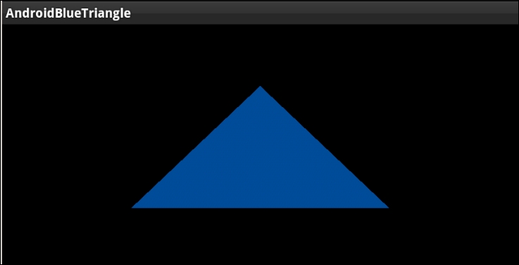
The first Android recipe for OpenGL ES 3.0 contains two OpenGL ES classes:
GLESActivityis an extended version of Activity. Activity is an application component that allows various types of views on the screen. Each activity has a window region, within which various type of views are rendered. For our requirements, we need a surface where we can render OpenGL ES. Therefore, theGLESActivityclass is usingGLESViewfor viewing purpose.GLESViewis our custom class that is extended fromGLSurfaceView. It provides a surface for OpenGL ES rendering. It helps OpenGL ES know about various events, such as the status of activity, whether it is in active or sleep mode, whether it has changed its dimensions, and so on.GLSurfaceViewprovides some important class interfaces. Among them, the three most important ones are as follows:GLSurfaceView.EGLConfigChooser: This class is responsible for choosing the correct EGL configuration, as per our requirements. Basically, an EGL is an interface between the OpenGL ES APIs and the rendering context. In order to use the correct rendering context, we should know the EGL configuration that suits our requirements. In this recipe, we have extendedConfigChooserfromGLSurfaceView.EGLconfigChooser.GLSurfaceView.EGLContextFactory: The rendering context is very much dependent on the device hardware configuration. OpenGL ES APIs do not know or care about creating the rendering context. Your local SDK provider is responsible for providing an interface to create it and attach it to your local application system. In Android, it is accomplished with theEGLContextFactoryclass. This requires EGL configuration. We have already seen how theEGLConfigChooserclass gave us the correct EGL configuration, as per our requirement. You need to use this configuration to create your customContextFactory, which is the extended version ofGLSurfaceView.EGLContextFactoryin our recipe.To create OpenGL ES 3.0 context, use the
eglCreateContextfunction. This function accepts an attribute list where the second item belongs to the OpenGL ES version, which must be 3.0. See the sample code give here for OpenGL ES 3.0 support:private static double glVersion = 3.0; int[] attrib_list = {EGL_CONTEXT_CLIENT_VERSION, (int) glVersion, EGL10.EGL_NONE }; EGLContext context = egl.eglCreateContext(display, eglConfig, EGL10.EGL_NO_CONTEXT, attrib_list);GLSurfaceView.Renderer: This provides the interface to manage OpenGL ES calls to render a frame. It calls the render function in loop.
NativeTemplate.cpp: This is the native code file that contains OpenGL ES commands responsible for rendering the blue triangle on screen.
When the Android OpenGL ES framework launches an activity, it first checks the available EGL configurations on device and chooses the one best suited to our requirements. This configuration is used to create OpenGL ES rendering context. Finally, rendering is performed by GLSurfaceRenderer, where it calls the native OpenGL ES code with the help of the GLESNativeLib class.
The OpenGL ES rendering source is coded in NativeTemplate.cpp, which is exposed to the Android framework via the libglNative.so static library. This library is compiled from the NDK using the ndk-build command and is automatically stored under the folder AndroidBlueTriangle | libs | armeabi | libglNative.so.
You can explore more about the official Android OpenGL ES and its framework classes at http://developer.android.com/reference/android/opengl/package-summary.html.
Refer to the Software requirements for OpenGL ES 3.0 – Android ADT recipe in Appendix, Supplementary Information on OpenGL ES 3.0
Using JNI on Android to communicate with C/C++
Development of OpenGL ES applications on iOS is much simpler compared to Android. The iOS 7 SDK, Xcode 5.0, and later versions support OpenGL ES 3.0. Using App Wizard in Xcode 5.0, the OpenGL ES 3.0 applications can be developed effortlessly.
Make sure that you should have iOS 7 support in your Xcode IDE. For more information, refer to the Software requirements for OpenGL ES 3.0 – Android ADT recipe in Appendix, Supplementary Information on OpenGL ES 3.0. It's advisable to import the sample recipe iOSHelloWorldTriangle in the Xcode. This will be helpful in understanding the theory quickly.
Here are the step-by-step descriptions of the first iOS OpenGL ES 3.0 application:
Open Xcode, go to File | New | Project, select OpenGL Game, and then click on Next.
Give Product Name, Organization Name, and Company Identifier as per your choice. For example, we are using
iOSBlueTriangle,macbook, andCookbook, respectively. Go to the Next page, select the location, and create project.Delete
ViewController.mfrom the project navigator. Instead, we will use our own file. Go to File | Add Files toiOSBlueTriangle. Now, locate the source code provided with this book and open theHelloWorldiOSfolder. SelectViewController.mm,NativeTemplate.cpp, andNativeTemplate.h, and add these into the project. Feel free to explore these added files. Build (command + B) and execute (command + R) the project.The development of OpenGL ES in Xcode makes sure that the correct version of OpenGL ES is used. It is automatically resolved by the Xcode build system using Deployment Target. If the deployment target is iOS 7, then OpenGL ES 3.0 libraries are used; otherwise, OpenGL ES 2.0 libraries are used. If the code in source files uses fixed function pipeline programming APIs, then it is understood that OpenGL ES 1.1 is used. For our current recipe, make sure you have set Deployment Target to 7.0:

The program handles reference counting by itself. Therefore, it is advised that you disable the automatic reference count (ARC) to build the program. Otherwise, the compilation may fail. Follow these steps to disable the ARC:
Click on you project in the organizer on the left-hand side
Select your target in the next column
Select the Build Settings tab at the top
Scroll down to Objective-C Automatic Reference Counting (it may be listed as
CLANG_ENABLE_OBJC_ARCunder the User-Defined settings group) and set it to NO
The Xcode provides an app wizard to the build the applications for iOS 7.0. The OpenGL ES development uses GLKit, which was introduced in iOS 5.0. The GLKit is an OpenGL ES development framework in objective C/C++. It is used to develop 3D graphics applications for programmable pipeline architecture. Since we are developing a portable application that works across platforms, this kit might not be fully helpful for us (GLKit is in Objective C/C++) in that direction. We will create our custom graphics development framework, which will be helpful for portable applications across Android and iOS. We will use GLKit to build the bridge between our graphics development framework kit and iOS. We will introduce this framework in Chapter 2, OpenGL ES 3.0 Essentials.
The app wizard creates two classes for us, AppDelegate and ViewController. These classes are described here:
AppDelegate: This class is inherited fromUIResponder<UIApplicationDelegate>, which defines the interfaces for aUIobjectthat respond to touch and motion events.UIApplicationandUIVieware also derived fromUIResponder. In iOS, theUIApplicationclass provides a centralized point of control to the underlying OS to coordinate with applications. EachUIApplicationmust implement some methods forUIApplicationDelegate, which provides the information on the key event happening with in an application. For example, such key events could be application launching, termination, memory status, and state transition.ViewController: GLKit provides a standardViewandControlleranalogy, throughGLKitViewandGLKitController.ViewControlleris derived fromGLKitController. Both classes work together to accomplish the rendering job.GLKitViewmanages the frame buffer object for the application. It takes the responsibility of rendering a draw command into the framebuffer when it is updated. However,GLKitControllerprovides the necessary interfaces to control the pace of frames and their rendering loop://AppDelegate.h #import <UIKit/UIKit.h> @class ViewController; @interface AppDelegate : UIResponder <UIApplicationDelegate> @property (strong, nonatomic) UIWindow *window; @property (strong, nonatomic) ViewController *viewController; @end
When iOS launches an application, it creates an instance of UIResponder, which basically creates the application object. This application object is a service for the application to provide a physical space in the screen window. This windowing is provided by the object of UIWindow, which will be created during the construction of UIApplication. This window object contains the desired view to display something on screen. In our case, this view should be some OpenGL rendering surface, which is provided by GLKitController to display. When the class object of GLKitController is created, it automatically creates the view associated with it. This helps the application to provide the necessary OpenGL rendering surface:
// AppDelegate.m
- (BOOL)application:(UIApplication *)application didFinishLaunchingWithOptions:(NSDictionary *)launchOptions
{
self.window = [[[UIWindow alloc] initWithFrame:[[UIScreen mainScreen]  bounds]] autorelease];
// Override point for customization after application launch.
self.viewController = [[[ViewController alloc] initWithNibName:@"ViewController" bundle:nil] autorelease];
self.window.rootViewController = self.viewController;
[self.window makeKeyAndVisible];
return YES;
}
The didFinishLaunchingWithOptions interface from UIApplicationDelete informs the event status of the application that it has completed loading. Within this event, we created the window and set the ViewController.
When a subclass from GLKitController is extended, it's very important that we override the viewDidLoad and viewDidUnload methods:
//  ViewController.mm
- (void)viewDidLoad
{
  [super viewDidLoad];

  self.context = [[[EAGLContext alloc] initWithAPI:kEAGLRenderingAPIOpenGLES3] autorelease];
  if (!self.context) {
    NSLog(@"Failed to create ES context");
  }

  GLKView *view = (GLKView *)self.view;
  view.context = self.context;
  view.drawableDepthFormat = GLKViewDrawableDepthFormat24;

  [self setupGL];
}
The viewDidLoad method helps create the rendering context and set up all its drawable properties for an appropriate configuration. To create an OpenGL ES 3.0 render context, we use initWithAPI. It accepts kEAGLRenderingAPIOpenGLES3 as an argument. This argument makes sure that the rendering context is meant for OpenGL ES 3.0 version.
We can modify the rendering context properties to configure the format of the drawable frame buffer object, such as drawableColorFormat, drawableDepthFormat, drawableStencilFormat and drawableMultisample.
This method is also a good place for initialization and other resource allocations. The last line is calling the setupGL function[self setupGL] in the objective C++ language syntax. Therefore, it is equivalent to this setupGL() in C++:
//  ViewController.mm
- (void)setupGL
{
  [EAGLContext setCurrentContext:self.context];
  GLint defaultFBO, defaultRBO;

  glGetIntegerv(GL_FRAMEBUFFER_BINDING &defaultFBO);
  glGetIntegerv(GL_RENDERBUFFER_BINDING, &defaultRBO);
  glBindFramebuffer( GL_FRAMEBUFFER, defaultFBO );
  glBindRenderbuffer( GL_RENDERBUFFER, defaultRBO );

  setupGraphics(self.view.bounds.size.width,
  self.view.bounds.size.height);

}
The setupGL function sets the current context with the one we created in viewDidApplication. This is very important to make the OpenGL ES APIs work. The glBindFramebuffer and glBindRenderbuffer APIs help the other APIs to know which target framebuffer to render on. In OpenGLES, the data is rendered in a rectangular array of information buffer container called a framebuffer. A framebuffer comprises many other helping buffers, such as color, depth, and stencil buffer, to accomplish rendering on the screen window. Sometimes, there could be cases where we may lose framebuffer or the render buffer. In such cases, it is advisable to bind these buffers with these two functions before you call any OpenGL ES3.0 API.
In order to render our application, we must override the drawRect method:
//  ViewController.mm
- (void)glkView:(GLKView *)view drawInRect:(CGRect)rect
{
    renderFrame();
}
The renderFrame function contains all the necessary code to render blue triangle.
Refer to the The fixed function and programmable pipeline architecture recipe in Appendix, Supplementary Information on OpenGL ES 3.0
Refer to the Software requirements for OpenGL ES 3.0 – iOS recipe in Appendix, Supplementary Information on OpenGL ES 3.0
Refer to the Building prototypes using the GLPI framework recipe, Chapter 2, OpenGL ES 3.0 Essentials

