Download code from GitHub
Exploring the M5Stack Core
You are the proud owner of a small and powerful microcontroller development platform called the M5Stack Core. The M5Stack Core uses the Espressif ESP32 microcontroller to allow you to create a variety of programmable electronic gadgets and devices. You can build programmable gadgets such as touchscreen controllers, Wi-Fi-operated devices, wearables, robots, and portable electronic games using the M5Stack Core. In addition, with the M5Stack Core, you can add visually appealing graphics and sound to your electronic creations easily and effectively using the Arduino Integrated Development Environment and the UiFlow Blockly code programming environment.
By the end of this chapter, you will understand the ESP32 microcontroller and the internal supporting electronics hardware. You will understand the M5GO Core hardware architecture’s inner workings. Finally, you will know about applying the internal support electronics hardware to create an interactive electronic widget device.
In this chapter, we’re going to cover the following main topics:
- Welcome to the M5Stack Core
- Overview of the M5Stack Core hardware architecture
- UI design basics
- UiFlow overview
- Communicating with the M5Stack Core
Technical requirements
To engage with the chapter’s learning content, you will need the M5GO IoT Starter Kit to explore the internal/external hardware electronics and software coding of your first basic application. The UiFlow code block software will be required to build and run the M5Stack Core application.
You will require the following:
- M5Burner
- The M5Stack Core
- The M5GO IoT Starter kit
- UiFlow Blockly code programming software
Here is the GitHub repository for supporting software resources: https://github.com/PacktPublishing/M5Stack-Electronic-Blueprints/tree/main/Chapter01.
Welcome to the M5Stack Core
In this section, you will learn the basic functions and features of the M5Stack Core. You will be able to perform the following tasks upon completing the lessons in this section:
- Power and reset the M5Stack Core
- Prepare the unit for programming
- Identify the three programmable user-interface buttons
- Identify the external ports for connecting electronic units
- Identify the USB port
- Identify the LED bars
- Select your stored applications
- Change the initial setup operation of the M5Stack Core
Upon completing this section, you will have a solid foundation of the external features and internal functions of the M55tack Core. Being able to complete these tasks will be important for programming and testing software applications that you create with your M5Stack Core. We will start the discussion with an overview of the M5Stack Core external features.
Powering and resetting the M5Stack Core
Turning on the M5Stack Core is quite easy to do. The M5Stack Core has a small red power button, as seen in Figure 1.1. The small red power button is located on the left side of the M5Stack Core. You turn on the M5Stack Core with a single press of the power button. You reset the M5Stack Core with a quick double press of the power button:

Figure 1.1 – The M5Stack Core power button location
Once the M5Stack Core is powered on, a UiFlow splash screen is displayed on the liquid crystal display (LCD), as seen in the following screenshot:
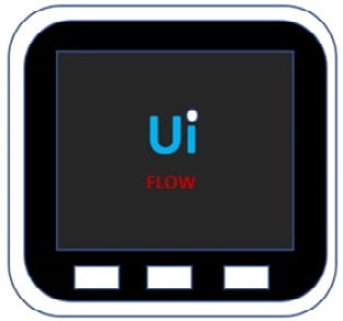
Figure 1.2 – UiFlow splash screen displayed after powering on the M5Stack Core
Initially, the M5Stack Core is programmed with 11 demonstration activities. The 11 demonstration activities are shown in the following diagram:
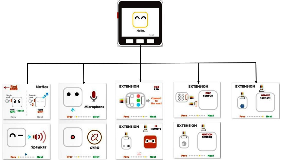
Figure 1.3 – UiFlow M5Stack Core demonstration activities
Next, let us learn about each demonstration activity through an accompanying explanation. We will explore the internal features of the M5Stack Core through a series of hands-on demonstrator activities:
- Demo 1 on/off: To turn off the M5Stack Core, a quick double press of the power button will accomplish this task, as seen here:
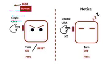
Figure 1.4 – The on/off operation of the M5Stack Core
- Demo 2 speaker: Press the center button on the M5Stack Core to hear a sound from the internal speaker:
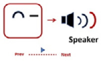
Figure 1.5 – Speaker demonstrator
- Demo 3 microphone: Speak into the pinhole microphone located on the side of the M5Stack Core. While speaking into the microphone, observe the line and sound wave images. Let’s see how this looks in the following figure:
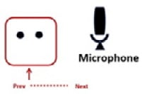
Figure 1.6 – Microphone demonstrator
- Demo 4 gyro: Tilt the M5Stack Core and observe the ball movement on the LCD screen. The movement is accomplished using a gyroscope and an accelerometer, as can be seen in Figure 1.7:
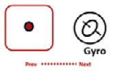
Figure 1.7 – Gyro demonstrator
- Demo 5 RGB LEDs: This demonstrator will glow and dim the sidebar RGB LEDs of the M5Stack Core. There is one LED bar on each side of the M5Stack Core:
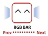
Figure 1.8 – RGB bar demonstrator
- Demo 6 ports explanation: The different electrical ports and their specific functions will be explored in this demonstration:
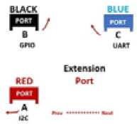
Figure 1.9 – Extension port demonstrator
Congratulations, you have completed exploring the internal features of the M5Stack Core. We will now learn about four sensor units from the M5GO IoT Starter Kit, which are shown in the following photo:
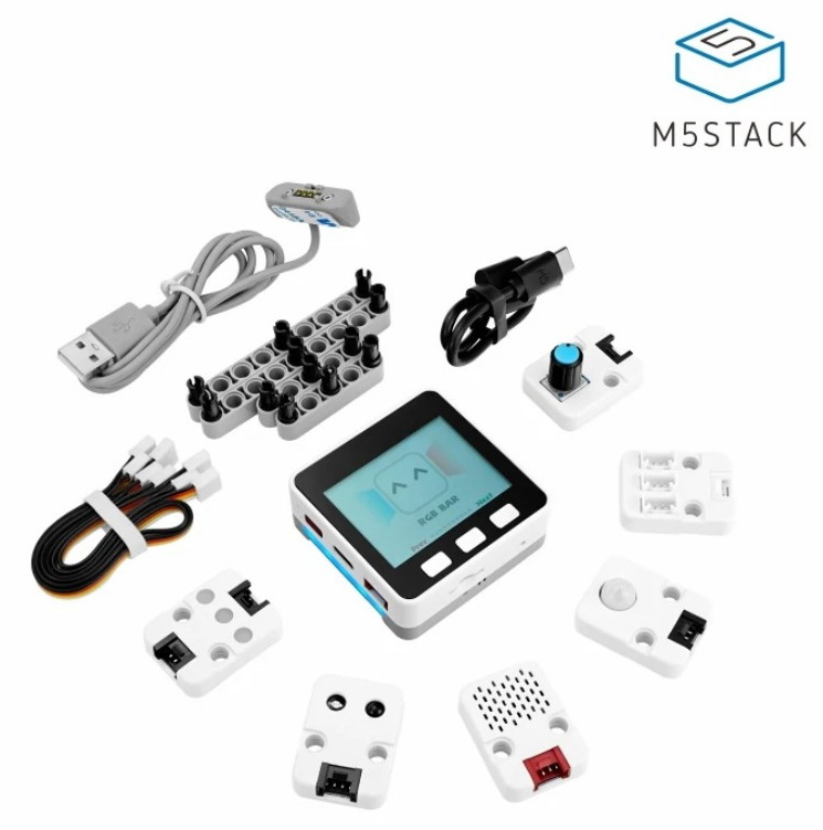
Figure 1.10 – The M5GO IoT Starter Kit
- Demo 7 environment sensor: The temperature and humidity levels are displayed on the LCD upon connecting the sensor to extension port A of the M5Stack Core:
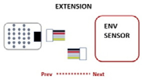
Figure 1.11 – Environment sensor demonstrator
- Demo 8 passive infrared (PIR) sensor: Attach the PIR sensor to extension port B of the M5Stack Core. You can observe a color change in the circle when placing your hand in front of the sensor. The color change response of the circle also occurs when you move your hand away from the PIR sensor. The following diagram illustrates the motion sensor’s response to a hand moved away from the PIR sensor:
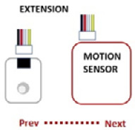
Figure 1.12 – PIR sensor demonstrator
- Demo 9 RGB unit: You explored the RGB LED bars in the fifth demonstrator activity. You will investigate the RGB LEDs packaged in this extension unit. This RGB LED unit will only light up when properly attached to extension port B. This diagram shows the wiring connector being attached to the RGB LED to connect to extension port B:

Figure 1.13 – RGB unit demonstrator
- Demo 10 infrared (IR) Remote unit: You can attach the IR Remote unit to extension port B using a wiring connector, as shown in Figure 1.14. Next, you take an ordinary IR handheld remote and point it toward the IR Remote unit. You can press any button on the IR handheld remote and observe the detection effect on the M5Stack Core LCD:
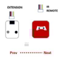
Figure 1.14 – IR Remote demonstrator
- Demo 11 angle sensor: You can test the knob on the angle sensor as shown in Figure 1.15, and observe the RGB LED bars getting brighter or dimmer:
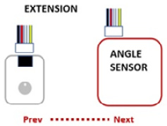
Figure 1.15 – Angle sensor demonstrator
Congratulations, you have learned about the M5Stack Core demonstrators. You have learned how to operate external sensors that are packaged with the M5GO IoT Starter Kit.
Note
To reinstall the firmware with the Demo app, use the M5Burner software. Select version 1.7.5 of the UIFLOW Core firmware. The name of the app is M5GO.py.
You have also learned how internal devices such as the RGB bar, microphone, and gyro operate using the appropriate M5Stack Core demonstrators. These mini hands-on demonstration activities allowed a glimpse into the M5Stack Core’s hardware architecture.
In the next section, we will dive deeper into the M5Stack Core’s hardware architecture by reviewing the electronic circuit schematic diagrams and the technical specifications of the ESP32-based programmable controller.
Overview of the M5Stack Core hardware architecture
In the previous section, you learned about the basic internal and external electronic features of the M5Stack Core. You investigated these basic features by using the M5Stack Demo app and specific IoT Starter Kit sensor units. In this section, you will learn about the embedded electronic subcircuits used to operate the M5Stack Core. The M5Stack Core’s hardware architecture consists of the following four electronic subcircuits:
- Power management
- Audio amplifier
- ESP32 subsystem
- USB-UART and accessories
The M5Stack Core hardware architecture system block diagram is illustrated in Figure 1.16:

Figure 1.16 – M5Stack Core hardware architecture system block diagram
EA3036 DC-DC converter (power management)
The EA3036 direct current to direct current (DC-DC) converter is a power management integrated circuit (IC). The EA3036 IC can be powered by one lithium-ion (Li-Ion) battery. The input voltage range for the EA3036 is 2.7 V (volt) DC to 5.5 V DC. The IC can also be powered by a basic 5 V DC adapter or phone charger. The EA3036 integrates three synchronous buck converters into one convenient 20-pin quad flat no-lead (QFN) IC package. Let us learn more about the EA3036 DC-DC converter by reviewing the IC’s physical pin packaging, shown in Figure 1.17, and the internal electronic circuits:

Figure 1.17 – EA3036 IC QFN package
The EA3036 DC-DC converter provides the 3.3 V (3V3) voltage source to operate the ESP32 microcontroller and support electronic circuit peripherals. Electronic circuit peripherals include the audio amplifier (N54148), A, B, C, and reset pushbutton switches, the LCD, the universal asynchronous receiver transmitter (CP2104) IC, and the USB-Micro (IP5306) circuit. The M5Stack Core Li-ion battery can power these subcircuits efficiently and effectively. The electronic circuit schematic and functional block diagrams for the EA3036 DC-DC converter are provided in the following diagram:

Figure 1.18 – The EA3036 DC-DC converter electronic circuit schematic and functional block diagrams
The EA3036 DC-DC converter can be used to source the appropriate voltage and current for the M5Stack Core’s N54148 power amplifier.
Power amplifier
As illustrated in Demo 2, the M5Stack Core has an audio power amplifier. The NS4148 is a 3-watt (W) class D audio power amplifier. The unique feature of the NS4148 is that the device can power down, which reduces power consumption. This feature allows the M5Stack Core to maximize its 3.3V Li-ion battery capacity. The NS4148 audio power amplifier can be packaged in an 8-pin micro-small outline package (MSOP) or a small outline package. To minimize the printed circuit board space of the M5Stack Core, the MSOP IC package is used. Figure 1.19 shows the MSOP of the NS4148 IC package:

Figure 1.19 – The NS4148 MSOP device
The electronic circuit schematic for the NS4148 MSOP-based 3 W Class D audio power amplifier is shown in Figure 1.20. Although the NS4148 is a low electromagnetic interference (EMI) filter-less IC device, there is a pair of inductor (L) and capacitor (C) (LC) filters on the audio output pins. The LC filters consisting of ferrite beads (FB1), FB2, and capacitors C42 and C45 are to remove the amplified audio signal ripple noise or waveform distortion from being emitted to the M5Stack Core’s speaker.
In addition, the bypass capacitor is connected across the collector supply voltage or voltage common collector (VCC) and ground (GND) pins to reduce high-frequency noise generated by the external clock circuit. The external clock circuit synchronizes the ESP32 microcontroller’s internal timing operations, such as the program counter. A variety of sounds can be created using MicroPython, UiFLOW, or Arduino C/C++ coding languages. The NS4148 audio power amplifier will amplify these sounds generated by the ESP32 microcontroller, allowing the unique tones to be heard through the wired speaker. The NS4148 receives the ESP32 code-based tones from the GPIO25 pin.

Figure 1.20 – The NS4148 3 W class D audio power amplifier circuit schematic diagram
ESP32 subsystem
The heart of the M5Stack Core is a 2.4 gigahertz (GHz) Wi-Fi and Bluetooth combination microcontroller. The ESP32 microcontroller is supported by 20 external components that enable features of the M5Stack to interact with the end user. The ESP32 provides appropriate control signals to the externally wired LCD and universal asynchronous receiver-transmitter (UART) devices. In addition, the A, B, C, and reset pushbutton switches are wired to the appropriate general-purpose input/output (GPIO) pins of the ESP32 microcontroller. The ESP32 microcontroller is packaged as a 48-pin QFN chip device. To ensure the proper timing of the ESP32’s core processor functions as the program counter or shifting data through memory register movements, an external crystal clock circuit of 40 megahertz (MHz) is used.

Figure 1.21 – ESP32 pinout and QFN48 package
The ESP32 microcontroller subsystem circuit schematic diagram is shown next:

Figure 1.22 – ESP32 subsystem circuit schematic diagram
An external 40 MHz crystal clock circuit, as seen in Figure 1.23, is used to maintain the proper timing and data storage operations of the ESP32 microcontroller’s core central processing unit (CPU):

Figure 1.23 - A 40 MHz crystal clock circuit
USB-UART and accessories
The method used to communicate internally and externally with the M5Stack Core uses a universal serial bus (USB) or UART circuits. The external port A allows units with inter-integrated circuit capabilities (I2C) to communicate with the ESP32 microcontroller. A serial clock (SCL) and a serial data address (SDA) scheme allow such units to share data with the microcontroller. In addition, sending application programs created using UiFLOW Blockly code, MicroPython, or C/C++ programming languages is accomplished with a data transmit/receive (TX/RX) UART scheme through a USB communication port. An IP5306 circuit is used to accomplish these communication tasks. The two USBs depicted in the circuit schematic diagram in Figure 1.24 represent the traditional data communication and extension A ports found on the M5Stack Core:

Figure 1.24 – The IP5306 USB-I2C communication circuit schematic diagram
Besides the internal circuits, the M5Stack Core uses a communication bus packaged on its bottom base to communicate with the microphone and the RGB LED bars. The communication bus allows the ESP32 microcontroller to receive and send audio and controls signals accordingly to the internal microphone and RGB LED bars. The allocated ESP32 GPIO pins are wired to the communication bus, thus allowing access to the audio and control signals from the externally connected devices. As shown in Figure 1.25, the GPIO15 pin operates the RGB LED bar. The ESP32’s GPIO34 pin is wired to the microphone and amplifier circuit:

Figure 1.25 – The M5 communication bus and associated peripheral devices
The following photo shows some of the ESP32 microcontroller supporting ICs, the microphone, the RGB LED bar, and the M5 bus:

Figure 1.26 – Location of the key electronic components and M5 communication bus
You now understand the M5Stack Core’s hardware architecture and the supporting electronic circuits. This knowledge will be important in the proceeding chapters of this book. The importance of this knowledge is in the development of interactive controls and wearable devices. In developing M5Stack Core projects, you will be immersed in the creative process of building practical and engaging products.
In the next section, you will learn how to design user interfaces (UIs) that allow interaction and engagement with the M5Stack Core.
UI design basics
In developing M5Stack Core applications, the UI aids in the operation of the device. The M5Stack Core’s LCD easily lays out graphics that convey information from electronic sensors attached to the programmable controller. The M5Stack Core LCD can also provide the status as output devices like an electromechanical relay. In this section, you will learn about effective visual effect approaches for UIs. You will learn about UI design basics that make your applications appealing and easy to use. Before you start designing your UI, the dimensions of the M5Stack Core are needed.
The M5Stack Core’s LCD dimensions are 320 x 230 pixels. Therefore, you have a total of 73,600 pixels available to create a variety of unique UIs:
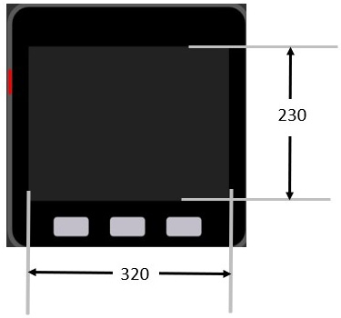
Figure 1.27 – M5Stack Core dimensions
The pixels are electronic dots arranged using a Cartesian coordinate system. When placing the images or controls, their locations can be managed using the Cartesian coordinate system. You can move the image quite easily using the UiFlow programming tool. The UiFlow programming tool has a design layout area that allows a preview of the images and controls placed on the LCD. The following example illustrates the x and y coordinates of 58 and 45 for the location of the square on the LCD:
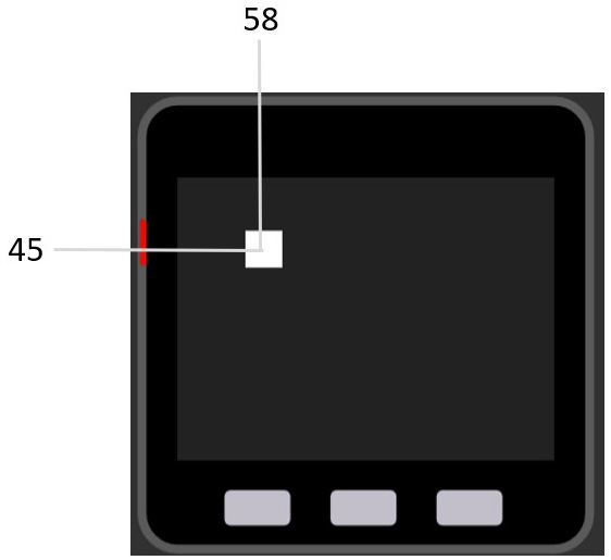
Figure 1.28 – Placement of an object on the UiFlow design layout area
The x-data point is 58 and the y-data point is 45. You can place the objects by dragging them to the specified location or entering them manually as follows:
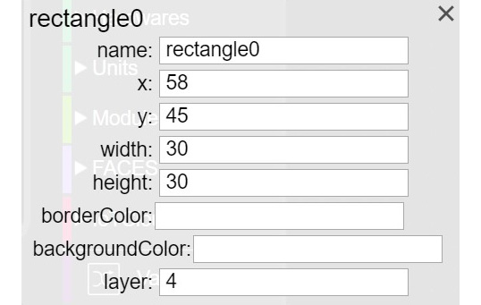
Figure 1.29 – Manual placement of a square on the UiFlow design layout area
You can obtain the properties box by clicking on the square. Once the properties box is visible on the UiFlow design layout area, x and y location data points may be entered as shown in the following figure:
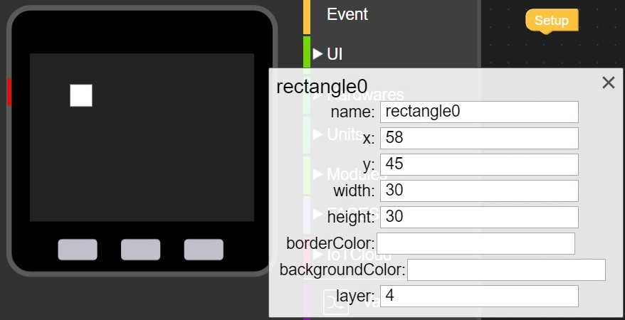
Figure 1.30 – Entering x and y data points into the properties box
The square can be precisely located on the LCD by entering the value incrementally in the properties box. As you enter the value, the square will move accordingly based on the coordinate position. You can use this approach to lay out your UI design on the M5Stack Core’s LCD. To make your UI effective, there are some basic design elements you need to consider.
Input controls
Input controls such as buttons, text fields, checkboxes, radio buttons, drop-down lists, list boxes, toggles, and date fields, allow the user to interact with your M5Stack Core device easily. You should size the input controls to be visible and for ease of use. Overlayed objects should not be placed on the input controls. Such information will make the input controls difficult to use.
Design considerations
When you lay out a UI design for an M5Stack Core device application, three factors should be considered: development, visibility, and acceptance. Let’s look at them in detail:
- Development factors: These help improve the visual communications of the UI design by providing tool kits, component libraries, and rapid prototyping support. The M5Stack Core’s main development factor is the availability of the UiFlow Blockly and Arduino code libraries. An example of a development factor is the Wi-Fi network UiFlow Blockly library shown in the following screenshot:
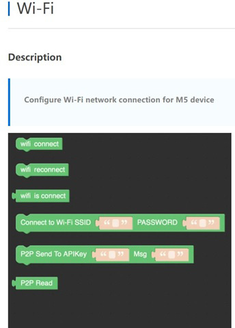
Figure 1.31 – Wi-Fi Blockly code library example of development factors
- Visibility factors: These allow multiple representations that aid the user to interact and engage with a UI design based on styles of learning and comprehension. Engagement, as it relates to the visual appeal of a UI design, provides education or is a productive tool and aligns with the learning aspect of the multiple representations concept. Examples of multiple representations include graphs, symbols, shapes, pictures, and sounds. The M5Stack Core includes a variety of shapes that will allow you to provide multiple representations for user interaction and engagement.
- Acceptance factors: These align with the documentation and training of the UI design-based product. For example, the M5Stack Core has been used in a variety of K-12 education classrooms based on the ease with which learners can create engaging and interactive devices. Figure 1.32 illustrates an acceptance factor using multiple representations for learner engagement and device interaction:

Figure 1.32 – M5Stack Core UI shapes for multiple representation
A final important note in designing and developing M5Stack Core UIs is simplicity. Simplicity is the design consideration consisting of using the important UI elements for communicating features and functions of your M5Stack Core device. The UI you design should be simple, eliminating unnecessary input control elements. The labeling of the multiple representations you use should be clear in language and messaging. The following screenshot illustrates clarity, thus eliminating unnecessary input control elements:
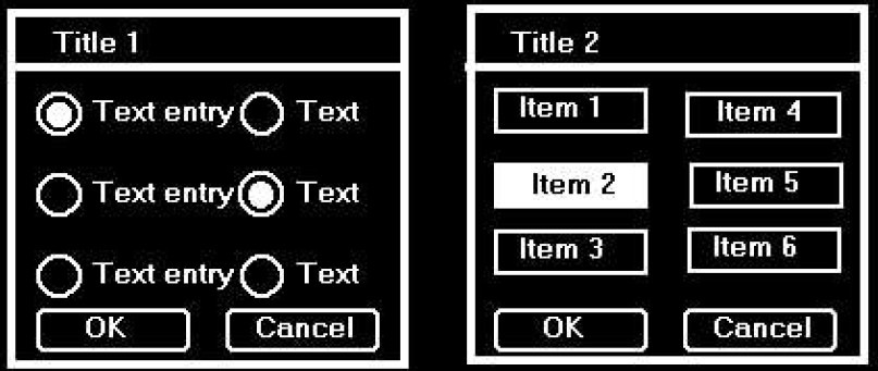
Figure 1.33 – (Left) complicated UI versus (right) simpler UI design
You now understand UI design basics that will aid in developing easy-to-use M5Stack Core applications. In the next section, we will present an overview of the UiFlow software.
UiFlow overview
In the previous section, you learned about some approaches to designing UIs to provide interaction for your M5Stack Core applications. The design basics provide suggested guidelines for developing uncluttered UI layouts. You can think of the design basics as the developmental theory to assist in creating UIs that have purposeful, engaging, and interactive functions for the M5Stack Core. In this section, you will learn about the UiFlow software basics. To start the learning journey, you will need to download UiFlow. You can use the following link to download the UiFlow software: https://shop.m5stack.com/pages/download.
Here’s what the page looks like:
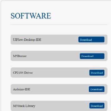
Figure 1.34 – M5Stack Core software
Download and install the UIFlow-Desktop-IDE (integrated development environment) software, as shown in Figure 1.34. Once the programming package has been installed, click on the icon to open the software, which looks like this:

Figure 1.35 – UiFlow icon
The UiFlow IDE will appear on your screen, as you can see in Figure 1.36. With the IDE open, various block categories, shapes, and an M5Stack Core preview will be visible. The UiFlow IDE will allow you to program the M5Stack Core using a variety of Blockly code blocks. You will construct your M5Stack Core application by stacking the Blockly code blocks and using shapes to create engaging product UI aesthetics and functions.
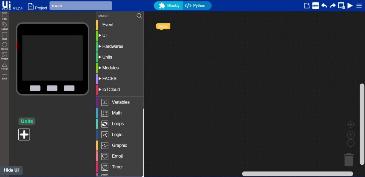
Figure 1.36 – UiFlow IDE
You will see that the UiFlow layout is very easy to understand and use. Figure 1.37 explains UiFlow’s IDE features. The M5Stack Core preview will allow you to design interactive devices to engage the end user with your product creation. To ensure your M5Stack Core device allows interaction and engagement with the intended product, you can consult the UI design basic material presented. A nice feature of the M5Stack Core preview is the ability to sketch out a UI design by using the shapes provided by the UiFlow software. You can proceed to design a UI that engages through simplicity and clarity.
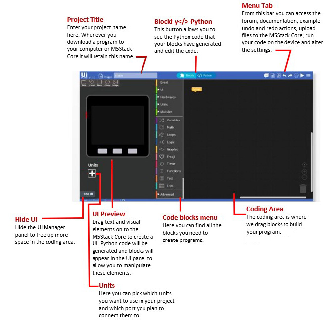
Figure 1.37 – UiFlow IDE layout explanation
With the UI design sketched out using the M5Stack Core preview, you can proceed to add function to the aesthetics by selecting appropriate Blockly code blocks. The UiFlow IDE provides several programming code blocks to provide interaction and engagement with your intended product. The software approach used to code is a top-down method. You can think about using Blockly code blocks in the same way as creating a functional flowchart. Instead of using pseudocode to capture the logic of the M5Stack Core’s function, the software algorithm development is created using Blockly code blocks. With the Blockly code blocks aligned with the UI design, you have now created an interactive device to engage your end user. There are several Blockly code categories to select within the coding development tool suite, as shown in the following screenshot:
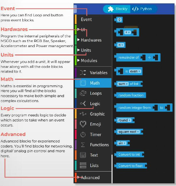
Figure 1.38 – UiFlow code blocks menu
You can develop a Blockly code program as a sequence of interlocking instructions. Each code block functional instruction feeds and interlocks with the next program block. Therefore, a mental model can be created whereby creating M5Stack Core product functions align with a sequence of a program diagram. You can use the following diagram to develop simple or complex functions for your M5Stack Core device. You can practice using this mental model diagram when creating your M5Stack Core device’s interactive function:
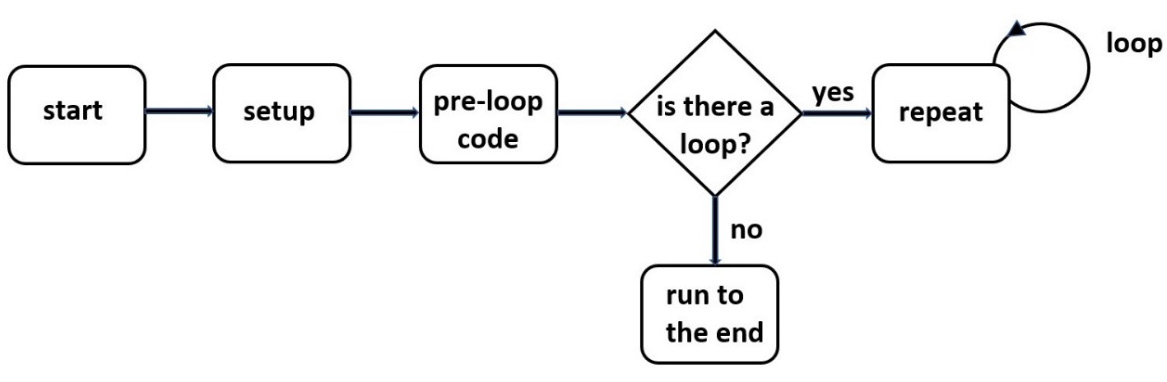
Figure 1.39 – UiFlow Blockly code program sequence diagram
Besides Blockly code block categories or menus, images, shapes, and the M5Stack Core preview, the menu tab plays an important role in the UiFlow software. The three basic Blockly code blocks that align with the program sequence diagram are Setup, Loop, and Wait, as shown in the following screenshot:
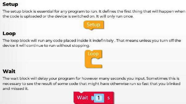
Figure 1.40 – UiFlow Blockly code program sequence diagram
You will use these three Blockly code blocks quite often to allow the M5Stack Core device application’s functions to be properly sequenced while maintaining engagement with the end user.
The role of the UiFlow menu tab is to provide you with a set of tools to run, test, and save your Blockly code. There is documentation on the code blocks and units for using them in your M5Stack Core device applications. Further, connecting to the M5Stack Core through USB can be achieved through the Setting menu. A description of the UiFlow Menu tab features is provided in Figure 1.41:
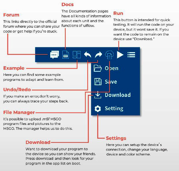
Figure 1.41 – UiFlow Blockly code program sequence diagram
The final section of this chapter will allow you to communicate with the M5Stack Core by establishing a proper communication setup with an ESP32-based device. You will use the UiFlow IDE software to communicate with the M5Stack Core device.
Communicating with the M5Stack Core
You are now familiar with the M5Stack Core’s hardware architecture, UI design basics, and UiFlow IDE. In this section, you will learn how to set up the UiFlow IDE to communicate with the M5Stack Core. Being able to communicate with the M5Stack Core is important because the Blockly code applications you design and implement will now be tangible devices that people can use for controlling physical objects, such as LEDs, motors, and buzzers. You will be able to sense objects and environments using PIR and temperature sensors. Therefore, running software for these hardware components is dependent on communicating with the M5Stack Core device.
Requirements
To engage with this section’s learning content, you will need the M5GO IoT Starter Kit to explore the internal/external hardware electronics and software coding of your first basic application. In addition, the UiFlow code block software will be required to build and run the M5Stack Core application.
You will require the following:
- The M5Stack Core controller
- The M5GO IoT Starter Kit
- UiFlow Blockly code software
Communication setup
The initial step to communicating with the M5Stack Core is to turn on the programmable device. Press the power ON button. Once the UiFlow splash screen is displayed, press the rightmost button on the M5Stack Core. The rightmost button is the M5Stack Core’s Setup function.
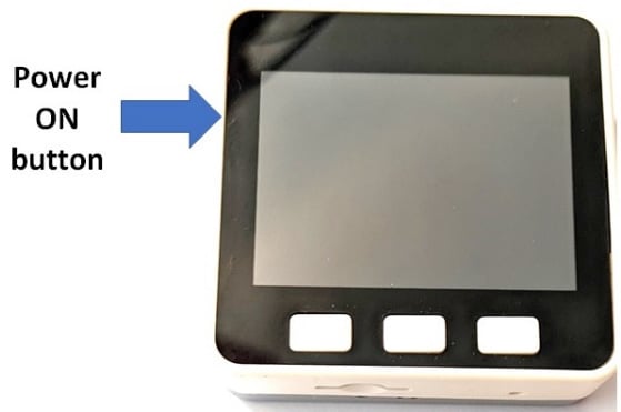
Figure 1.42 – Turning on the M5Stack Core
Then, perform the following steps:
- Scroll down to Switch mode.
- Scroll down to USB Mode. Use the middle button to select USB Mode.
These steps are shown in the following photo:
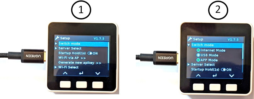
Figure 1.43 – Scroll to USB Mode
- Scroll down to reboot the M5Stack Core. Use the middle button to select the Reboot mode. After selecting Reboot, the USB API KEY splash screen will be displayed on the M5Stack Core unit’s LCD, as you can see in the following photo:
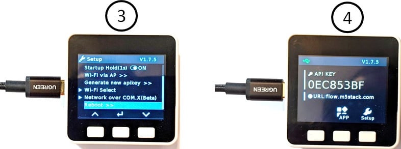
Figure 1.44 – Placing the M5Stack Core in USB mode (3 and 4)
You will then insert a USB-C cable into the M5Stack Core unit. Insert the other end of the USB-C cable into the development desktop personal workstation or laptop computer. Open the UiFlow Blockly code software. The Setting screen will appear on your personal desktop workstation or laptop screen. Select the M5Stack Core icon and the proper communication (COM) port, all of which you can see in the following screenshot:
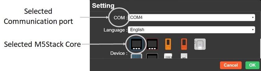
Figure 1.45 – Setting the communication port to select the M5Stack Core device
Once the M5Stack Core and communication port have been selected, click OK. The UiFlow IDE coding environment will be displayed on the screen as follows:
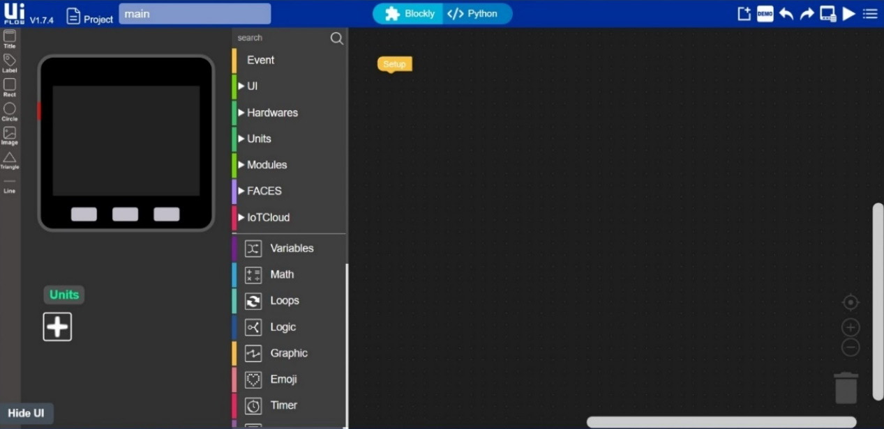
Figure 1.46 – UiFlow IDE
In the lower left-hand corner, you will see the Connected text displayed, as shown in the following screenshot:

Figure 1.47 – The M5Stack Core is connected to UiFlow Blockly code software
You will notice the COM4 port is displayed with the Connected text, which confirms that the selection for the communication port was correct. Congratulations, your M5Stack Core is now communicating with the UiFlow IDE! In Chapter 2, you will learn how to attach and program small electronic modules such as angle and motion sensors, an RGB (red, green, and blue) LED, and an IR Remote unit to the M5Stack Core. The knowledge you have obtained in this chapter will be used to explore M5Stack Units in Chapter 2.
Summary
In this introductory chapter, you learned about the technical skills of understanding the M5Stack Core hardware architecture. Within the M5Stack Core’s hardware architecture, you learned about the integrated circuits that provide the functional structure of this programmable device. You also covered how to operate the M5Stack Core demonstrators. Further, you learned about effective UI layout design approaches to make your M5Stack Core projects user-friendly. To implement the UI layout design approaches, you covered the UiFlow Blockly code features and functions that come as standard with the coding tool’s IDE. Finally, you learned how to set up USB communications between the UiFlow Blockly code IDE and the M5Stack Core.
With this knowledge, you will be able to explore the M5Stack Core units in the next chapter. The M5Stack Core units are small electronic modules that work with the hardware architecture and Blockly code discussed in this chapter. You learned about the electronic circuits that aid in the hardware architecture of the M5Stack Core.
In the next chapter, you will use this electronic circuits knowledge, the design layout approaches, and the UiFlow IDE to program the units in Blockly code to create engaging and interactive devices.