Download code from GitHub
An Introduction to IoT Architecture, Hardware, and Real-Life Applications
If you are a practitioner within the tech industry, the term Internet of Things (IoT) should not sound foreign to you. With the growing reliance of industries on the power of the internet, the web of IoT continues to expand. We now see it everywhere around us, even if we sometimes do not realize it.
IoT, through its various implementations such as real-time sensor data retrieval and automated task execution based on this data, plays a pivotal role in the development of smart cities. These systems, equipped with numerous sensors, take action when specific thresholds are exceeded, demonstrating IoT’s profound impact on our urban landscape, which is increasingly evident all around us.
In this chapter, we will explore IoT in your everyday life, how it contributes to the bigger picture of its ever-expanding ecosystem, and how to understand the architecture and hardware that make it up. As part of this, you will learn how to create simple systems diagrams for designing IoT architecture, build your own repository to store these solutions, and write code for a temperature sensor practical exercise. You will also be seeing the big picture of how component-based IoT is; that is, how small subsets of the architecture make up the larger implementations of it. These will be the foundational building blocks of designing industry-grade, complex systems, which we will build up in the later chapters of the book.
In this chapter, we will look to discuss the following main topics:
- What is IoT?
- Setting up the development environment of the book
- Choosing between IoT hardware
- Designing a simple IoT system diagram
- Defining systems and processes for smart objects
- Practical – creating a mini weather station
Technical requirements
Despite there being no technical requirements in particular, general knowledge of microcontrollers and networking technology would be helpful. As we will be working with microcontrollers, it would also be great to know some foundational C++. C++ is a powerful language that is used in many low-level environments, and it is an especially powerful language for building IoT systems. Because of this, the book’s hardware-based exercises are all based on C++. If you are not familiar with ++C, that’s alright, as we will explain what is happening in every part of the code and allow you to get familiarized with this language.
For this chapter, you can obtain all the code that will be used at https://github.com/PacktPublishing/IoT-Made-Easy-for-Beginners/tree/main/Chapter01. All code that is used throughout this book will be in their corresponding chapters within the IoT-Made-Easy-for-Beginners repository.
We recommend looking up any technical concepts that you do not understand, though we will keep it as foundational as possible to allow you to build up on the foundations from here.
What is IoT?
IoT, coined by computer scientist Kevin Ashton in 1999, is the term used to refer to the continuously growing network of physical objects that are connected to the internet, having them send and receive data. These objects vary from objects you find in your everyday life, such as smart fridges and mobile phones, to objects spanning entire industries or even cities, such as smart agriculture and smart cities.
Starting from just within your home, IoT has revolutionized how we live and interact with our environment. Some benefits of IoT within the household include the following:
- Increased convenience: Devices can be programmed and controlled remotely. For example, imagine adjusting your home’s lighting or heating using just your smartphone even when you’re miles away.
- Energy efficiency: Smart thermostats or lighting systems can optimize their operations based on your usage patterns, saving energy and cutting down on utility bills.
- Safety and security: IoT-enabled security systems and cameras can notify homeowners of potential breaches, and smart locks can grant or deny entry based on recognized users.
- Health monitoring: Smart wearables and devices can track health metrics and provide real-time feedback, potentially notifying users or medical professionals of concerning changes.
- Enhanced user experience: Devices can learn and adapt to users’ preferences, ensuring tailored and improved interactions over time.
Including the smart home, some vastly popular areas IoT has been implemented in can be seen in the following figure:

Figure 1.1 – Areas of use for IoT
As can be seen, the applications of IoT reach beyond just smart homes; they also assist with smart vehicles by facilitating GPS tracking and allowing you to upload images online from your smart camera. What makes this extremely powerful is that many actions that are put through this system can be automated through actuators. Actuators convert a control signal sent from the internet to perform certain motions, such as locking doors, turning off lights, and many more. These actions can be set to take place based on thresholds that are exceeded. For example, if the temperature of a room dips below 15°C, a user can use a smart thermostat and remotely schedule it to turn off the air conditioning until it reaches a temperature of at least 25°C, at which point it will turn on again.
The vision of the IoT
The original vision of the internet since the era of the World Wide Web (WWW) intends to focus on providing the convenience of searching for information and communicating with others. The widely held vision of the IoT, on the other hand, built up further from there and aims to be able to create a world where convenience of life can be granted in the form of having everyday things that are connected to the internet that in turn can communicate between themselves and with people, allowing for a vast number of capabilities. We have already seen this in a myriad of industries, particularly how it has helped reduce the manual labor that is needed to perform certain tasks.
IoT is often seen as a convergence of three different visions: the Internet Vision, the Things Vision, and the Semantic Vision. Each of these visions has its own part to play within the dynamic picture of the IoT.

Figure 1.2 – Visions of IoT
Things Vision
The Things Vision focuses on the technologies that are related to making things smarter; that is, those that can add capabilities to devices that allow them to communicated with the internet and with each other, alongside the data that they generate. The key aim here is to be able to gather and analyze data from a myriad of devices to gain insights and make better decisions. This is what has resulted in its evolution into smart sensor networks today.
Internet Vision
The Internet Vision focuses on the connectivity of the things that are connected to the internet and each other. The key aim of this vision is to be able to accelerate the ability and performance of the connectivity aspect as part of the IoT. As part of this, the storage and management of the data that has been gathered or generated is a key consideration, as it is important to understand the constraints, challenges, and opportunities of creating such solutions for the communication of the things. This was what led to the creation of many standards and communities, such as the open source Internet Protocol for Smart Object (IPSO) communities, which focus on finding solutions for smart sensor communication.
Semantic Vision
The Semantic Vision of IoT focuses on understanding the meaning of the data that is generated as part of the connected devices. It focuses on the challenge of interoperability; that is, how we can work with devices from different manufacturers and allow them to communicate with one another despite the different standards they may abide by. Interoperability is a big challenge within the industry, particularly with the different standards that many smart objects follow, and we are going to cover it in more depth in Chapter 8, Designing for Interoperability.
The evolution of the IoT
The concept of the IoT started with a lesser-known story based at Carnegie Mellon University in the 1980s, where a group of researchers developed a soda machine. The researchers wanted to track the content of the machine remotely, which led to them modifying the machine by installing a board that was able to obtain the status of indicator lights that show whether the sodas were currently stocked or empty. The status of each column within the soda machine was checked a few times per second. If a light went from off to on to off again in a matter of seconds, they would know that a Coke had been purchased. If the light stayed on for more than five seconds, it was assumed that the column was empty. With this kind of logic, alongside other indicators, they were able to create what the world regards as the first IoT-based machine.
Despite this, it was not until the 21st century that IoT really took off, powered by the development of low-cost and low-power consumption microelectromechanical systems (MEMS) sensors. This trend toward energy efficiency was crucial, especially as many IoT devices are battery-powered and need to operate efficiently for extended periods, so more hardware and software optimizations were made to conserve more energy. Another significant push came from the widespread adoption of internet-connected smartphones. The popularity of IoT further skyrocketed with the launch of the Raspberry Pi and the release of the IPv6 protocol, and now we have billions of IoT devices around the world. With technologies such as 5G and edge computing, it is only expected to grow further, as we can see how the performance capabilities of IoT networks only increase further with the new additions that are put forward by innovations.
Over time, there have been evolutions of concepts that have overlaps and may have been thought to be the same as IoT but are different. The next section presents comparisons to three main concepts: the web of things, machine-to-machine, and cyber-physical systems.
IoT versus the Web of Things
The Web of Things (WoT) is based on the connection and interoperability of smart devices through utilizing web standards and protocols. It aims to enable seamless communication and integration between a myriad of devices and systems without differentiating their underlying platforms. This usually uses web APIs to allow access for devices to interact with each other. IoT is about the connected devices themselves, but WoT is about the web infrastructure that allows the devices to interact and interoperate with each other over the web.
IoT versus machine-to-machine
Machine-to-machine (M2M) is based on the communication between two machines without the need for human intervention, which can be achieved through several technologies such as RFID or Bluetooth. IoT has a much wider range of applications compared to M2M, given that it is about the connection of an ecosystem of devices and systems, compared to the communication method of M2M, which is based on a closed system.
IoT versus cyber–physical systems
Cyber-physical systems (CPSs) are based on systems that integrate computational elements with physical components to allow for the capability of sensing, analyzing, and controlling physical processes. Such systems are intended to work in real time and are used in critical infrastructure such as emergency services, power grids, and transportation systems. Although they share common elements in the sense that they both use sensors and integrate computational and physical elements in powering actions to be taken, CPSs are usually more complex and pose more requirements based on the need for real-time performance and reliability.
The four pillars of IoT
There are four pillars of IoT that together form the IoT ecosystem, which ensures that devices can communicate with each other and other systems, enabling the generation of valuable data and insights.

Figure 1.3 – Four pillars of IoT
Let’s understand these pillars.
Device
The first pillar of IoT is device, which refers to anything around you, including phones, cars, and other electronic appliances, that can connect to the internet. With its dependence on the internet, it requires a wireless network or other connectivity solutions to allow it to continually transmit data to the internet and support the other pillars of IoT. Because of this, the question of where the data is to be stored temporarily if the device cannot connect to the internet should be considered when picking the appropriate devices.
Data
The second pillar of IoT is data, which is all about the information that is obtained by the connected devices as part of the IoT network. This data is then further analyzed and used for various purposes, including improving the deployed network, making decisions, and more. This is a pillar we will be seeing clearly throughout the exercises that we do in this book, as we will be referring to it to improve our data-gathering systems and make better decisions based on them.
Connectivity
The third pillar of IoT is connectivity, which is about the transmission of data and ensuring that all the pillars are connected. The importance of this pillar increases with the need for real-time data processing where no interruption to the connection to the internet is imperative, as missing data points could alter the interpretation of a system. For example, there could be data points that are gathered from a smart fire alarm system that signals that there is a fire, but if it is not connected to the internet, this may not go through and the actuators that would have been put in motion to alert the fire emergency services and sprinklers would not work, putting lives in danger. Because of this, considering the environment of your use case and the different edge cases that you may need for your deployment to work effectively is paramount to any IoT system that we are looking to build.
Analytics
The final pillar of IoT is analytics, which is all about analyzing the collected data, whether it be directly on the device, on an edge location such as a gateway, or on the cloud. It is a powerful step in the data collection process, as it is all about interpreting the data that we have obtained and understanding how it will impact our decisions. Some workloads may have simple analytical processes, such as simply generating charts based on the data that is obtained to summarize important insights, while others may go through more strenuous workloads, such as letting machine learning models analyze them on the cloud to derive more insights from them.
Important note
It is important to note that other books or standards may propose other pillars of IoT, though, in reality, most of them abide by the principles of the four pillars just mentioned, as it really is the functionality that is communicated by the pillars. In this book, we intend to provide the principles that are most universal around the IoT community, as just seen.
Now that you have a good idea of what IoT is about, we can move ahead and explore how we can set up the development environment for this book.
Setting up the development environment of the book
In this section, we will walk you through setting up the foundational development environment for the book. There may be additional configurations that will need to be done for specific chapters, but the setup here will be enough for you to make those additional ones with ease. The two main components that need to be set up here are the Arduino IDE for uploading code to your ESP32 microcontroller and your GitHub environment for source control. Note that ESP-32 is not part of the Arduino family hardware; we are simply using it as it is an editor that supports the development of ESP-32. We will also set up your AWS environment, but we will explore that in Chapter 7, Working with Cloud Computing to Power IoT Solutions where working with your workloads on AWS will be discussed further.
Setting up your Arduino IDE environment
Your Arduino IDE environment is where you will be working with your code and uploading that code onto your ESP32. Note that you are not limited to only using the Arduino IDE environment for doing this, so if you are familiar with other environments, feel free to use them. For the purposes of this book, we will be working with this IDE.
Arduino IDE environment
The Arduino integrated development environment (IDE) is a powerful, user-friendly software platform designed for programming and interacting with Arduino microcontroller boards. The IDE makes it easy for beginners to get started with microcontroller programming while also offering advanced features for experienced developers. In this section, we will guide you through the process of setting it up on your computer, enabling you to bring projects described in this book and beyond to life:
- Download the Arduino IDE environment at https://www.arduino.cc/en/software. Go through the installation process and accept the defaults, ensuring that you know where the program will be installed.
- Open your newly installed Arduino IDE. By default, we will not be able to find ESP32 as a supported board unless we specify it within our preferences. Go to File | Preferences. On the window that is opened, you should see a space for additional boards manager URLs. Enter the URL
https://raw.githubusercontent.com/espressif/arduino-esp32/gh-pages/package_esp32_index.json. Click OK. - Go to Tools | Board | Boards Manager and enter
esp32into the search bar. Click Install on the latest ESP32 version that pops up:
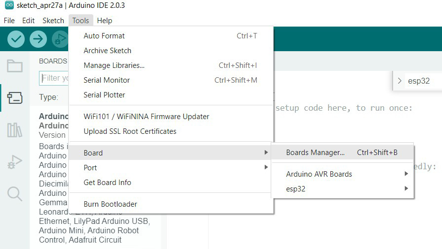
Figure 1.4 – Accessing Boards Manager on the Arduino IDE
- After installation, navigate to Tools | Board | esp32 and select NodeMCU-32S.
- We then need to install the driver for the ESP32. To check which type you are using, navigate to Device Manager on your device by searching it up on the Windows Start menu and expanding the Ports (COM & LPT) dropdown. Take note of the COM port that is being used; we will also need to set our Arduino accordingly to that later. If the same type is used, which will require the CP210x driver, you will be able to download it at https://www.silabs.com/developers/usb-to-uart-bridge-vcp-drivers?tab=downloads.
- On the Arduino IDE, navigate to Tools | Port and select the COM port that is being used.
- Attach your ESP32 to your laptop using a mini USB.
- Click File | New Sketch in the top-left corner of the program.
- You will see the following code in your environment:
void setup() {
  // put your setup code here, to run once:
}
void loop() {
  // put your main code here, to run repeatedly:
}
To see whether your IDE is working correctly, click on Verify, which is the button in the top-left corner of the screen.
- To see whether your device is configured correctly, click on Upload, which is the second button from the left. While the upload is, hold down the Boot button, which is the button in the bottom right.
Check your IDE’s terminal to see whether the code has been uploaded successfully.
With this, your Arduino IDE should be set up and ready to be used. We can now proceed to try it out with our inaugural Hello World exercise.
Red LED Lighting Hello World exercise
To test the functionality of the ESP32 and to give you a taste of working with your new development kit, we are going to create the equivalent of a Hello World exercise—a practical exercise to light up a red LED bulb.
Components you’ll need
For this, you will need the following components:
- An ESP32 microcontroller
- A red LED (or any other color you would like to use)
- An 830-hole breadboard
- Two jumper wires
- A 1k Ohm resistor
As you go along, you can refer to the upcoming assembly diagram to see the placement of the components on the board and get an overall idea of what we are trying to create to follow the instructions more easily.
Setting up the required hardware
Now, we will proceed to set up the hardware accordingly. The following figure shows the breadboard diagram that can be used as a reference while you follow the instructions to wire up the board, breadboard, LED, and resistor:
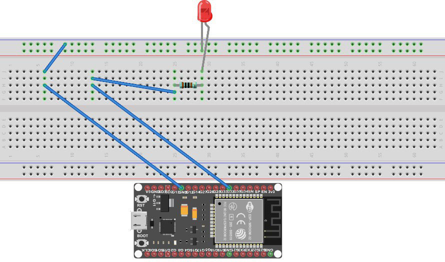
Figure 1.5 – Breadboard diagram for connecting the LED
- The long leg of the LED is the anode and the shorter leg is the cathode. Attach the anode to hole 30j and the cathode to hole 30- on the breadboard.
- We now will attach the ESP32 to the board. Attach the ground pin (GND on the board) as shown in the figure to hole 6h and 3g to hole 13h. You can either do this with a jumper cable or just directly put it down with the corresponding legs of the microcontroller as such.
- Attach the 1k Ohm resistor with one leg on hole 30h and the other on hole 25h.
- Attach a wire from hole 25g to hole 13i.
- Attach a wire from hole 6j to 9-.
Now we have successfully set up the hardware that is needed for this practical exercise. We can now move on to producing the necessary code on our Arduino IDE.
Coding it up on the Arduino IDE
Now, we will upload the code for running the LED experiment to the ESP32. Use the following code for this purpose:
const byte led_gpio = 32;
void setup() {
  pinMode(led_gpio, OUTPUT);
}
void loop() {
  digitalWrite(led_gpio, HIGH);
  delay(1000);
  digitalWrite(led_gpio, LOW);
  delay(1000);
}
In the setup section of the code, the digital pin led_gpio is initialized as an output. Within the loop section of the code, we are simply alternating between turning the light on and off (as indicated by the high and low). Each wait 1,000 milliseconds—equivalent to one second—before switching to the next state, as seen with the delay statement.
And with that, you’ve just created your first IoT program on the ESP32!
Setting up your GitHub repository
GitHub is a code repository platform that is used for version control and collaboration on your code. With it, developers can track changes to code and collaborate on a project, while also setting extra restrictions for changes as part of best practices such as letting developers review each other’s code and merge changes from anywhere. We will be using GitHub throughout this book for you to both use the platform to pull the code that we use throughout our chapters and put in your code.
Setting up your GitHub account
To start, we will create our GitHub account to use to set up our repository:
- Navigate to https://github.com/ and click on the Sign Up button in the top right.
- Enter your email, password, and username as prompted. Check your email for verification and log in to GitHub.
You now have a GitHub account, which is the first step for setting up our version control environment and for making optimum use of the resources of this book that are ready for you to pull onto your local environment.
Setting up your GitHub CLI
When you pull code or create local repositories to push up to GitHub, it is much easier if you use the command-line interface (CLI). The following are the steps that you need to take to install the CLI on your laptop:
- Assuming you are on Windows, you will need to go to https://github.com/cli/cli/releases. Navigate to the latest release (at the time of the writing of the book, it is
2.21.1, but this may change, so navigate accordingly) and download the file that ends withwindows_amd64.msi. - Follow through with the default installation prompt and install the CLI in a location of your choice.
- In the case that it is not done by default, open your Windows Start Menu, go to Control Panel | System | Advanced System Settings | Environmental Variables, and click Edit on the
Pathvariable within the user variables for your account. Click New and add the path of the folder that contains your GitHub installation. - Check whether your CLI has been installed successfully by opening your command prompt and typing
git –version. If the output returns the version, that confirms that Git is already installed. - You will now have to set your GitHub credentials. Configure your username to record changes you make to your local repository with the command as follows:
$ git config –global user.name "{firstname} {lastname}" - Configure an email address that will be associated with each of your history markers:
$ git config –global user.email "{youremail}" - You now need to authorize your device to modify repositories that are owned by your GitHub account. As part of this, we need to register an SSH key. Start by generating an SSH key via the command prompt with the following command:
$ ssh-keygen -t ed25519 -C "{youremailhere} - When prompted, specify the folder to generate the SSH key to; otherwise, let the default be and change the directory into the folder that it is generated in.
- Open the
id_ed25519file that is generated in a text editor of your choice and copy the contents of the file. - In GitHub, in the top-right corner, click your profile photo and click Settings.
- In the
Accesssection, click on the SSH and GPG keys. - Click New SSH Key or Add SSH Key.
- In the
Titlefield, add a label that describes the purpose of your key, such as an identifying name for the device you are linking it with. Select the type of key, which in this case is Authentication Key. Paste the key that you have copied into the Key field and click the SSH key.
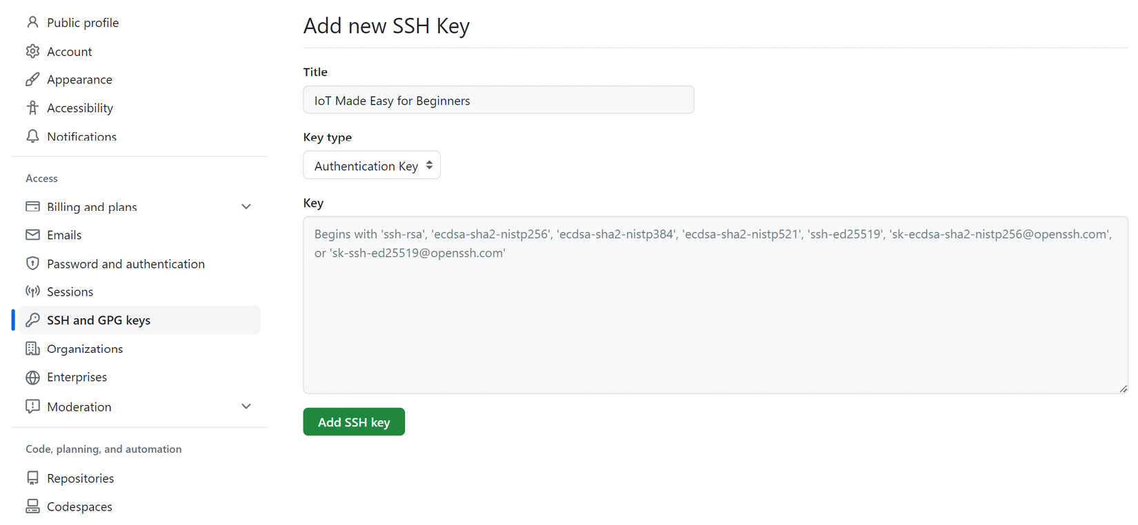
Figure 1.6 – GitHub page to add a new SSH key
You should now have authorized your device to modify repositories on GitHub, so we will now be able to push code from our local development environment onto the GitHub repositories.
Pulling your code from a repository
If your CLI is configured properly, you should be able to pull the code from the repository straight to your local development environment:
- Navigate to the repository from which you would like to pull your code.
- Click on Code and click SSH.
- Copy the SSH line that is noted there. Ensure that your command line is currently open in the folder that you want the repository to be cloned into. Run the following command on it:
$ git clone {SSHLine} - Your repository should now be in the form of a folder; you just need to change the directory into that new folder.
Creating a GitHub repository for your code
Your GitHub repository is where you will be storing, committing, and pushing your code. You will need to create one via GitHub to then push and pull to and from your local development environment:
- On your GitHub home page, click on New repository.
- Type a name for your repository and add a description of it.
- Choose the visibility of your repository. Unless you want to prevent your repository from being accessed publicly, select Private.
- Select Initialize this repository with a README to continually update your repository with a summary.
- Select Create Repository.
You should now be able to push to the repository as part of the next section.
Initializing, committing, staging, and pushing – oh my!
These four steps are a crucial part of any GitHub experience, as you want to store the code and continually update the repository based on the changes you have done to collaborate with others or simply just to track the changes that you have made as part of the version control process.
To understand how these four steps work for your projects, let’s go through them:
- To initialize a folder as a Git development folder, type in the following and a
.gitfolder should be initialized in your folder:$ git init
- You next need to add the files in your local repository to be staged. We use a dot to add all files; otherwise, we specify which file(s) we would like to add:
$ git add .
- We then commit the files that have been staged in the local repository, adding a commit message:
$ git commit -m "{Your commit message here}" - We then specify the URL for the remote repository that we intend to push the code toward:
$ git remote add origin {remoteURL} - We then verify that it was successfully added by running the verify command:
$ git remote -v
- We then push the changes we have already staged to our repository:
$ git push origin main
Note that if the folder is already initialized as a local repository and the remote URL is already set, we will only have to repeat steps 2, 3, and 6 for every consecutive push.
Testing it for your newly created Hello World LED project
Now that we have the skills for GitHub, let’s use it to push your newly created Hello World LED project’s code into GitHub:
- Create a repository on GitHub as per the instructions just given for creating a new repository.
- On your command prompt, navigate to the folder containing your project code. Run
git initto initialize the folder as a repository:$ git init
- Add all files in the folder to be staged:
$ git add .
- Enter a commit message that makes sense for adding this deployment. In this case, it might be something as simple as this:
$ git commit -m "Created Hello World LED IoT Project"
- Navigate to your repository page on GitHub and copy the HTTPS URL on the project. Paste it within the command to add the origin for the project:
git remote add origin https://github.com/renaldig/firstledproject.git
- Push the changes you already have staged to the repository:
$ git push origin main
And with that, you have your first repository good to go! Try to practice making a few changes to your code and repeating the process. See whether you can answer the following questions:
- How can I revert to a previous version of my code?
- What types of branches would I need to create for an industry-based IoT project?
With this, you should now be able to use the Arduino IDE, try out a practical exercise that demonstrates the capabilities of Arduino at a high level, and create and use GitHub in your local environment for version control. In the next section, we will explore how we can choose between IoT hardware, considering the unique set of requirements that projects need.
Choosing between IoT hardware
Choosing optimal hardware for an IoT project is imperative, especially when it comes to creating industry-grade implementations. Related hardware and software for IoT go through a standardized design process: requirements specification, conceptual design, prototyping, testing, and finally the rollout of the hardware and software that are part of the system. Some platforms, such as ESP8266 microcontrollers, facilitate easy prototyping and deployment, but this convenience often comes at the expense of lower processing power when compared to other options.
There are many factors to consider, but they can be categorized into four different factors: data acquisition, data processing, connectivity, and power management.
Data acquisition
Data acquisition is a major part of IoT systems, as many components of a system, in the form of sensors, function to collect data in the environment to provide real-time results and/or feedback. This data is often obtained at a fixed rate within a time known as the data sample rate and transmitted to a remote output device to be read in and sent for further processing.
Sensors are devices within an IoT network that are used to detect and measure physical quantities such as humidity, pressure, speed, light, and temperature. This data is obtained from the environment and sent through to the IoT platform either wired or wirelessly.
The way we interact with sensors also differs from use case to use case. As an example, instead of monitoring the environment, some sensors may instead monitor its internal state; these are known as proprioceptive sensors. There can also be sensors that allow personnel to interact directly with them via buttons or touchscreens while recording the actions that are done; these are known as-machine interfaces.
When evaluating which sensor to use, multiple factors come into play. The first and most obvious one is functionality. What are you going to use the sensor for? If you are going to measure changes in the environment for temperature and humidity, for example, you would consider the DHT11, which is a temperature and humidity sensor developed by Adafruit. It comes standardized in many development kits, including the one that this book uses. However, just because you have obtained a sensor that does what you need it to do does not mean that you have found the optimal sensor.
There are many options that need to be considered that are offered by sensors, which is why comparing sensors by their specifications is very important. The condition in which the sensor can operate is another important consideration. Where will you use it? Will it be used at room temperature or in extremely hot or cold environments?
The next consideration is the accuracy and precision of the sensor. Precision is the repeatability or consistency of the measurement. With high precision, a sensor will be able to produce results that deviate very slightly from one another when the same measurement is taken multiple times with the same conditions put on it. On the other hand, with low precision, a sensor would produce results that would deviate more from each other despite the same conditions put on it. This often comes as a trade-off with accuracy, which is how close the measured value is to the actual value of the physical quantity that is being measured. High accuracy for a sensor can produce results that are very close to the actual value, while low accuracy for sensors outputs results that deviate further from the true value. It is important to understand that a sensor can be precise but not accurate and vice versa. Optimally, we would like the sensor to be both precise and accurate, but there are often trade-offs between the two.
Finally, we must consider the resolution of the sensors. The resolution determines the smallest change within the physical quantity that the sensor is capable of detecting. For example, if a temperature sensor has a resolution of 0.1°C, this means that the sensor can detect changes in temperature as granular as 0.1°C. Hence, higher resolutions for sensors allow them to detect smaller changes within the physical quantity, while lower resolutions are only able to detect larger changes. It is also important to note that other factors aside from the sensor may also affect the resolution, such as the accuracy of the analog-to-digital converter (ADC), which converts the sensor’s output to digital form, and the accuracy of the software that processes the data sent by the sensor, which affects the overall resolution of the measurement system.
For example, we can compare the DHT11 and DHT22 sensors that are both developed by Adafruit. The following are the specifications for them from the Adafruit website:

Figure 1.7 – Comparison of DHT11 and DHT22 sensors from Adafruit
At first glance, they both provide the functionality of being able to measure temperature and humidity, but they both have different specifications that can meet your deployments’ needs differently. When comparing the specifications, we can see that despite there being many factors that are the same between them, each has its own set of advantages. The DHT11 has a lower cost and a better resolution compared to the DHT22, while the latter has higher accuracy and works over a larger temperature range than the former. Depending on our priorities, this will affect how we choose one sensor over another with these specifications.
These sensors then lead to the next part of the consideration of hardware for the architecture, which is within data processing.
Data processing and storage
Data processing and storage is a crucial part of working with data as part of the IoT. Once we have obtained the data, we must determine how we can analyze, interpret, and work with the data. In different use cases, data is processed in different places of the architecture; the device obtaining the data may process the data itself while in other use cases, it may transmit the data to other places first, such as gateway devices or cloud applications, for the purpose of conducting further analysis.
The processing power and storage size that an IoT application needs rely on the performance needed by the consumers of the data; consumers may use different services of applications that utilize the data either for further processing or as an end goal. These may include factors such as memory, number of cores, clock speed, or processor specifications; all determine the device’s capability for data processing.
Two distinct scenarios arise when considering where to process and store the data:
- Battery-powered devices: Consider a simple device such as a temperature sensor powered by batteries. Such dummy devices aren’t typically designed for local data processing and storage. The simpler the design, the lower the power consumption and, subsequently, costs.
- Externally powered devices: Devices with an external power source, such as machines or electricity meters, can afford to have local data processing and storage. This arrangement not only reduces service latency but also conserves wireless backhaul bandwidth, enhancing the overall efficiency.
On the capacity side, this is what makes the consideration of non-volatile memory—the temporary data storage before data is transmitted upstream—imperative; we want to account for being able to hold data while considering the different environments that the device may be in. Is the data in environments of intermittent internet connectivity meaning there may be a chance of data loss if it relies fully on the internet to continuously store data in an upstream provider? Do we do data processing within the device itself? These are all questions that we need to consider when carefully choosing the hardware we need.
Connectivity
Connectivity to networks is a crucial element of IoT devices. There are different types of connectivity to consider. It may be wired or wireless, depending on its use case. Wired communication is usually used for stationary devices and connected via the Ethernet, such as with smart buildings or home automation. On the other hand, wireless communication includes technologies such as Wi-Fi, Bluetooth, WAN technologies (such as LoRa), NB-IoT, and cellular networks. Don’t worry if you don’t know these terms; we’ll talk more about them in the upcoming chapters and ensure that you have a thorough understanding of them and how to make the best use of them depending on your individual use case!
In connecting such devices together over a network, there are two main methods of communication: serial and parallel. With serial communication, data is transmitted one bit at a time over a singular communication line. Serial communication is usually used when the distance that the communication must be based on is relatively long or when the data rate is relatively low. Furthermore, it is used when there are a limited number of available communication lines or when the complexity of the system needs to be minimized. It uses protocols such as the RS-232 or the RS-422 protocols. Some examples of when serial communication would be used are as follows:
- Communication between a microcontroller and a sensor
- When two computers are located at a long distance from one another
In parallel communication, multiple bits are transmitted at the same time through multiple communication lines. It is normally used when the communication distance is short and the data rate is high. Furthermore, it is often seen in systems where the number of bits that are transmitted simultaneously is huge. It includes protocols such as IEEE, 1284, and PCI. Some examples of parallel communication’s uses are as follows:
- Communication between two computers that need to exchange large amounts of data quickly
- Communication between a computer and a printer
We will cover connectivity in more detail in Chapter 4, Examining Communication and Connectivity Technologies, when we talk about connectivity and communication solutions.
Power management
Power management is a critical consideration within any IoT network. This is particularly true for devices that rely on a wireless power source, which usually depends on batteries or solar cells. There are mainly three main power consumption factors: the sensor, the microcontroller unit, and the wireless backhaul. Aspects that we need to consider include the cost, performance, and battery life of a device. There are multiple approaches that are often used to manage this effectively:
- Cloud computing: Letting the cloud handle processing and storage is often a great solution for reducing the power consumption of the device, as it will allow it to process data minimally when communicating with the cloud or to simply just perform its data collection when needed and sleep when it is not required for usage at a particular moment.
- Sleep modes: Microcontrollers and other types of hardware can often enter a sleep mode when there’s low power consumption. It often is up to the user to configure the device to sleep and wake at certain times, which necessitates them to know the periods of high consumption and low consumption or simply to set a threshold and let the device detect on its own. This often reduces power consumption significantly.
- Power-efficient hardware: Using power-efficient hardware is a very important consideration and may be why some pick one microcontroller over another. This factor is listed on the specifications of the microcontroller, sensor, or other peripherals, as choosing such efficient devices would minimize costs, especially when working with a network filled with them. However, this may come with performance trade-offs, which is why it is important to look at all the specifications carefully to see whether the trade-offs are ones you can afford to make and consider what you really would like to prioritize.
- Power management integrated circuits (PMICs): PMICs are chips that are used to manage the power consumption of a device. They are used to regulate the power supply to various components within the system, ensuring that only the portion that is allocated to the components gets through. This can be a powerful tool to regulate your system.
- Energy harvesting: Some energy harvesting methods, such as solar panels, are also effective ways of making use of power in a natural and cost-effective way. This would help you extend the device’s battery life while also reducing the need to purchase batteries. However, this would depend on the environment of the device, as not all environments are conducive to this practice. For instance, not all areas have constant sunlight; solar panels would not work in these cases, and alternative means must be considered.
As can be seen from this section, all of the outlined factors depend on one another. This also leads to certain trade-offs, as it is often not possible to find the ideal device that can satisfy all four factors perfectly while still saving costs. It all depends on what your use case is and to what extent you would like your IoT system to meet it.
With this, you will have understood much more about selecting IoT hardware. As can be seen, sometimes some decisions are not as easily made when there are important trade-offs to consider, but it is often important to prioritize what you want to get out of it instead of trying to achieve the best of everything. In the next section, we will discuss how we can start designing simple IoT system diagrams.
Designing a simple IoT system diagram
Designing an IoT diagram is a skill that you will need to pick up and get familiar with when working with system/network deployments, especially in designing and presenting industry-grade solutions within the industry, as you will be architecting solutions and showing your thought processes behind certain design choices. The technical depth of your design will also differ from user to user. For example, a CIO might not care that much about the full list of services that you use on AWS to ingest, process, and analyze data that you have obtained on your sensor and have sent to be processed; rather, they would just like to see how it works overall. The technical depth may be more suited for an engineering manager or another developer on the team to help them better understand the design choices that are being proposed and why certain choices have been made. This will also serve as a reference for you to go back to when considering which parts of the architecture you can revise in the future.
In this section, we will start by looking at two high-level design flows: one for the flow of a smart lightbulb’s communication with a user interface and one for a design flow that is based on AWS. In the following chapters, we will be discussing how to create more complex diagrams, so this will help you get used to how these flows can be represented and what the best practices are to make them presentable to your target audience.
A high-level design flow for a smart lightbulb
In this diagram, we can see the design flow of how a smart lightbulb communicates to reach the user interface:

Figure 1.8 – Communication flow diagram of a smart lightbulb
To start off with, we can assume that we have a smart lightbulb that is able to detect a change to its state; that is, when it is turned on and off. The smart lightbulb—fitted with a sensor—communicates its ON status to the gateway. This gateway can be a Wi-Fi router, which then transmits the status to the AWS cloud. The AWS cloud then uses a service such as Amazon Simple Notification Service (SNS), which sends a notification to the user’s phone stating the lightbulb has been turned on.
This simple flow illustrates at a high level the communication flow. As you can already tell by seeing the picture and reading the description (or if you are already familiar with AWS), we have omitted illustrating the services that oversee receiving and delivering the communication from the gateway and to the phone. As mentioned, we have intended this to be a high-level overview of the process. In the next chapters, you will see more of the inner workings of the infrastructure and learn about how the message gets passed through more deeply.
Now, here are a couple of exercises for you to try out yourself:
- Draw a diagram that illustrates the flow of a smart fridge alerting a user’s laptop that it is currently empty
- Draw a diagram that illustrates a user’s phone alerting another phone through AWS that it is lost
For your drawings, you can find a lot of tools either offline or online that can help you draw properly. Some tools that you can use for this may be the following:
- Draw.io and Lucidchart: Both are great free online tools that you can use to create different types of diagrams.
- Draw by hand: You can create drawings by hand, although it is best to do so digitally to make them easily editable and presentable later. In industry-based settings, drawings are almost always done digitally.
- Microsoft Word and PowerPoint: These are great and convenient to make diagrams and sketches on due to the availability of different shapes and icons that you can search for, although it’s hard to make them scalable later.
Note that there are no correct or wrong answers here; simply design sample diagrams based on the technologies and flows that you have learned within this chapter!
A high-level design flow for AWS
Now, we will look at a sample of a design flow based on AWS; a zoom-into-the-cloud icon from the previous example, if you will. AWS diagrams can be created via AWS’ Workload Discovery tool or using other tools that were mentioned in the last subsection. If you do use other tools, AWS also provides a set of architecture icons to make illustrating your workloads much simpler, which can be found at https://aws.amazon.com/architecture/icons/.
In this example, we see the communication of a smart device storing data be processed further in a downstream application:

Figure 1.9 – Communication flow diagram of a smart device via the cloud
In this flow, we can see a smart device sending data to AWS IoT Core, which is a service that allows multiple IoT devices to connect at one time and route the messages accordingly, which, in this case, is to a lambda function. The lambda function then runs analytical workloads before storing the data in Amazon S3 and sends some that require further processing to a downstream application to be reported on.
As can be seen, these diagrams show in detail how communication occurs from a device to its endpoint. It is because of this that creating effective diagrams is key to communicating design decisions within architecting IoT solutions. It is also useful for your own documentation purposes to help you keep track of changes that you make to the solution.
We will discuss more about AWS, its cloud computing offerings, and its capabilities in helping us work with our IoT solutions in Chapter 7, Working with Cloud Computing to Power IoT Solutions.
With this, we have been able to get a high-level understanding of developing simple IoT system diagrams based on both smart objects and AWS, the latter of which will be imperative in our discussion in Chapter 7, Working with Cloud Computing to Power IoT Solutions as it plays a crucial role within the world of IoT. In the next section, we will discuss how we can dig deeper into the overview and how we can define the flows of processes and data of smart objects through further understanding how they move from source to destination.
Defining systems and processes for smart objects
As stated many times within the chapter, devices and sensors must be connected to the internet to be able to efficiently perform their tasks and utilize their data. By definition, a smart object is an object that needs to be able to communicate and interact with other devices and systems, making them a key component of IoT, as we want them to perform without the need for human intervention. As part of this, we need to understand the why, what, and how of every system and process that we define as part of the interaction of smart objects. In this section, we will define these systems and processes and show how we can properly define flows to transfer information from one part of the system to another, ensuring that our use case’s goals are met. We will then delve deeper into this in the next chapter.
Defining a problem
Throughout this book, you will encounter different kinds of problems that require you to understand your environment and make appropriate decisions. As part of this, you need to consider what your intended goal is. It could be something as simple as the following:
I want to automate my home’s lighting system to turn on from 9:00 to 18:00 and turn off/on every other hour when I am not at home.
This is a broad goal, but it certainly is the start of being able to narrow down what kind of system we intend to build. Next, we will look at a three-step model for realizing that goal, allowing us to further build on the picture that we have put forward and consider what types of components we will need.
The three-step model for working on IoT systems
In this section, we can model the actions that we will take to reach our goal through three key activities:
Sense
In this activity, we define what we want to measure and how we look toward measuring it. Understanding the parameters specifically is important. Are we measuring temperature? Humidity? We need to have this understanding and list them before considering options for sensors that we can use to measure these parameters.
Configure
Based on the data obtained, we then must continually use it to determine which data is relevant and which is not while iteratively building on the system based on what is being sensed. This is where we convert data into information and manage it according to what we obtain.
Actuate
After configuration, we set rules to ensure that we are notified if any thresholds are crossed and send a signal to the actuator to act. Actions can include turning off lights when we need to or turning up the thermostat when the temperature gets too cold. This is where information is then converted into action.
Creating the flow
Defining a flow diagram of the path that your data will take from its acquisition to the action that will be triggered as part of readings is crucial to starting any IoT network. This is also part of understanding what outcomes we would like to get out of the network design, which are most notably increasing the quality of life based on the automation that can be done and ensuring we save costs in the process.
The following figure is a sample design flow of how data is transmitted, from data acquisition to triggering an actuator to take action and generate reports based on analysis results:

Figure 1.10 – Sample design data flow diagram
In this diagram, data is acquired as part of data acquisition and is accordingly converted into telemetry data within the smart object it is based in, which then transmits this to a data management service. This data management service may accordingly store data within a storage service. This is then forwarded on to analytics, where the data is further analyzed and the results are stored accordingly. From here, it may go on further to trigger an action to be done by an actuator and a report may be generated, allowing for further interpretation of the results to be done. This flow is common in most systems, as they most likely contain a large portion of these components, if not all of them, particularly if they are industry-standard ones. This flow will be something that you can refer to when you work on the IoT weather station exercise in the next section.
With this, we have built on our high-level overview of the simple IoT diagrams we looked at in the last section and now understand how simple flow diagrams for transmitting data from source to destination for smart objects are created. We will dive more into the specifics in the next chapters and explore how we can further build on these diagrams to account for many other factors. Next, we will see how we can use our knowledge so far to build a mini weather station.
Practical exercise – creating a mini weather station
For our first project of this book, we will be creating a mini weather station that will be based on getting readings from the BME680 air quality sensor, which takes pressure, humidity, and temperature readings. We will be using the ESP32 as the microcontroller and a breadboard to connect the circuits.
The following section contains the instructions for this practical exercise.
Hardware
In this book, we use Arduino IDE as our IDE, as it is one of the most popular options for makers and has a large community support. Arduino is an open source piece of software that offers a wide variety of libraries for different types of sensors, devices, and IoT platforms.
For the microcontroller used in our experiments, we use the ESP32 from Espressif. The ESP32 is a powerful microcontroller that comes with integrated Wi-Fi and Bluetooth connectivity and has a strong support base within the IoT community. The board type we use is the NodeMCU ESP32S, which can easily be found on Amazon. There are many different ESP32 boards available, but please note that the pin position can vary between boards, so pay attention to this when using different boards.
It is important that we familiarize ourselves with the layout of the NodeMCU ESP32S. In Figure 1.11, we provide a pin layout diagram of the NodeMCU ESP32S. You can use this alongside your own direct observations to complete this exercise and gain a better understanding of how the pins interact with the other components that will be used in this chapter and throughout the book.
Do not worry if it looks complicated at first; you’ll get used to it with the practicals that you will undertake along the way!
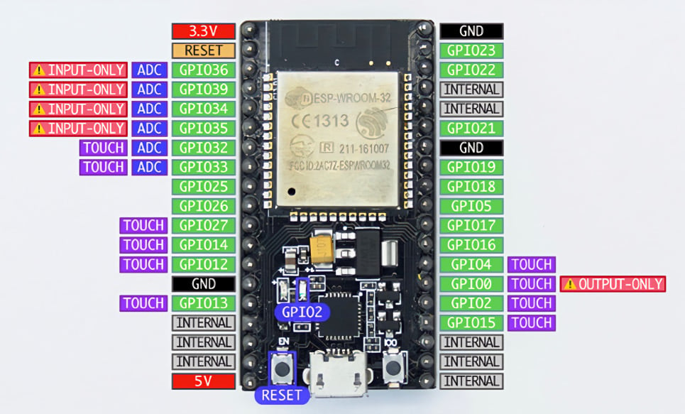
Figure 1.11 – NodeMCU ESP32S pinout diagram
We can now move forward and read from a sensor. The first sensor we will be working with is the BME680 sensor from Bosch Sensortech. This sensor can be easily found on Amazon, and it can measure relative humidity, barometric pressure, ambient temperature, and gas or volatile organic compounds (VOCs). You can find detailed information about this sensor at https://www.bosch-sensortec.com/products/environmental-sensors/gas-sensors/bme680/.
There are two ways to read the data produced by the sensor: through I2C or SPI. In this experiment, we will be communicating with the BME680 sensor through an I2C connection.
I2C, short for inter-integrated circuit, represents a connection method utilized in serial communication as a bus interface protocol. Commonly referred to as the Two-Wire Interface (TWI), it is a popular choice for short-range communication. This protocol relies on two bi-directional open-drain lines named SDA and SCL. The Serial Data (SDA) line facilitates data transmission, while the Serial Clock (SCL) line conveys the clock signal.
Since the I2C bus can be used to connect multiple devices, each device connected to the bus should have a different address to distinguish it from others.
We need to connect the SCL pin of the BME680 board to D22 on the ESP32 board (or IO22 on other ESP32 board), the SDA pin of BME680 to D21 on the ESP32, the VCC of BME680 to the 3V3 pin of the ESP32, and the GND pin on BME680 to the GND pin on ESP32. We can use the protoboard or direct jumper cable between those boards. The connection should look like that in the following figure:
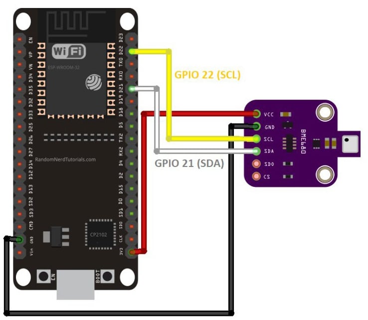
Figure 1.12 – Pinout diagram for attaching BME680 to ESP32
Working with the BME680
Due to the different addresses used by different BME680 board manufacturers, we need to verify the I2C address of the BME680 board we use (we also need to do this for every I2C device unless we already have the address from the manufacturer). To get the I2C address of the BME680 board, we need to use an I2C Scanner library:
- In Arduino IDE, we can easily find code for our requirements by using the Library Manager. To access it, click on Sketch | Include Library | Manage Libraries.
- Next, type
I2C scannerin the search bar. Several I2C scanner libraries will appear. The one we will be using is from Luis Llamas, but you can try other libraries as well. To install the library, click on the Install button. - Once the library is installed, go to Arduino, click on File, then Example. Scroll through the examples until you find I2C Scanner under Examples from Custom Libraries. Point to I2C Scanner and click on Scanner to open the example code. The Scanner sketch will appear in the Arduino window, and you can upload the code to your ESP32 board by clicking the
 button.
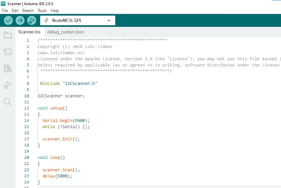
Figure 1.13 – Expected display for the IC2 Library in Arduino IDE
After finishing the upload, click on Tools | Serial Monitor to see the Arduino console (the older version will open a new window while the newer version will split the Serial Monitor under the Sketch window). You need to adjust the Serial Monitor baud rate to match the baud rate set in the program by finding the command in the void setup() function:
Serial.begin(9600);
This code sets the serial communication baud rate of the ESP32 board to 9600 baud, so we need to set the Arduino Serial Monitor window baud rate to 9600 to match the board. After this, we need to reset the ESP32 board by pressing the Reset button (marked EN) on the board.
If everything is set up properly, you will see the result in the Arduino window like in Figure 1.14:
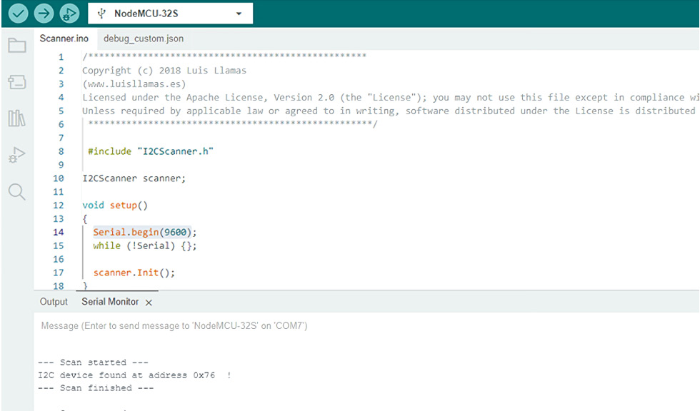
Figure 1.14 – Expected display for serial communication setup in Arduino IDE
Now we know that the BME680 board is using I2C address 0x76H.
- Click on Sketch | Include Library | Manage Libraries and search for
bme680. ChooseBSEC Software Libraryby Bosch Sensortec. Click on the Install button. After installing, click on File | Examples, scroll down through the examples until you findBSEC Software Library, and click on the basic sketch. It will open the sketch. You can find this sketch also in thei2csample.cfile in thePracticalfolder within theChapter01folder in the GitHub repository.Verify the sketch by clicking on the
 button, and if there’s no error, upload it to ESP32 by clicking the button.
 - Open the Serial Monitor, set the baud rate to
115200to match the sketch setting, and reset the board by pressing the EN button.
ESP32 Wi-Fi auto-configuration
The ESP32 has a built-in Wi-Fi functionality and can be set as an access point or a station. If it is set as an access point, you can connect your devices (mobile, other Wi-Fi devices, or computer) to it. If it is set as a station, you need to connect the ESP32 to an access point before you can read its data or it can send data to a remote server over the wireless network or internet (if the connected access point is connected to the internet). The ESP32 can also be set up as both an access point and station concurrently. This function is normally used to enable connecting the ESP32 to the available access point without having to manually configure the Wi-Fi setup and download it through a USB connection to the ESP32, which is difficult for common users.
There are two common methods of connecting the ESP32 to the Wi-Fi access point: manual and auto-configuration.
Manual configuration
The basic configuration of setting up an ESP32 connection to the access point involves manually entering the Wi-Fi SSID and password to the Arduino sketch and uploading it to the server using a serial USB cable. This manual Wi-Fi setup is very difficult to implement in real-life applications since many device users cannot do programming and Arduino IDE setup. Due to that issue, there is another way of setting up the Wi-Fi SSID and password—auto-connect configuration—which we will outline and use.
Auto-connect configuration
Another way to connect the ESP32 to the access point without having to hardcode the Wi-Fi SSID and password in the sketch and upload it to the ESP32 using a USB cable is by using auto-connect configuration. In this way, the ESP32 will be in the access point first, and if we connect to it using other devices (mobile phone or computer), it will display menus to guide us to connect to an available access point it can find by providing Wi-Fi credentials (i.e. SSID and password). Once we confirm, it will store the credentials in its memory, and then it will restart in Wi-Fi station mode and use the stored credentials to connect to the targeted access point. When we reset the ESP32, it will still be in station mode and will keep trying to connect to the designated access point.
One of the Arduino libraries that support auto-connect configuration is ESPAsync_WiFiManager, built by Khoi Hoang. The benefit of using asynchronous Transmission Control Protocol/User Datagram Protocol (TCP/UDP) connection is that the processor does not have to wait for each connection to finish before it can serve other requests, so multiple connections can occur concurrently. This will also enable faster responses.
ESPAsync_WiFiManager installation
Next, we will need to set up the ESPAsync_WifiManager library to configure the Wi-Fi connection for the ESP32 and proceed with our next steps:
- Search from
Manage Librariesto findESPAsync_WiFiManagerand install it. We also need to download the dependency libraryESPAsyncDNSServer, which, unfortunately, cannot be found via theManage Librariessearch. For libraries that cannot be found in the Library Manager search results, we can download them by searching for them on the internet and downloading the library as a.zipfile. We can download theESPAsyncDNSServerlibrary at https://github.com/devyte/ESPAsyncDNSServer and save the code as a.zipfile. - To install the
.zipfile library we just downloaded, click on Sketch | Include Library | Add Zip Library and select that file. - In a new Arduino sketch screen, click on File | Examples |
ESPAsync_WiFiManagerand open theAsync_AutoConnectsketch. Verify the sketch by clicking on the button, and if there are no errors, upload it to ESP32 by clicking the button. Reset the ESP32 board by pressing the Reset (marked EN) button.
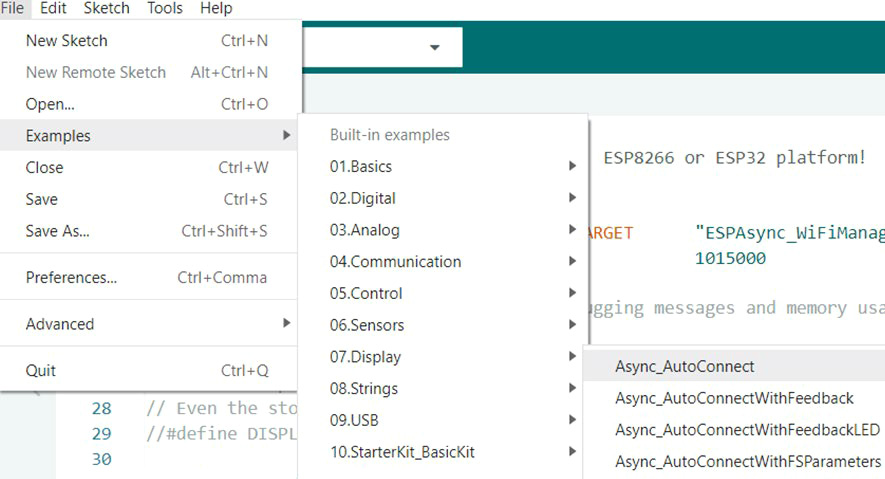
Figure 1.15 – Opening the Async_AutoConnect sketch on Arduino IDE
- From a mobile phone or computer, search for a Wi-Fi access point to find
ESP_******_AutoConnectAP, where******is the six digits of the hex number related to the ID of the ESP32. Connect to this access point with a password in the formatMyESP_******, where the******should be the same six-digit hex number as the ESP32 ID. After connecting to the ESP32 access point, a browser window will open. Follow the guidance from the menu to enter the targeted access point SSID that the ESP32 should connect to and enter the password for the Wi-Fi connection. Once set, and once the ESP32 connects to that access point, the ESP32 will reset, change the mode to station mode, and automatically connect to the access point.
With this, we have successfully prepared the ESP32 to be able to communicate over Wi-Fi. We can now move on to setting up programming over the air (OTA) to be able to create and publish our code directly to the ESP-32 instead of having to connect it to our laptop.
ESP32 programming OTA with a web server and mDNS
Programming OTA allows updates to the code or configurations to be pushed over Wi-Fi so that we do not have to continually connect the ESP32 to the Wi-Fi when we push out updates to it. We will explore how we can set up the ESP32 for this so that the process of pushing out updates can go much more smoothly.
Copy the sketch on the repo named programmingOTA.c in the Practical folder within the Chapter01 folder in the GitHub repository to the Arduino sketch window and save it as ESP32_ElegantOTA_mDNS.
Verify the code using the ![]() button and upload to ESP32 using the
button and upload to ESP32 using the ![]() button. Press the Reset (EN) You should get a welcome message in your browser.
button. Press the Reset (EN) You should get a welcome message in your browser.
ESP32 reading the BME680 sensor
Now, we can begin configuring the parameters that we want to have measured from the environment. To do this, we need to code up the necessary code for the sensors so that they can connect to the ESP32 and read in accordingly.
As part of this, we can configure the libraries and the code for the BME680 sensor, which allows us to measure gas, pressure, temperature, and humidity:
- You need to install additional libraries:
- The Adafruit
BME680library together with its dependencies, i.e.,Adafruit UnifiedSensor Library. - The
ESPAsyncWebServerlibrary from https://github.com/me-no-dev/ESPAsyncWebServer/archive/master.zip. Install this library by navigating to Sketch | Include Library | Add .ZIP Library and choose the downloaded file. - The
AsyncEleganOTAlibrary from https://github.com/ayushsharma82/AsyncElegantOTA. Install this library using the method in step B. - The
ESPmDNSlibrary from https://github.com/espressif/arduino-esp32. Install this library using the method in step B. - The
ESPAsynclibrary from https://github.com/me-no-dev/ESPAsyncTCP/archive/master.zip. Install this library using the method in step B.
- The Adafruit
- Copy the sketch in the
ESP32_BME680_OTA_mDNS.cfile in thePracticalfolder within theChapter01folder in the GitHub repository to a new Arduino sketch and save it asESP32_BME680_OTA_mDNS. Please do not forget to change the Wi-Fi SSID and password according to your Wi-Fi access point setup. - Verify the sketch by clicking on the button, and if there are no errors, upload it to ESP32 by clicking the button. Open the Serial Monitor and set the baud rate to 115200 to match the sketch setting and reset the board by pressing the EN button. Your Serial Monitor window should look like this:
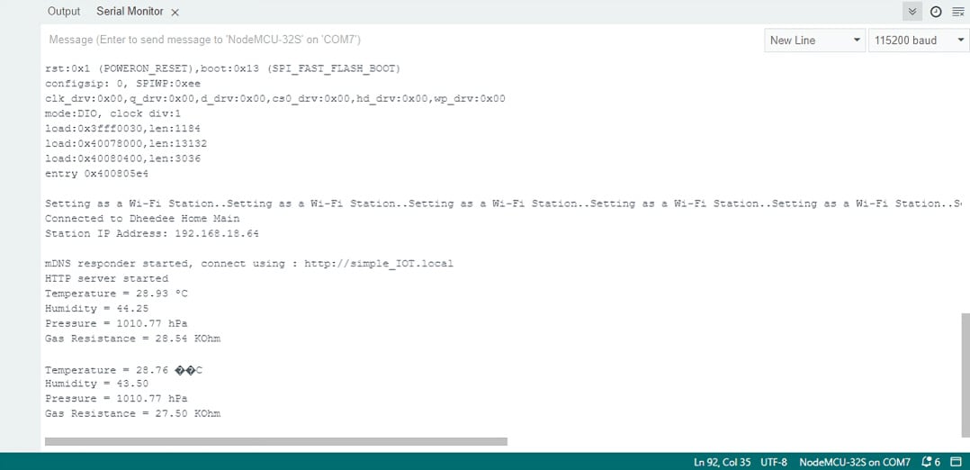
Figure 1.16 – Expected output from the Arduino IDE Serial Monitor
- As the code also creates a web server, you can see it being visualized by opening your web browser and typing the address
http://simple_IOT.local.
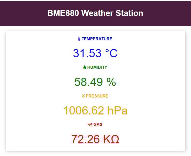
Figure 1.17 – Display on the local web server
And that’s it; you’ve made your first IoT-based project! Now upload the code to GitHub and see whether you can also make these modifications to your hardware/code to further understand and practice the concepts that you have learned through this practical exercise:
- Can you switch the BME680 sensor with a soil humidity sensor in your kit? Which modifications do you need to make to your circuit and software for that?
- Can you modify the sample rate of the data so that it samples two times in one second?
Feel free to use the documentation from the Keyestudio Super Starter Kit to help you navigate the use cases of each sensor and how to properly use them. Throughout this book, the internet is going to be an effective helper for you; particularly as there may be some concepts that you may not know. However, we always intend to explain each one as thoroughly as possible so that you do not need to do so.
Important note
When making changes to your code such as with these experimental problems, always make sure to commit your progress so that you can revert to previous versions when your current code does not work. This is important to remember, as you will certainly run into some dead ends in a project such as this and will need to backtrack to a working version to keep things on pace.
In this practical, you have learned how to create a mini weather station that can measure three different parameters. This will serve as a building block toward understanding the potential of IoT and for us to build on the concepts that have been learned here further in other practical exercises.
Summary
In this chapter, we learned what IoT is, how we utilize it in our everyday lives despite it not being the massive presence it is in large industries, and what the four pillars that constitute it are. We then set up our development environment, laying the foundation for the rest of the book. This involved configuring the ESP32 development and GitHub environments and introducing a simple IoT demo to familiarize you with the hardware and workflows we’ll be using throughout the book.
This chapter focused on selecting IoT hardware, covering considerations for different types and the trade-offs involved to ensure you choose the best option for your specific use case. We then discussed how to design a simple IoT system diagram, which will be the foundation for our more complex designs in the coming chapters, and how to connect smart objects to create the smart ecosystem that constitutes the IoT.
The hands-on experience was further enhanced by building a mini weather station in this chapter, allowing you to put the theory and skills you picked up thus far into practice and getting you more comfortable with working with IoT projects.
In the next chapter, we will be looking at the fundamentals of designing IoT networks and what to consider when doing so. This will build further on our skills for designing diagrams and making appropriate design factor decisions based on our use case.
Further reading
For more information about what was covered in this chapter, please refer to the following links:
- Learn more on getting started with GitHub: https://docs.github.com/en/get-started
- Understand more on what the Arduino IDE offers: https://docs.arduino.cc/learn/starting-guide/the-arduino-software-ide
- Learn more about the DHT module from Adafruit: https://learn.adafruit.com/dht
- Understand more about the concept of IoT: https://www2.deloitte.com/ch/en/pages/innovation/articles/iot-explained.html
- Get a better understanding of IoT microcontrollers: https://www.nabto.com/iot-microcontroller-guide/