Welcome to Instant Autodesk AutoCAD 2014 Customization with .NET. If you are new to writing custom AutoCAD applications, you are in for a real treat! There is great satisfaction that comes with knowing that you helped accelerate your company's or client's design process, improved drawing accuracy, minimized time spent on repetitive or demanding tasks, and reduced errors, all of which results in being able to deliver products faster than would have been possible without your custom CAD tools.
In this book, we'll create a toolbox full of small but useful AutoCAD plugins to handle common tasks: creating custom AutoCAD commands, reading and writing extended data, communicating with other applications, organizing and processing information, publishing drawings, and more. These are the building blocks of most custom AutoCAD programs. From these, you will conceive and develop more elaborate building blocks, specialized for your particular requirements. You will achieve productivity gains and improve the quality of your designs, products, and processes. Sound good? Let's get started!
This section will show you how to set up your development environment. Soon, you'll have everything you need to begin building your own high-powered applications for AutoCAD.
To work through the examples in this book, you must have (or obtain) the following software:
Autodesk AutoCAD 2014 (or a vertical product such as AutoCAD Mechanical 2014)
Microsoft Visual Studio 2010 (or Microsoft Visual C# 2010 Express Edition)
Microsoft .NET Framework 4.0
You should also download the following important items:
The AutoCAD 2014 ObjectARX SDK (http://www.objectarx.com)
The AutoCAD 2014 .NET Wizards (http://www.autodesk.com/developautocad)
If you don't already have AutoCAD 2014 installed, you can download a 30-day free trial version from Autodesk. We will use Microsoft Visual Studio 2010 as our development environment. You can use either the free version, called the Express Edition, or the paid version which goes by various names (Professional Edition, Premium Edition, and so on), depending on the tools and features included. Visual Studio will install .NET Framework 4.0 if it is not already installed.
First install Microsoft Visual Studio 2010 (or Visual C# 2010 Express Edition).
Next, go to www.objectarx.com and download and install ObjectARX 2014 SDK. While not strictly required (unless you are using the following AutoCAD .NET Wizards), there is an advantage to using the libraries in the SDK rather than those installed by default with AutoCAD (this will be covered in greater detail shortly).
Now, download the AutoCAD 2014 .NET Wizards for Visual Studio. The AutoCAD .NET Wizards are maintained by the DevTech team at Autodesk (Autodesk Developer Network, or ADN). The Wizards simplify your AutoCAD .NET project setup. You can download the AutoCAD 2014 .NET Wizards from www.autodesk.com/developautocad.
Before you install the AutoCAD 2014 .NET Wizards, right-click on the installer file,
AutoCADNetWizards.msi, and select Properties. In the Properties dialog box, select the Compatibility tab and enable the Run this program in compatibility mode for: Previous version of Windows option. Click on OK.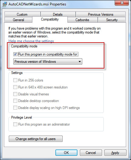
Install the AutoCAD 2014 .NET Wizards. By default these are installed at
C:\Program Files (x86)\Autodesk\AutoCAD 2014 .NET Wizards\.Tip
Downloading the example code
You can download the example code files for all Packt books you have purchased from your account at http://www.PacktPub.com. If you purchased this book elsewhere, you can visit http://www.PacktPub.com/support and register to have the files e-mailed directly to you.
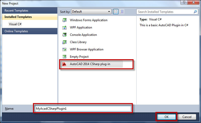
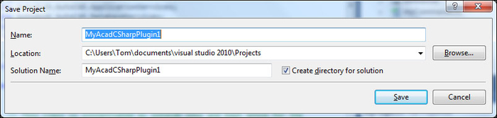
Now that the .NET Wizards are installed, open Microsoft Visual Studio and start a new project. Select the AutoCAD 2014 CSharp plug-in template and specify a name for the plugin. Click on OK.
In the AutoCAD .NET Wizard Configurator dialog, specify the location of
AcMgd.dllandacad.exe. The Express Editions of Visual Studio do not allow you to specify this executable file by name, although the Professional versions allow it. This information is required in order to debug our AutoCAD .NET plugins, so the Wizard essentially configures the Express Edition to enable debugging.While we could actually set these values manually by modifying our project's
.csproj.userfile (an XML file containing these settings as well as your platform configuration setting), we will allow the Wizard to handle this detail for us.
Before we dismiss the Configurator dialog box, we'll tell the Wizard which namespaces to include in our project. By default, the Wizard includes the AutoCAD and
AutoCAD.DatabaseServicesnamespaces. With our selections made, click on OK to close the Configurator and open our project.
We will make use of this project in the next task. For now, let's just save it.
When debugging an AutoCAD project, the paid version of Visual Studio 2010 offers better debugging capability than the Visual Studio 2010 Express Editions. We mitigate this by using the .NET Wizard. If you are using Visual C# 2010 Express Edition, which is used for the examples in this book, be sure to specify the Expert settings option (go to Tools | Settings | Expert settings). This ensures, among other things, that the Object Browser tool is accessible from the Visual C# 2010 Express Edition toolbar and menu.
The AutoCAD .NET Wizards require us to first install the ObjectARX 2014 SDK. The SDK ships with the same set of DLLs as those which are installed in the AutoCAD executable folder. As you saw, we linked to the DLLs that shipped with the ObjectARX 2014 SDK. This is the preferred method, as the DLLs in the SDK are simplified and contain no dependencies on the AutoCAD UI, unlike those which were installed with the product.
There is a separate, optional ObjectARX documentation installer available at the same location where you downloaded the ObjectARX 2014 SDK. This installer will integrate the ObjectARX 2014 help documentation with the Microsoft Visual Studio 2010 help system. This is not required in order to create .NET projects for AutoCAD, but I wanted to make you aware of the option. Much of the .NET API (Application Programming Interface) consists of .NET wrappers around the existing ObjectARX SDK functions. So, you might find it convenient to have the ObjectARX help files integrated with your development environment.
In Visual Studio, we specify the solution configuration. In the Build menu, click on Configuration Manager. Set Active solution configuration to Release (we'll use Debug in Controlling the drawing environment (Should know); <New...> and <Edit...> are beyond the scope of this book).
Our development environment is all set up. Now we'll put it to work and create a custom command for AutoCAD.
Some custom AutoCAD applications are designed to run unattended, such as when adrawing loads or in reaction to some other event that occurs in your AutoCAD drawing session (we'll look at these in a later chapter). However, the majority of your AutoCAD programming work will likely involve custom AutoCAD commands, whether automating a sequence of built-in AutoCAD commands, or implementing new functionality to address a business need. Commands can be simple (printing to the command window or a dialog box), or more difficult (generating a new design on-the-fly, based on data stored in an existing design). Our first custom command will be somewhat simple.
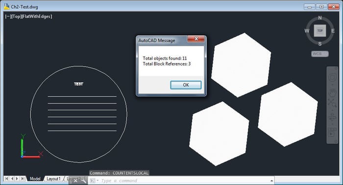
We will define a command which will count the number of AutoCAD entities found in ModelSpace (the space in AutoCAD where you model your designs). Then, we will display that data in the command window. Frequently, custom commands acquire information about an object in AutoCAD (or summarize a collection of user input), and then present that information to the user, either for the purpose of reporting data or so the user can make an informed choice or selection based upon the data being presented.
Note
Using Netload to load our command class
You may be wondering at this point, "How do we load and run our plugin?" I'm glad you asked! To load the plugin, enter the native AutoCAD command NETLOAD. When the dialog box appears, navigate to the DLL file, MyAcadCSharpPlugin1.dll, select it and click on OK. Our custom command will now be available in the AutoCAD session. At the command prompt, enter COUNTENTS to execute the command.
In our initial project, we have a class MyCommands, which was generated by the AutoCAD 2014 .NET Wizard. This class contains stubs for four types of AutoCAD command structures: basic command; command with pickfirst selection; a session command; and a lisp function. For this plugin, we will create a basic command, CountEnts, using the stub for the Modal command.
Working in the project which we began in the previous recipe, let's take a look at the code we will need in order to read the AutoCAD database, count the entities in ModelSpace, identify (and count) block references, and display our findings to users:
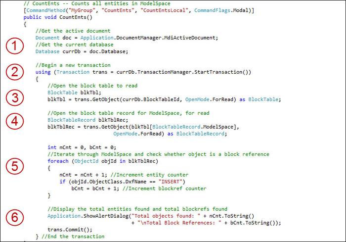
First, let's get the active AutoCAD document and the drawing database.
Next, begin a new transaction. Use the
usingkeyword, which will also take care of disposing of the transaction.Open the block table in AutoCAD. In this case, open it for read operation using the
ForReadkeyword.Similarly, open the block table record for
ModelSpace, also for read (ForRead) (we aren't writing new entities to the drawing database at this stage).We'll initialize two counters: one to count all AutoCAD entities; one to specifically count block references (also known as Inserts). Then, as we iterate through all of the entities in AutoCAD's
ModelSpace, we'll tally AutoCAD entities in general, as well as block references.Having counted the total number of entities overall, as well as the total number of block references, we'll display that information to the user in a dialog box.
AutoCAD is a multi-document application. We must identify the active document (the drawing that is activated) in order to read the correct database. Before reading the database we must start a transaction. In fact, we use transactions whenever we read from, or write to, the database. In the drawing database, we open AutoCAD's block table to read it. The block table contains the block table records ModelSpace, PaperSpace, and PaperSpace0. We are going to read the entities in ModelSpace so we will open that block table record for reading.
We create two variables to store the tallies as we iterate through ModelSpace, keeping track of both block references and AutoCAD entities in general. A block reference is just a reference to a block. A block is a group of entities that is selectable as if it was a single entity. Blocks can be saved as drawing files (.dwg) and then inserted into other drawings. Once we have examined every entity in ModelSpace, we display the tallies (which are stored in the two count variables we created) to the user in a dialog box. Because we used the using keyword when creating the transaction, it is automatically disposed of when our command function ends.
The Session command, one of the four types of command stubs added to our project by the AutoCAD 2014 .NET Wizard, has application (rather than document) context. This means it is executed in the context of the entire AutoCAD session, not just within the context of the current document. This allows for some operations that are not permitted in document context, such as creating a new drawing.
The other command stub, described as having pickfirst selection, is executed with pre-selected AutoCAD entities. In other words, users can select (or pick) AutoCAD entities just prior to executing the command and those entities will be known to the command upon execution.
Spending too much time setting up your drawing, configuring viewports, layouts, and so on? Our next project will simplify layout setup to just a few clicks.
In case you missed the previous section, we created a fairly simple command which displayed information about entities we (or someone) created in ModelSpace. Most of the plugins you'll create will draw, or otherwise process, AutoCAD entities on screen. By process, I mean the count, move, deform, delete, grow, shrink, change layer, change color, read entity properties (and report them), or read or write data that is attached to a specific entity or lives in an external file (for example, an Excel spreadsheet).
Other plugins are designed to assist in setting up the AutoCAD drawing environment, populating a title block, creating layers, layouts, and the like. In this project, we'll capture the configuration details from a selected layout in the active drawing. Then, we will clone the layout, its entities (such as viewports) and their properties, into a new drawing database, which we'll save as an AutoCAD template drawing. This template can be used to import specific layouts into our drawing, or to create entirely new drawings with the same layout configuration as the one that we cloned. But that's not all…
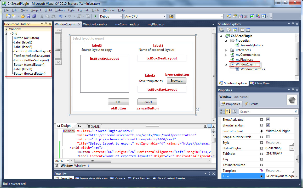
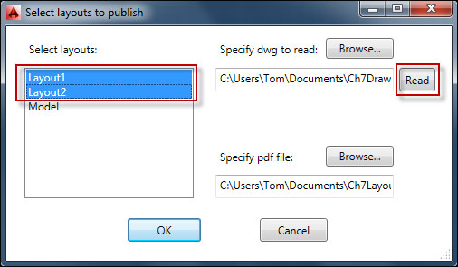
We will also create a simple, yet powerful, front end to drive this command: our user interface will specify the layout to export, the layout's new name in the template drawing, and the full filename of the template drawing that we are saving.
Following the examples from the previous recipes, create a new project, Ch3AcadPlugin. In the Configuration Manager, set the configuration type to Debug.
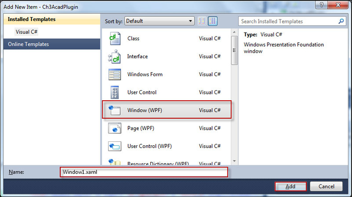
Add a Window to the project. Right-click on the project name Ch3AcadPlugin in the Solution Explorer, click on Add and then on Window… In the Add new item dialog box, select Window (WPF), specify the name Window1.xaml, and click on OK.
From the Toolbox (View | Toolbox), add some controls: a listbox, three textboxes, and three buttons to the window, as shown in the following screenshot. Name the controls according to the text in the screenshot (don't actually add the red text to your form). The buttons, textboxes, and listbox will also require event handler function definitions in the code: Click on the event handlers for the buttons, TextChanged event handlers for the textboxes, and a SelectionChanged event handler for the listbox.
Let's list the steps required to complete the task:
Open the
Window1.xaml.csfile in Visual Studio. At the top of the file, below the using System… statements, add three additional using statements:using Autodesk.AutoCAD.ApplicationServices; using Autodesk.AutoCAD.DatabaseServices; using AcadApp = Autodesk.AutoCAD.ApplicationServices;
In the
Window1class definition, add three string variables:namespace Ch3AcadPlugin { /// <summary> /// Interaction logic for Window1.xaml /// </summary> public partial class Window1 : Window { public static string txtSrcLayout; public static string txtDestLayout; public static string txtSavLayoutIn the
Window()method, just below InitializeComponent(), add code to get the active document and database:public Window1() { InitializeComponent(); //Get active drawing and database Document doc = AcadApp.Application.DocumentManager.MdiActiveDocument; Database db = doc.Database;Next, we'll begin a transaction. Open the
Layoutdictionary and read the layout associated with eachObjectId. After populating our listbox with all of the layout names, we commit (and end) the transaction://Read layout names from layout dictionary and populate listbox using (Transaction tr = db.TransactionManager.StartTransaction()){ //Get each entry in the layout dictionary DBDictionary loDic = tr.GetObject(db.LayoutDictionaryId, OpenMode.ForRead, false) as DBDictionary; foreach (DBDictionaryEntry entry in loDic) { ObjectId loId = entry.Value; //Open the layout for read Layout lo = tr.GetObject(loId, OpenMode.ForRead) as Layout; //Add the layout name to the listbox this.listBoxSrcLayout.Items.Add(lo.LayoutName); } tr.Commit(); }//end transactionNow, we'll work with the
Clickevent handlers for the OK and Cancel buttons. First, let's start with the Cancel button://'Click' event handler for 'Cancel' button private void cancelButton_Click(object sender, RoutedEventArgs e){ this.Close(); //close the dialog }Add a
Clickevent handler for the OK button. Set the three variables we declared at the top of the file to the values contained in the textboxes and listbox. Then, call thelayoutToTmplt()function (in theMyCommandsclass), which will export the layout:private void okButton_Click(object sender, RoutedEventArgs e) { //Get values from textboxes and listbox txtDestLayout = txtBoxDestLayout.Text; txtSrcLayout = listBoxSrcLayout.SelectedItem.ToString(); txtSavLayout = txtBoxSavLayout.Text; this.DialogResult = true; this.Close(); //close the dialog //Call layoutToTmplt() to export the selected layout MyCommands.layoutToTmplt(); }The final modification to the UI code is the event handler for the Browse button:
private void browseButton_Click(object sender, RoutedEventArgs e){
   //Create SaveFileDialog
   Microsoft.Win32.SaveFileDialog dlg = new
     Microsoft.Win32.SaveFileDialog();
   //Set filter for file extension and default file extension
   dlg.DefaultExt = ".dwg";
   dlg.Filter = "Drawing (*.dwg)|*.dwg";
   //Display SaveFileDialog
   Nullable<bool> result = dlg.ShowDialog();
   //If file is selected, display file name in textbox
   if (result == true) {
       //Get the document filename from the dialog
       string fn = dlg.FileName;
       //Populate textbox with the document filename
      txtBoxSavLayout.Text = fn;
   }
}
That (and the empty event handlers for the other controls) completes the user interface code in
Window1.xaml.cs. The MyCommands class is where we will add the other methods, layoutToTemplt() and ShowDialog(). Let's create a new command XPLayout. Originally, I'd chosen ExportLayout, but there are other Export commands, and you have to type all the way toExportLto get the correct command (and that's too long). XPLayout calls just one tiny method,ShowDialog():CommandMethod("XPLayout")] public void XPLayout() { ShowDialog(); } public void ShowDialog() { Window1 mw = new Window1(); Application.ShowModalWindow(mw); }Add a method named
layoutToTmplt()and get the database of the current drawing. Also, create a temporary database for the template layout:public static void layoutToTmplt() { //Get current (reference) drawing database Database db1 = Application.DocumentManager.MdiActiveDocument.Database; Editor ed = Application.DocumentManager.MdiActiveDocument.Editor; //Temp database for template layout Database db2 = new Database(true, false);In a transaction, set the working database to the temp database. Add a layout to the temp database:
using (Transaction trans1 =
   db2.TransactionManager.StartTransaction()) {
   //Switch working database to temp database
   HostApplicationServices.WorkingDatabase = db2;
   //Add a layout to the temp database
   LayoutManager loMgr1 = LayoutManager.Current;
   ObjectId oIdLo2 = loMgr1.CreateLayout(Window1.txtDestLayout);
   Layout lo2 = (Layout)trans1.GetObject(oIdLo2,
      OpenMode.ForWrite);
We'll set the working database back to our reference database. Begin a new transaction, nested within our first transaction. Now, open the reference layout for read and copy it into the temp layout:
//Switch the working database back to reference database
HostApplicationServices.WorkingDatabase = db1;
using (Transaction trans2 =
   db1.TransactionManager.StartTransaction()) {
   //Get the Layout in the reference database
    LayoutManager loMgr2;
    loMgr2 = LayoutManager.Current;
   ObjectId oIdLo1 = loMgr2.GetLayoutId(Window1.txtSrcLayout);
   Layout lo1 = (Layout)trans2.GetObject(oIdLo1,OpenMode.ForRead);
   //Copy reference layout into temp layout
    lo2.CopyFrom(lo1);
Open the reference layout's block table record (for read). Add all of the
ObjectIdsin the block table record to a collection, and clone the reference layout's objects to the temp layout://Get block table record of reference layout BlockTableRecord btr = default(BlockTableRecord); btr = BlockTableRecord)trans2.GetObject(lo1.BlockTableRecordId, OpenMode.ForRead); //Make collection of object ids from reference layout block //table record ObjectIdCollection oIdCln = new ObjectIdCollection(); foreach (ObjectId oId in btr) oIdCln.Add(oId); //Clone objects in the reference layout to the temp layout IdMapping iMap = new IdMapping(); db2.WblockCloneObjects(oIdCln, lo2.BlockTableRecordId, iMap, DuplicateRecordCloning.MangleName, false);Finally, commit the inner (second) transaction, and then the outer (first) transaction. Save the temp layout as a
.dwgfile:trans2.Commit(); } trans1.Commit(); //Save the temp database as a .dwg template db2.SaveAs(Window1.txtSavLayout, DwgVersion.Newest); }
This project uses AutoCAD's WBlockClone operation to clone AutoCAD objects across databases. For our purposes, this means cloning from a reference database (the current drawing) to a temporary database (the template database).
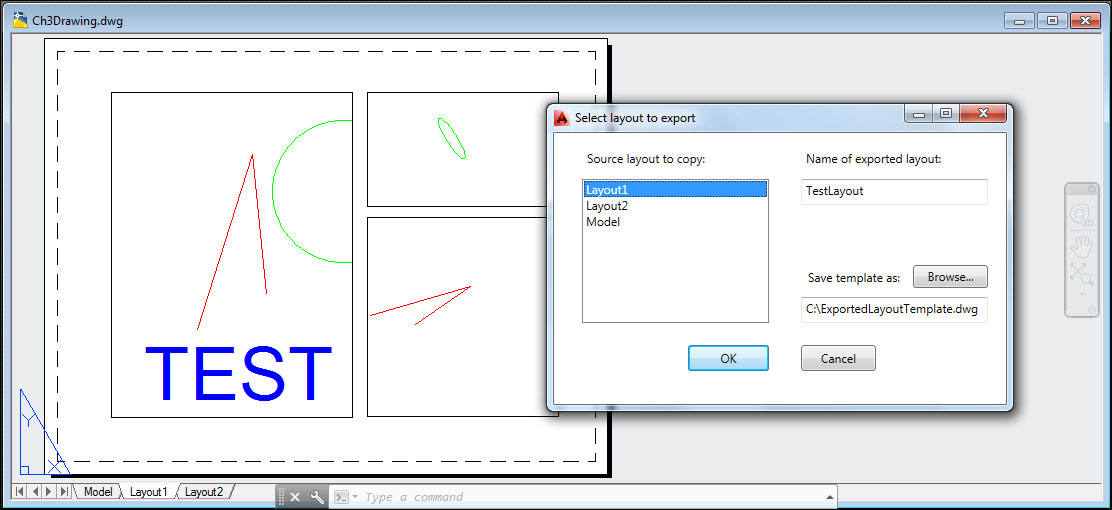
To run the code in Debug mode in Visual Studio, click on Start Debugging in the Debug menu, or click on the green arrowhead symbol on the standard toolbar. When AutoCAD starts, type NETLOAD, navigate to and select Ch3AcadPlugin.dll. Then, in AutoCAD, open Ch3Drawing.dwg (included in the code bundle) and execute the XPLAYOUT command.
The ShowDialog() method displays the custom dialog box we created. The dialog accepts three inputs: the name of the source, or reference layout; the name of the layout when it is exported to an external drawing file; and the name of the template drawing file. When you click on OK, the WBlockClone operation is carried out across databases.
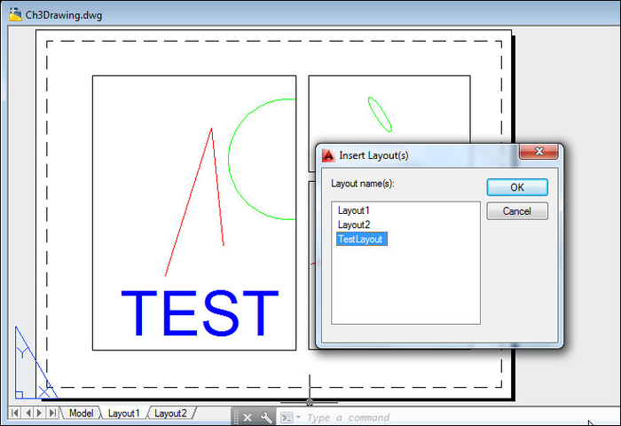
After the XPLAYOUT command is executed, try importing the exported layout. In AutoCAD, right-click on any layout tab and click on From template.... In the dialog box, specify the template drawing file that contains the exported layout.
In the Insert Layout(s) dialog box, select the layout we previously exported.
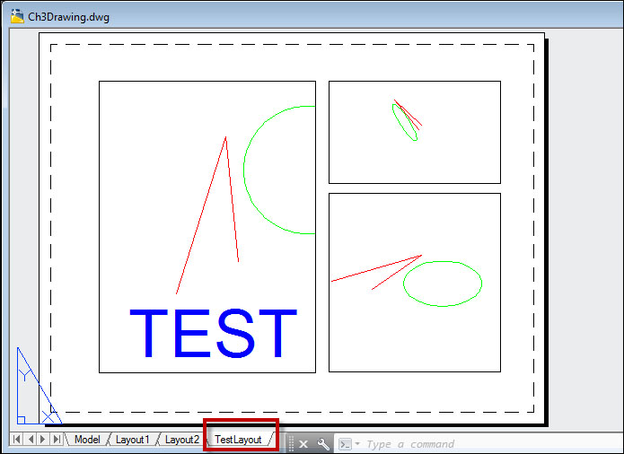
A new layout tab appears in the drawing window. Note that the cloned layout contains the same objects (viewports, text) as the reference layout.
Blocks are collections of AutoCAD entities, which can be moved, erased, copied, scaled, or mirrored with a single cursor pick. Blocks are well-suited to represent standard parts such as fasteners, fixtures, gears, and motors. We can attach attributes (data) to blocks, which represent properties that our custom program can read and respond to. This project demonstrates block insertion, reading and writing attribute values, and setting block reference properties.
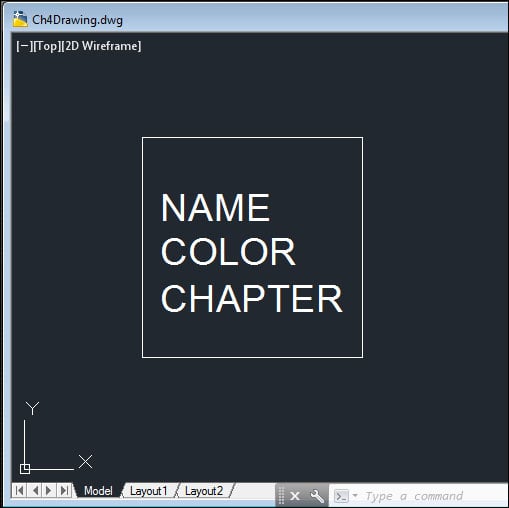
The code project is intended to be used with a test drawing, Ch4Drawing.dwg. The test drawing contains a block definition Test Block, which contains three attributes: Name (the block name), Color (a color/layer name), and Chapter (the current chapter). The first two can be set by end users, inserting the block in the drawing, and can also be read and modified by our code project. The third is a constant attribute, meaning that its value stays the same and is not set by the end user or by code.
Let's create a new command,
InsBlkAtt. Inside the transaction, we'll create an array of six layer names. As in the previous project, open the block table for read. This time, check for a block definition named Test Block (Test Block is defined inCh4Drawing.dwg, which is included with your downloaded code package):[CommandMethod("MyGroup", "InsBlkAtt", "InsBlkAtt", CommandFlags.Modal)] public void InsBlkWithAtts() { Database db = Application.DocumentManager.MdiActiveDocument.Database; Editor ed = Application.DocumentManager.MdiActiveDocument.Editor; PromptPointResult ptRes; int iCtr = 0; do { using (Transaction trans = db.TransactionManager.StartTransaction()){ string[] lyrNam = { "RED", "YELLOW", "GREEN", "CYAN", "BLUE", "MAGENTA" }; string blkNam = "Test Block"; //Open the block table for read BlockTable blkTbl = db.BlockTableId.GetObject(OpenMode.ForRead) as BlockTable; //Check the block table for block definition "Test Block" if (blkTbl.Has(blkNam) == false) { return; //exit if not found }If found, open the Test Block definition for read:
//Open "Test Block" definition for read
BlockTableRecord blkDefn = blkTbl[blkNam].GetObject(OpenMode.ForRead) as BlockTableRecord;
Also, open
ModelSpacefor write (we will be inserting block references inModelSpace)://Open ModelSpace for write BlockTableRecord mdlSpc = blkTbl[BlockTableRecord.ModelSpace].GetObject(OpenMode.ForWrite) as BlockTableRecord;
Next, add some code to prompt the user to pick an insertion point for the block reference on screen (configure the options to exit the command if the user right-clicks on or presses Enter). Then insert the block reference at the specified point:
//Set prompt string and options for "Test Block" insertion point
PromptPointOptions ptOpts = new PromptPointOptions
   (System.Environment.NewLine + "Select insertion point");
ptOpts.AllowNone = true; //Allow Enter key/Right-click as input
ptRes = ed.GetPoint(ptOpts); //Get insertion point
//If point was picked or coords entered, continue; otherwise, exit
if (ptRes.Status != PromptStatus.OK) {
   ed.WriteMessage("Done.");
   return;
}
double X = ptRes.Value.X;
double Y = ptRes.Value.Y;
using (BlockReference blkRef =
   new BlockReference(new Point3d(X, Y, 0), 	blkDefn.ObjectId)) {
   string blkClr = "";
   //Append block ref to ModelSpace
   mdlSpc.AppendEntity(blkRef);
   trans.AddNewlyCreatedDBObject(blkRef, true);
Check the block definition for attribute definitions and create attribute references for them (unless they are constant attributes):
foreach (ObjectId oId in blkDefn) {
   DBObject dbObj = oId.GetObject(OpenMode.ForRead);
   AttributeDefinition aDefn = dbObj as AttributeDefinition;
   if (aDefn != null) {
      //If not a 'constant' attribute, create a reference
      if (aDefn.Constant == false) {
         using (AttributeReference aRef =
            new AttributeReference()) {
         aRef.SetAttributeFromBlock(aDefn, blkRef.BlockTransform);
If there is a
COLORattribute, open the layer table for read:if (aDefn.Tag == "COLOR") { LayerTable lTbl = (LayerTable)trans.GetObject (db.LayerTableId, OpenMode.ForRead);If a layer has the same name as the layer name indexed in the array, set the
COLORattribute value (TextStringproperty) to that layer name. Also, set the block reference's Layer property to match theCOLORattribute (at the same time, advance the index to point to the next layer name in the array):if (lTbl.Has(lyrNam[iCtr])) { //Set attribute value to layer name indexed //in array, if it exists aRef.TextString = lyrNam[iCtr]; if (iCtr == 5) { iCtr = 0; //Only six layers added so reset to 0 } else { iCtr = iCtr + 1; //Increment counter by 1 } //Set block ref layer to same as attribute value blkClr = aRef.TextString; blkRef.Layer = blkClr; }If there is a
NAMEattribute, set its value to the block name, Test Block:else if (aDefn.Tag == "NAME") { //Set attribute value to block name aRef.TextString = blkNam; }Finally, append the attribute references to the block reference. Continue to prompt the user for an insertion point until they exit the command by right-clicking, or by pressing the ENTER or Esc keys:
//Append attribute reference to block ref
  blkRef.AttributeCollection.AppendAttribute(aRef);
               trans.AddNewlyCreatedDBObject(aRef, true);}}
            }
         }
      }
      trans.Commit();
   } //End transaction
} while (ptRes.Status == PromptStatus.OK);
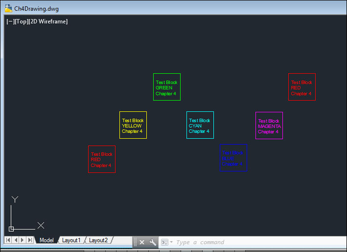
The drawing has six layers named for their colors: red, yellow, green, cyan, blue, and magenta. The program prompts the user to pick an insertion point on screen. With each insertion, the program cycles through an array of layer names and the COLOR attribute of each inserted block is set to a different color/layer name, until the end of the array is reached and the cycle begins again. The program reads the COLOR attribute on each block reference, and sets the block's layer property according to the attribute value. Since the block was defined with the color set to Bylayer, the entities in the block reference take on the color of the layer to which they are assigned.
CAD data is not limited to layers, linetypes, and point coordinates. Let's make an application that reads and manipulates data that you store in AutoCAD objects. While our example is simple, in the real world this data could represent material type, weight, cost, inventory, supplier data, and more. We saw how we can attach attributes (text data) to block references in AutoCAD drawings. However, we work with other AutoCAD object types in addition to blocks, and we may also wish to represent data using other data types (integers, reals, 2D and 3D points, and more). We can accomplish this by using extended entity data, or xdata for short.
In this project, which can be used with virtually any AutoCAD drawing, we will create commands which add (attach) xdata to an AutoCAD object, read and display xdata found on an object, and also remove specific xdata from an object.
Create a new command,
AddXD. Get the current drawing'sDatabaseandEditorobjects:[CommandMethod("AddXD")] static public void AddXD() { //Get the curr dwg database Database db = Application.DocumentManager.MdiActiveDocument.Database; //Begin a transaction using (Transaction trans = db.TransactionManager.StartTransaction()) { //Get the Editor object of current drawing Editor ed = Application.DocumentManager.MdiActiveDocument.Editor;Add code to prompt the user to select an object on screen (configure the options to exit the command if the user right-clicks on or presses ENTER):
//Select an object on screen
PromptEntityOptions prEntOpts = new PromptEntityOptions(
   "Select object");
prEntOpts.AllowNone = true; //Allow Enter key/Right-click as input
PromptEntityResult prEntRes = ed.GetEntity(prEntOpts);
if (prEntRes.Status != PromptStatus.OK) {
   ed.WriteMessage("Done.");
   return;
}
Open the selected object for read. Retrieve the handle of the object, as well as the object's layer name. Now, upgrade the
OpenModetoForWrite, since we will be writing xdata to the object://Open the selected object for read Entity acEnt = (Entity)trans.GetObject(prEntRes.ObjectId, OpenMode.ForRead); //Get the handle for the selected object Handle acHndl = acEnt.Handle; //Get the layer name for the selected object string lyrName = acEnt.Layer.ToString(); acEnt.UpgradeOpen();
Open the
regapptable and check for your appid (a unique identifier for accessing this set of data). I suggest changing it fromTESTto something more original. If your appid is not found, upgrade theregapptable'sOpenModetoForWrite, create a newregapptable record and then add your appid:RegAppTable regTbl = (RegAppTable)trans.GetObject(db.RegAppTableId, OpenMode.ForRead); if (!regTbl.Has("TEST")) { regTbl.UpgradeOpen(); RegAppTableRecord regTblRec = new RegAppTableRecord(); regTblRec.Name = "TEST"; regTbl.Add(regTblRec); trans.AddNewlyCreatedDBObject(regTblRec, true); }Finally, attach a variety of xdata types to the selected AutoCAD object. Add the xdata to a
ResultBufferand set the object's xdata property to the contents of the buffer. Once the xdata is attached, dispose of theResultBuffer:ResultBuffer resBuf = new ResultBuffer(new TypedValue(1001, "TEST"), new TypedValue(1000, "An integer:"), new TypedValue(1070, 0521), new TypedValue(1000, "Handle of selected object:"), //Handle of the object you picked new TypedValue(1005, acHndl), new TypedValue(1000, "Open bracket:"), //'Opening' control bracket for nested xdata new TypedValue(1002, "{"), new TypedValue(1000, "Layer of selected object:"), new TypedValue(1003, acEnt.Layer.ToString()), new TypedValue(1000, "Close bracket"), //'Closing' control bracket for nested xdata new TypedValue(1002, "}")); acEnt.XData = resBuf; resBuf.Dispose(); trans.Commit(); } //end transactionCreate another command,
ReadXD. As before, get theDatabaseandEditorobjects, and prompt the user to select an object. Also, check theregapptable for your appid:[CommandMethod("ReadXD")] static public void ReadXD() { //Get the curr dwg database Database db = Application.DocumentManager.MdiActiveDocument.Database; //Begin a transaction using (Transaction trans = db.TransactionManager.StartTransaction()) { //Get the Editor object of current drawing Editor ed = Application.DocumentManager.MdiActiveDocument.Editor; //Select an object on screen PromptEntityOptions prEntOpts = new PromptEntityOptions("Select object"); prEntOpts.AllowNone = true; //Allow Enter key/Right-click PromptEntityResult prEntRes = ed.GetEntity(prEntOpts); if (prEntRes.Status != PromptStatus.OK) { ed.WriteMessage("Done."); return; } //Open the selected object for read Entity acEnt = (Entity)trans.GetObject(prEntRes.ObjectId, OpenMode.ForRead); //Open the regapp table and check for your appid RegAppTable regTable = (RegAppTable)trans.GetObject(db.RegAppTableId, OpenMode.ForRead);If your appid exists in the table, retrieve the xdata from the selected object. Use a
ResultBufferto capture the xdata. Loop through the buffer, testing each item for its xdata type code. Display the xdata (adding some descriptive information) in AutoCAD's textscreen (press the F2 key to toggle the textscreen visibility):if (regTable.Has("TEST")) { //Replace "TEST" with your own appid //If the appid exists in the regapp table, attempt to read the //object's xdata from the table ResultBuffer resBuf = acEnt.GetXDataForApplication("TEST"); if (resBuf != null) { TypedValue[] resBufArray = resBuf.AsArray(); foreach (TypedValue val in resBufArray) { switch ((DxfCode)val.TypeCode) { //Appid type xdata case DxfCode.ExtendedDataRegAppName: string appid = (string)val.Value; ed.WriteMessage(System.Environment.NewLine + "1001 AppId: {0}", appid); break; //String type xdata case DxfCode.ExtendedDataAsciiString: string strng = (string)val.Value; ed.WriteMessage(System.Environment.NewLine + "1000 String: {0}", strng); break; //LayerName type xdata case DxfCode.ExtendedDataLayerName: string laynam = (string)val.Value; ed.WriteMessage(System.Environment.NewLine + "1003 Layer: {0}", laynam); break; //Handle type xdata case DxfCode.ExtendedDataHandle: ed.WriteMessage(System.Environment.NewLine + "1005 Handle: {0}", val.Value); break; //Control type xdata case DxfCode.ExtendedDataControlString: string brkt = (string)val.Value; ed.WriteMessage(System.Environment.NewLine + "1002 Control: {0}", brkt); break; //Integer type xdata case DxfCode.ExtendedDataInteger16: Int16 intgr = (short)val.Value; ed.WriteMessage(System.Environment.NewLine + "1070 Integer: {0}", intgr); break; default: ed.WriteMessage(System.Environment.NewLine + "Unknown type: {0}", val.Value); break; }//switch }//foreach } else { ed.WriteMessage(System.Environment.NewLine + "No xdata found for appid: TEST"); } trans.Commit(); } else { ed.WriteMessage(System.Environment.NewLine + "No xdata found for appid: TEST"); }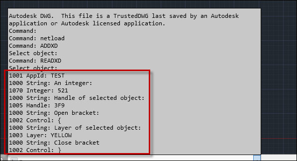
Create a command named
RemXDto remove xdata associated with a particular appid. Add code, as in the other two commands, to prompt the user to select an object:[CommandMethod("RemXD")] static public void RemXD() { //Get the curr dwg database Database db = Application.DocumentManager.MdiActiveDocument.Database; //Begin a transaction using (Transaction trans = db.TransactionManager.StartTransaction()) { Editor ed = Application.DocumentManager.MdiActiveDocument.Editor; //Select an object on screen PromptEntityOptions prEntOpts = new PromptEntityOptions("Select object"); prEntOpts.AllowNone = true; //Allow Enter key/Right-click PromptEntityResult prEntRes = ed.GetEntity(prEntOpts); if (prEntRes.Status != PromptStatus.OK) { ed.WriteMessage("Done."); return; } //Open the selected object for read Entity acEnt = (Entity)trans.GetObject(prEntRes.ObjectId, OpenMode.ForRead); ResultBuffer resBuf = acEnt.GetXDataForApplication("TEST");If there is xdata associated with your appid, remove it by setting the object's
XDataproperty to an emptyResultBuffer(empty, except for your appid):if (resBuf != null) { acEnt.UpgradeOpen(); acEnt.XData = new ResultBuffer(new TypedValue(1001,"TEST")); resBuf.Dispose(); } trans.Commit(); }
AutoCAD maintains a regapp table which contains a regapp table record for every appid. Xdata persists with an object (entity) between drawing sessions. You can have more than one appid associated with an object, but you can only retrieve the xdata associated with a particular appid. There is also an xdata command for end users to specify an appid and add XData to an object. The main disadvantage of xdata is its size limitation. It is recommended to have no more than 1 KB of xdata attached to any one AutoCAD object.
If you require more data per object, AutoCAD has an alternative to xdata called the xrecord, which lives either in the drawing's NamedObject Dictionary (NOD) or in a specific object's extension dictionary. Unlike xdata, xrecords are not subject to the 1 KB size limitation and hold much more data than xdata. Working with xrecords is outside the scope of this book.
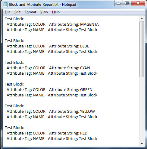
Information is key to the productivity of any CAD shop. The ability to capture, organize, and present your AutoCAD object data means that you can provide real intelligence with your drawing package. This project scans all block references in a drawing and writes the block name and attribute names and values to a text file. This idea could be expanded and improved by adding better formatting, different output types, reading xdata in addition to attributes, and so on (feel free to borrow code from the previous exercises).
This program creates a blank text file, C:\ Block_and_Attribute_Report.txt, if it doesn't already exist. There is no drawing provided for this chapter. Either create a drawing with a variety of block references and attributes, or use an existing drawing.
You will also need to add some additional system references to your myCommands.cs file:
using System;
using System.IO;
using System.Text;
using System.Windows.Forms;
using Microsoft.VisualBasic.Devices;

using Autodesk.AutoCAD.Runtime;
using Autodesk.AutoCAD.ApplicationServices;
using Autodesk.AutoCAD.DatabaseServices;

using Autodesk.AutoCAD.Geometry;
using Autodesk.AutoCAD.EditorInput;
using AcadApp = Autodesk.AutoCAD.ApplicationServices.Application;
Add a static property to the project for the text file object, and a string constant to hold the filename:
namespace Ch6AcadPlugin {
   public class MyCommands {
      private static FileInfo oDatFile { get; set; }
      const string sFilename =
         "C:\\Block_and_Attribute_Report.txt";
Add a new command, WData. Get the current drawing
DatabaseandEditorobjects. Add a function call toCreateDatFile(). We'll add the function itself shortly. Use try...catch blocks to catch any exceptions:[CommandMethod("WData")] public void WriteData() { Document doc = AcadApp.DocumentManager.MdiActiveDocument; Editor ed = doc.Editor; //Get the current database Database currDb = doc.Database; //Create the data file, to be updated later. try { CreateDatFile(); } catch (System.Exception ex) { ed.WriteMessage((System.Environment.NewLine + "Problem creating data file. " + ex.Message)); return; }Inside the transaction, add a filter to build a selection set of all the block references in the drawing. Create an array of all the block reference ObjectIDs:
using (Transaction tr =
   currDb.TransactionManager.StartTransaction()) {
   try {
      // Filter only the block references
      TypedValue[] filList = new TypedValue[1] {
         new TypedValue((int)DxfCode.Start, "INSERT") };
      SelectionFilter filter = new SelectionFilter(filList);
      PromptSelectionResult res = ed.SelectAll(filter);
      SelectionSet selSet = res.Value;
      ObjectId[] idArray = selSet.GetObjectIds();
      string sBlk = "";
      string sAtt = "";
Now, if the text file exists, iterate thorough the block reference IDs. Get the block name as well as the attribute tags and their values (build a string with all of the attribute tags and values):
      if (oDatFile.Exists) {
        FileStream fs = File.Create(sFilename);
        foreach (ObjectId blkId in idArray) {
          BlockReference blkRef =
          (BlockReference)tr.GetObject(blkId,OpenMode.ForRead);
          BlockTableRecord btr =
          (BlockTableRecord)tr.GetObject (blkRef.BlockTableRecord,
             OpenMode.ForRead);
          sBlk = btr.Name.ToString();
          sAtt = "";
          btr.Dispose();
          AttributeCollection attCol = blkRef.AttributeCollection;
          foreach (ObjectId attId in attCol) {
             AttributeReference attRef =
               (AttributeReference)tr.GetObject (attId,
                  OpenMode.ForRead);
             string str = ("  Attribute Tag: " + attRef.Tag
            	   + "   Attribute String: " + attRef.TextString);
             sAtt = sAtt + str + System.Environment.NewLine;
          }
Write the block and attribute data to the text file, and close it (it will be automatically saved). And that's it! In step 6, we'll write the function to create the text file:
            //Write data text to the data file.
            byte[] info = new UTF8Encoding(true).GetBytes(sBlk
               + ":::" + sAtt + System.Environment.NewLine);
            fs.Write(info, 0, info.Length);
         }
         fs.Close(); //Close the file
      }
      else {
         MessageBox.Show("Unable to update data file.",
           "Ch6AcadPlugin", MessageBoxButtons.OK,
           MessageBoxIcon.Error);
         throw new ApplicationException();
      }
      tr.Commit();
   }
   catch (Autodesk.AutoCAD.Runtime.Exception ex) {
      ed.WriteMessage(("Exception: " + ex.Message));
   }
   finally {
      tr.Dispose();
   }
}
Add a function,
CreateDatFile(). The function will create the blank data file or overwrite the previous one://Create the data file, to be updated later. private static void CreateDatFile() { // Create or overwrite the data file. try { oDatFile = null; Computer myComputer = new Computer(); oDatFile = myComputer.FileSystem.GetFileInfo(sFilename); if (oDatFile.Exists == false) { FileStream fs = File.Create(sFilename); oDatFile = myComputer.FileSystem.GetFileInfo(sFilename); fs.Close(); } } catch (System.Exception ex) { MessageBox.Show("Unable to create data file." + System.Environment.NewLine + ex.Message, "Ch6AcadPlugin", MessageBoxButtons.OK, MessageBoxIcon.Error); throw new ApplicationException(); } }
After using some System IO calls to create the new file, we use a filter to build a selection set made up of only the block references in the drawing. From the selection set, we derive an array of the block reference ObjectIds. We open each block reference for read, get the block name, and check for attributes. If attributes exist, we build a string containing all of the attribute tags and values. Once we've iterated through all of the attributes, we write the data we've captured to the text file we've designated for this purpose.
The next project lets your users select layouts from an external drawing not currently opened in AutoCAD, and then publish those layouts as a multisheet PDF file.
How do we publish layouts that exist in drawings that are not open in the current drawing session? You might recall back in the Controlling the drawing environment (Should know) recipe, when we cloned a layout from the current drawing into a side database, and from there we saved the layout to a template drawing. Now, we have a slight variation on that theme: when the user selects the external drawing, the program reads it into a temporary database, determines the number of layouts, and adds the layout names to the dialog box (also slightly modified from its predecessor in the Controlling the drawing environment (Should know) recipe). The user selects the desired layouts and the custom program tells AutoCAD to publish them using AutoCAD's Publisher API. Similar to the example in Controlling the drawing environment (Should know), we will create a small dialog box interface using Microsoft's Windows Presentation Foundation (WPF) (more about this in a moment).
First, we'll add statements for AutoCAD's plotting service and Windows forms:
using System;
using System.IO;
using System.Text;
using System.Windows.Forms;
using Autodesk.AutoCAD.Runtime;
using Autodesk.AutoCAD.ApplicationServices;
using Autodesk.AutoCAD.DatabaseServices;
using Autodesk.AutoCAD.Geometry;
using Autodesk.AutoCAD.EditorInput;
using Autodesk.AutoCAD.PlottingServices;
using AcadApplication = Autodesk.AutoCAD.ApplicationServices.Application;

// This line is not mandatory, but improves loading performances
[assembly: CommandClass(typeof(Ch7AcadPlugin.MyCommands))]
namespace Ch7AcadPlugin {

    public class MyCommands {

        //Command to publish selected layouts
        //in an external dwg to a pdf file
        [CommandMethod("LOPUB")]
        public void PubSelLo() {
            ShowDialog();
        }

        //Display dialog box to specify external drawing,
        //pdf file, and layouts to publish
        public void ShowDialog() {
            Window1 mw = new Window1();
            AcadApplication.ShowModalWindow(mw);
        }
Once the user clicks on OK, we are almost ready to publish. First, we must set the AutoCAD system variable
BackgroundPlotto0, so AutoCAD will plot in the foreground. Then, we will get the filename and path of the external drawing://Publish layouts selected from an external drawing to a pdf file public static void PubLo2Pdf() { //Get the active document Document oDoc = AcadApplication.DocumentManager.MdiActiveDocument; Editor ed = oDoc.Editor; Database db = oDoc.Database; //Set BackgroundPlot system variable to 0 so AutoCAD //will plot in the foreground short bkgdPlt = (short)AcadApplication.GetSystemVariable( "BACKGROUNDPLOT"); AcadApplication.SetSystemVariable("BACKGROUNDPLOT", 0); //Get drawing prefix string dwgPath = Path.GetDirectoryName(Window1.txtDwgToRead) + "\\"; //Get drawing file name w/extension string dwgFname = Path.GetFileName(Window1.txtDwgToRead); //Drawing file name w/o extension string docName = Path.GetFileNameWithoutExtension(dwgFname);Rather than publishing the layouts from the side database, we will add the drawing and layout information to a temporary Drawing Set Description (DSD) file. A DSD file contains the information that AutoCAD needs for the sheet we will publish: in other words, the external drawing and layout details are as follows:
//Begin transaction
using (Transaction trans =
   db.TransactionManager.StartTransaction()) {
   try {
      //Create a temporary Dsd file, populated with sheet info for
      //the specified external drawing and layout(s) to publish
      DsdEntryCollection dColl = new DsdEntryCollection();
      //Add information for each selected layout to the dsd entry
      foreach (string layoutName in Window1.lstLayoutNames) {
         DsdEntry dEntry = new DsdEntry();
         dEntry.DwgName = dwgPath + dwgFname;
         dEntry.Layout = layoutName;
         dEntry.Title = docName + "-" + layoutName;
         dEntry.NpsSourceDwg = dEntry.DwgName;
         dColl.Add(dEntry);
      }
Once we have specified the sheet contents, do the same for the location of the PDF and DSD files. If a PDF file by that name already exists in that location, delete it:
      //Set location for multi-sheet pdf and temporary Dsd file
      DsdData dData = new DsdData();
      dData.SheetType = SheetType.MultiPdf;
      string pdfFname = Path.GetFileName(Window1.txtSavPdf);
      string pdfName = Path.GetFileNameWithoutExtension(pdfFname);
      dData.ProjectPath = Path.GetDirectoryName(Window1.txtSavPdf)
         + "\\";
      dData.LogFilePath = Path.GetTempPath() + pdfName + ".log";
      dData.NoOfCopies = 1;
      dData.DestinationName = dData.ProjectPath + pdfName
         + ".pdf";
      //If pdf file with same name/path already exists, delete it
      File.Delete(dData.DestinationName);

      dData.SetDsdEntryCollection(dColl);
      string dFile = Path.GetTempPath()+ pdfName + ".dsd";
      dData.WriteDsd(dFile);
When AutoCAD creates a DSD file, it includes a setting to prompt the user for the name of a DWF output file. Since we are publishing a PDF and not a DWF, and since we already specified the PDF location in the dialog box, the prompt is not necessary. To alter the setting, thereby suppressing the prompt command window, we must overwrite it in the DSD file:
   //Ensure that the "PromptForDwfName" setting in the dsd file is
   //suppressed when AutoCAD reads the file.
   string str = File.ReadAllText(dFile, Encoding.Default);
   //Overwrite TRUE setting with FALSE to suppress prompt
   //in AutoCAD
   str = str.Replace("PromptForDwfName=TRUE",
      "PromptForDwfName=FALSE");
   File.WriteAllText(dFile, str, Encoding.Default);
      dData.ReadDsd(dFile);
Now, set up the messages and ranges for the plot progress dialog before plotting the layouts to the PDF file. Delete the temporary DSD file and commit the transaction:
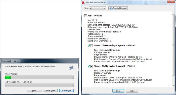
   //Get number of layouts in Dsd file
   int iLayouts = dColl.Count;
   //Specify plot progress dialog values
   using (PlotProgressDialog oProg =
      new PlotProgressDialog(false, iLayouts, true)) {
      	oProg.set_PlotMsgString(PlotMessageIndex.DialogTitle,
         	"Publish Job Progress");
      oProg.set_PlotMsgString(PlotMessageIndex.
         CancelJobButtonMessage, "Cancel Job");
      oProg.set_PlotMsgString(PlotMessageIndex.
         CancelSheetButtonMessage, "Cancel Sheet");
      	oProg.set_PlotMsgString(PlotMessageIndex.
         SheetSetProgressCaption, "Job Progress");
      oProg.set_PlotMsgString(PlotMessageIndex.
         SheetProgressCaption, "Sheet Progress");
      //Set ranges for sheet and job progress
      oProg.UpperPlotProgressRange = 100;
      oProg.LowerPlotProgressRange = 0;
      oProg.UpperSheetProgressRange = 100;
      oProg.LowerSheetProgressRange = 0;
      oProg.IsVisible = true;

      //Publish selected layouts in a multi-sheet pdf file
      Autodesk.AutoCAD.Publishing.Publisher publisher =
         AcadApplication.Publisher;
      PlotConfig plotConfig = Autodesk.AutoCAD.PlottingServices.
         PlotConfigManager.SetCurrentConfig ("DWG To PDF.pc3");
      publisher.PublishDsd(dFile, oProg);
      //Delete temporary Dsd file
      File.Delete(dFile);
   }
   trans.Commit();
}
catch (Autodesk.AutoCAD.Runtime.Exception ex) {
   ed.WriteMessage((System.Environment.NewLine +
      "Problem publishing DSD file. " + ex.Message));
}
Finally, restore the
BackgroundPlotsystem variable to its previous value. That's it!finally { //Restore previous BackgroundPlot setting. AcadApplication.SetSystemVariable("BACKGROUNDPLOT", bkgdPlt); }The dialog box interface that we created for this project is based on the one that we made for the plugin in the Controlling the drawing environment (Should know) recipe. This project requires some additional actions, however. First, the listbox must allow for multiple selections this time, since we may publish more than one layout from a drawing:
using System;
using System.Collections.Generic;
using System.IO;
using System.Linq;
using System.Text;
using System.Windows;
using System.Windows.Controls;
using System.Windows.Data;
using System.Windows.Documents;
using System.Windows.Input;
using System.Windows.Media;
using System.Windows.Media.Imaging;
using System.Windows.Shapes;
using Autodesk.AutoCAD.ApplicationServices;
using Autodesk.AutoCAD.DatabaseServices;
using Autodesk.AutoCAD.EditorInput;
using AcadApp = Autodesk.AutoCAD.ApplicationServices;

namespace Ch7AcadPlugin {
   /// <summary>
   /// Interaction logic for Window1.xaml
   /// </summary>
   public partial class Window1 : Window {
      public static string txtDwgToRead;
      public static string txtSavPdf;
      public static System.Collections.IList lstLayoutNames;

      //Create the dialog
      public Window1() {
         InitializeComponent();
         //Allow multiple selections in listbox
         this.listBoxLayoutsToPublish.SelectionMode =
            System.Windows.Controls.SelectionMode.Multiple;
      }
The
SaveFileDialogandOpenFileDialogcontrols will validate your selection, adding a file extension if necessary. We'll add some code to validate filename entries that were typed into the textboxes.//'Click' event handler for 'OK' button private void okButton_Click(object sender, RoutedEventArgs e) { //Get values from textboxes and listbox if ((txtBoxDwgLocation.Text.Length > 0) && (string.Equals(txtBoxDwgLocation.Text.Substring( txtBoxDwgLocation.Text.Length - 4), ".dwg", StringComparison.OrdinalIgnoreCase) == false)) //Add valid extension if needed txtBoxDwgLocation.Text += ".dwg"; txtDwgToRead = txtBoxDwgLocation.Text; //Get collection of selected layout names lstLayoutNames = listBoxLayoutsToPublish.SelectedItems; if ((txtBoxPdfLocation.Text.Length > 0) && (string.Equals(txtBoxPdfLocation.Text.Substring( txtBoxPdfLocation.Text.Length - 4), ".pdf", StringComparison.OrdinalIgnoreCase) == false)) //Add valid extension if needed txtBoxPdfLocation.Text += ".pdf"; txtSavPdf = txtBoxPdfLocation.Text; this.DialogResult = true; this.Close(); //close the dialog //Call function to publish selected layouts MyCommands.PubLo2Pdf(); } //'Click' event handler for 'Cancel' button private void cancelButton_Click(object sender, RoutedEventArgs e){ this.Close(); //close the dialog }The
OpenFileDialogandSaveFileDialogcontrols can be set to add a default extension when the user types in a filename, rather than selecting a file://'Click' event handler for dwg-to-read 'Browse...' button private void btnDwgLocation_Click(object sender, RoutedEventArgs e){ //Create OpenFileDialog Microsoft.Win32.OpenFileDialog dlg = new Microsoft.Win32.OpenFileDialog(); //Set filter for file extension and default file extension dlg.DefaultExt = ".dwg"; dlg.Filter = "Drawing (.dwg)|*.dwg"; dlg.AddExtension = true; //Display OpenFileDialog Nullable<bool> result = dlg.ShowDialog(); //If file is selected, display file name in the textbox if (result == true) { //Get the document filename from the dialog string fn = dlg.FileName; //Populate textbox with the document filename txtBoxDwgLocation.Text = fn; txtDwgToRead = fn; } } //'Click' event handler for pdf-file 'Browse...' button private void btnPdfLocation_Click(object sender, RoutedEventArgs e){ //Create SaveFileDialog Microsoft.Win32.SaveFileDialog dlg = new Microsoft.Win32.SaveFileDialog(); //Set filter for file extension and default file extension dlg.DefaultExt = ".pdf"; dlg.Filter = "PDF (.pdf)|*.pdf"; dlg.AddExtension = true; //Display SaveFileDialog Nullable<bool> result = dlg.ShowDialog(); //If file is selected, display file name in the textbox if (result == true) { //Get the document filename from the dialog string fn = dlg.FileName; //Populate textbox with the document filename txtBoxPdfLocation.Text = fn; } }In the
Clickevent handler for the Read button, we create the auxiliary or side database, into which we read the selected drawing. The purpose is to populate the listbox with the drawing's layout names://'Click' event handler for 'Read' button private void btnReadDwg_Click(object sender, RoutedEventArgs e) { Document doc = AcadApp.Application.DocumentManager.MdiActiveDocument; Editor ed = doc.Editor; this.listBoxLayoutsToPublish.Items.Clear(); if ((txtBoxDwgLocation.Text.Length > 0) && (string.Equals(txtBoxDwgLocation.Text.Substring( txtBoxDwgLocation.Text.Length - 4), ".dwg", StringComparison.OrdinalIgnoreCase) == false)) //Add valid extension if needed txtBoxDwgLocation.Text += ".dwg"; txtDwgToRead = txtBoxDwgLocation.Text; // Create a side database and try to read the dwg file Database db = new Database(false, true); using (db) { try { db.ReadDwgFile(txtDwgToRead, FileShare.Read, false, ""); } catch (System.Exception) { ed.WriteMessage("\nUnable to read drawing file."); return; } Transaction tr = db.TransactionManager.StartTransaction(); using (tr) { //Get each entry in the layout dictionary DBDictionary loDic = (DBDictionary)tr.GetObject(db.LayoutDictionaryId, OpenMode.ForRead, false); foreach (DBDictionaryEntry entry in loDic) { ObjectId loId = entry.Value; //Open the layout for read Layout lo = (Layout)tr.GetObject(loId, OpenMode.ForRead); //Add the layout name to the listbox this.listBoxLayoutsToPublish.Items.Add(lo.LayoutName); } tr.Commit(); }//end transaction } }We'll also need to add
SelectionChangedevent handlers for the Select layouts listbox and the textboxes where the external drawing and PDF file are specified://'SelectionChanged' event handler for 'Select layouts:' listbox private void listBoxLayoutsToPublish_SelectionChanged(object sender, SelectionChangedEventArgs e) { } //'TextChanged' event handler for 'Specify dwg to read:' textbox private void txtBoxDwgLocation_TextChanged(object sender, TextChangedEventArgs e) { } //'TextChanged' event handler for 'Specify pdf file:' textbox private void txtBoxPdfLocation_TextChanged(object sender, TextChangedEventArgs e) { }
We start here with a UI, similar to the one we made in the Controlling the drawing environment (Should know) recipe. Only this time, we add an OpenFileDialog control to select an external drawing (.dwg) file. We also add a button to read the selected drawing into a temporary database. We iterate through the layout dictionary, grabbing the layout names and adding them to a listbox. Unlike in the Controlling the drawing environment (Should know) recipe, this listbox allows us to select multiple layouts.
Once the layout names are selected, we dismiss the temporary database. Now we create a temporary DSD file, which contains the layout information for each sheet that we'll publish in our PDF file. We also add some captions and range limits for the Publish Job Progress dialog box. AutoCAD reads the temporary DSD file and publishes the multi-sheet PDF. When the job is done, we delete the temporary DSD file.
Software tools address specific needs. In the case of AutoCAD, that means drawing, revising, and publishing. What if we need to perform very elaborate calculations or sorting sequences on our AutoCAD data? It would be great to export our CAD data to another tool (for example, a spreadsheet) to operate on the data. And now we can! In this project, we will export AutoCAD data to MS Excel for processing (using the Excel API).
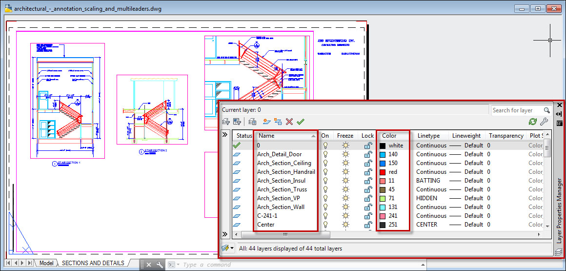
In this project, we'll take a drawing that has several layers and export the layer data to Excel. Once in Excel, we will sort the layer data using two criteria: first, we'll sort alphanumerically by layer color; then, within the range of each color, sort the data by the layer name. To capture the layer data, we'll use the WPF data binding that exists in AutoCAD 2013, the UIBindings.Collections class. One use for this class is to provide information about specific data collections (such as layers) to the AutoCAD Ribbon. We'll use it to collect a partial set of layer data to export to Excel.
As a source of layers, let's use one of the AutoCAD's sample drawings, architectural_-_annotation_scaling_and_multileaders.dwg, which contains 44 layers. In previous releases, these drawings used to ship with AutoCAD. Today, that is no longer the case. Sample drawings are now centrally located. You can access them at: http://www.autodesk.com/autocad-samples. This drawing is found under the heading, AutoCAD 2010 Sample Files.
We will need to grab a couple of references to some Excel assemblies:
using System;
using System.Collections.Generic;
using System.Data;
using System.Diagnostics;
using System.Drawing;
using System.Linq;
using System.Text;
using System.Runtime.InteropServices;
using System.Reflection;
using Microsoft.Office.Interop;
using Microsoft.Office.Tools.Excel;
using Microsoft.VisualBasic;
using Autodesk.AutoCAD.ApplicationServices;
using Autodesk.AutoCAD.DatabaseServices;
using Autodesk.AutoCAD.EditorInput;
using Autodesk.AutoCAD.Geometry;
using Autodesk.AutoCAD.Runtime;
using Excel = Microsoft.Office.Interop.Excel;

// This line is not mandatory, but improves loading performances
[assembly: CommandClass(typeof(Ch8AcadPlugin.MyCommands))]

namespace Ch8AcadPlugin {
    public class MyCommands {

        private Excel.Application app = null;
        private Excel.Workbook workbook = null;
        private Excel.Worksheet worksheet = null;
        private Excel.Range wsrange = null;
In our custom command,
SortLayers, we will create an instance of MS Excel. Then we'll create an array of arrays: nine arrays, one for each of nine layer properties://Create new Excel application, workbook, and worksheet public void createWkBk() { try { app = new Excel.Application(); app.Visible = true; workbook = app.Workbooks.Add(1); worksheet = (Excel.Worksheet)workbook.Sheets[1]; } catch (System.Exception) { Console.Write("Error"); } } //Command to export layer data to MS Excel and then //sort the layers(rows) according to color [CommandMethod("SortLayers")] public void SortLayersByColor() { //Get the active document and database Document doc = Application.DocumentManager.MdiActiveDocument; Database db = doc.Database; Editor ed = doc.Editor; using (Transaction trans = db.TransactionManager.StartTransaction()) { //Create Excel app, workbook, worksheet, range createWkBk(); //Declare array of nine elements, each of which is also //an array string[][] headerAndData = new string[9][];Populate an array for each of the properties we will include in the partial set. The array contains row and column data, cell ranges, font properties, and alignment settings. This information is used to create the column headers:
      //Initialize the nine array elements, each one
      //representing a spreadsheet heading KEY: property, row,
      //column, range begin column, range end column, column
      //merge, bold text?, font size, column width, cell text
      //alignment(Horiz.)
      headerAndData [0] = new string[10] {"Layer Data for: " +
         Application.DocumentManager.MdiActiveDocument.Name,
         "1", "1", "A", "H", "2", "true", "16", "80", "C"};
      headerAndData [1] = new string[10] {"Name", "2", "1",
         "A", "A", "2", "true", "12", "25", "C"};
      headerAndData [2] = new string[10] {"Color", "2", "2",
         "B", "B", "2", "true", "12", "25", "C"};
      headerAndData [3] = new string[10] {"IsOff", "2", "3",
         "C", "C", "2", "true", "12", "25", "C"};
      headerAndData [4] = new string[10] {"IsFrozen", "2", "4",
         "D", "D", "2", "true", "12", "25", "C"};
      headerAndData [5] = new string[10] {"IsLocked", "2", "5",
         "E", "E", "2", "true", "12", "25", "C"};
      headerAndData [6] = new string[10] {"IsPlottable", "2",
         "6", "F", "F", "2", "true", "12", "25", "C"};
      headerAndData [7] = new string[10] {"PlotStyleName", "2",
         "7", "G", "G", "2", "true", "12", "25", "C"};
      headerAndData [8] = new string[10] {"Description", "2",
         "8", "H", "H", "2", "true", "12", "25", "C"};

      //Create spreadsheet headers for dwg file and layer
      //details, then add layer property data
      AddHeadersAndData(headerAndData);

      //Sort layers, first by Color, then by Layer Name
      SortRange();

      //Save the workbook and exit Excel, releasing the
      //COM objects to prevent hanging Excel process
      SaveWB();
   }
}
By reading the array contents, we'll populate the headers in the spreadsheet:
//Create spreadsheet headers for dwg file and layer details,
//and add layer property data
public void AddHeadersAndData(string[][] arr) {
   for (int i = 0; i < arr.Length; i++) {
      for (int j = 0; j < arr[i].Length; j++) {
         //Retrieve the header details
         string head = arr[i][j];
         string propertyName = arr[i][j];
         j++;
         int iRow = Convert.ToInt32(arr[i][j]);
         j++;
         int iCol = Convert.ToInt32(arr[i][j]);
         j++;
         string c1 = arr[i][j];
         j++;
         string c2 = arr[i][j];
         j++;
         int colMrg = Convert.ToInt32(arr[i][j]);
         j++;
         bool bBold = Convert.ToBoolean(arr[i][j]);
         j++;
         int iFont = Convert.ToInt32(arr[i][j]);
         j++;
         int iWidth = Convert.ToInt32(arr[i][j]);
         j++;
         Excel.XlHAlign hAlign = Excel.XlHAlign.xlHAlignCenter;
         if (arr[i][j] == "C") {
            //Horizontally align the header text to the center
            hAlign = Excel.XlHAlign.xlHAlignCenter;
         }
         else if(arr[i][j] == "L") {
            //Horizontally align the header text to the left
            hAlign = Excel.XlHAlign.xlHAlignLeft;
         }
         else if(arr[i][j] == "R") {
            //Horizontally align the header text to the right
            hAlign = Excel.XlHAlign.xlHAlignRight;
         }
         //Write the header rows to the cells
         worksheet.Cells[iRow,iCol] = head;
         wsrange = worksheet.get_Range(c1 + iRow.ToString(),
            c2 + iRow.ToString());
         wsrange.Borders.Color =
            System.Drawing.Color.Black.ToArgb();
         wsrange.Merge(colMrg);
         wsrange.Font.Bold = bBold;
         wsrange.Font.Size = iFont;
         wsrange.ColumnWidth = iWidth;
         wsrange.HorizontalAlignment = hAlign;
For each layer property that we list in the header, add corresponding layer data below the header:
         if (iRow > 1) {
            //If iRow is below the main heading, add Layer
            //data under each Layer Property heading
            iRow = 3;
            //Iterate through the layers in the AutoCAD WPF
            //data binding UIBindings.Collections class
            Autodesk.AutoCAD.Windows.Data.DataItemCollection
               dataItemCollection =
                  Application.UIBindings.Collections.Layers;
            foreach (System.ComponentModel.ICustomTypeDescriptor
               desc in dataItemCollection) {
               //Get the desired layer table record
               //properties and write them to the cells
               dynamic propertyValue =
               desc.GetProperties()[propertyName].GetValue(desc);
               worksheet.Cells[iRow, iCol] =
                  propertyValue.ToString();
               wsrange = worksheet.get_Range(c1 + iRow.ToString(),
                  c2 + iRow.ToString());
Add a border around each cell containing layer data and align the text to the left:
                  //Add a border around the cell
                  wsrange.Borders.Color =
                     System.Drawing.Color.Black.ToArgb();
                  wsrange.NumberFormat = "";
                  //Horizontally align the data text to the left
                  wsrange.HorizontalAlignment =
                     Excel.XlHAlign.xlHAlignLeft;
                  iRow = iRow + 1;
               }
            }
         }
      }
   }
Sort the layer data in Excel, first sorting by the color name, and then by layer name:
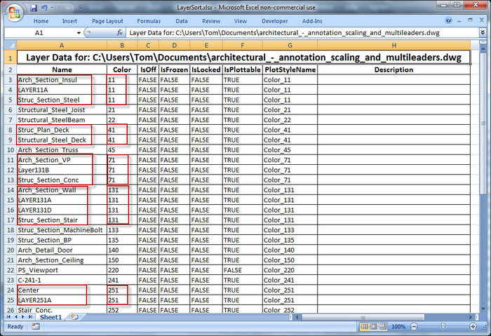
   //Sort spreadsheet range data, first by layer Color property,
   //and then by layer Name
   public void SortRange() {
      Excel.Range oRng = worksheet.get_Range("A3", "K50");
      oRng.Sort(oRng.Columns[2, Type.Missing],
         Excel.XlSortOrder.xlAscending, oRng.Columns[1,
         Type.Missing], Type.Missing,
         Excel.XlSortOrder.xlAscending, Type.Missing,
         Excel.XlSortOrder.xlAscending, Excel.XlYesNoGuess.xlNo,
            Type.Missing, Type.Missing,
            Excel.XlSortOrientation.xlSortColumns,
            Excel.XlSortMethod.xlPinYin,
            Excel.XlSortDataOption.xlSortNormal,
            Excel.XlSortDataOption.xlSortNormal,
            Excel.XlSortDataOption.xlSortNormal);
   }
Save and exit from Excel, and release COM objects:
   //Save the workbook and exit Excel, releasing the
   //COM objects to prevent hanging Excel process
   public void SaveWB() {
      workbook.Close();
      app.Quit();
	   System.Runtime.InteropServices.Marshal.
         ReleaseComObject(wsrange);
      System.Runtime.InteropServices.Marshal.
         ReleaseComObject(worksheet);
      System.Runtime.InteropServices.Marshal.
         ReleaseComObject(workbook);
      System.Runtime.InteropServices.Marshal.
         ReleaseComObject(app);
      wsrange = null;
      worksheet = null;
      workbook = null;
      app = null;
   }
The resulting data, sorted by color and then by name, looks like this:
The UIBindings.Collections class contains common AutoCAD data collections, such as layer. We could obtain every layer property that is normally visible in the Layer Properties Manager dialog. For our purposes, we use only a subset of the available layer data.
The code is fairly straightforward, and some of it covers what must be familiar territory by now: getting the AutoCAD document, database, and editor. It may be beneficial to read up on the Excel API to get a better understanding of writing to cells, sorting the worksheet ranges, and so on.
No matter what API we use to communicate between AutoCAD and Excel, we may run into an issue where we have already saved and quit Excel, but the Excel process hangs. Subsequent Excel access through the API may result in unexpected behavior. It is necessary to release all Excel COM objects. The obvious ones are the apps, workbooks, and worksheets. Others that are often overlooked include worksheet collections and the worksheet range objects.
In this book, we only scratch the surface of using Microsoft's WPF, creating simple interfaces and hooking into one of AutoCAD's data collections. If you have more than a passing interest in learning how to leverage WPF in AutoCAD, it is strongly recommended to take a look at Fenton Webb's presentations on the subject (go to http://adndevblog.typepad.com/autocad/2013/05/api-webcast-archive.html to download the two presentations). Fenton is a long-time member of Autodesk's Developer Technical Services, and possesses a deep knowledge of the AutoCAD APIs. This project was inspired by one of Fenton's blog postings.
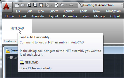
Using the .NET API, we'll add a custom button to the AutoCAD ribbon interface. At this point, I've grown tired of typing NETLOAD every time I want to load a .NET assembly. Instead, I want to define a custom button on the ribbon that I can click on and execute the NETLOAD command.
There are two common approaches to customizing the AutoCAD ribbon. One involves creating a partial CUIX file, and the other uses the .NET API to modify the ribbon at runtime. This being a book about the AutoCAD .NET API, we will focus on the latter.
First, let's designate
ID_CUSTOMCMDSas the internal name for our custom ribbon tab, and add some methods for adding and removing the custom tab. In this example, our tab will contain a panel which holds a single custom button. The button will include a two-level tooltip:using System; using Autodesk.AutoCAD.Runtime; using Autodesk.AutoCAD.Windows; using Autodesk.Windows; using Autodesk.AutoCAD.EditorInput; using System.Collections.Generic; // This line is not mandatory, but improves loading performances [assembly: CommandClass(typeof(Ch9AcadPlugin.MyCommands))] namespace Ch9AcadPlugin { public class MyCommands { //Declare the custom tab name here private const String TAB_ID = "ID_CUSTOMCMDS"; public void delRibbon() { Autodesk.Windows.RibbonControl rbnCtrl = Autodesk.AutoCAD.Ribbon.RibbonServices. RibbonPaletteSet.RibbonControl; //Check for the custom ribbon tab and delete for (int i = 0; i < rbnCtrl.Tabs.Count; i++) { if (rbnCtrl.Tabs[i].Id.Equals(TAB_ID)) { rbnCtrl.Tabs.Remove(rbnCtrl.Tabs[i]); return; } } } //Add the custom ribbon tab and panel public void addRibbon() { Autodesk.Windows.RibbonControl rbnCtrl = Autodesk.AutoCAD.Ribbon.RibbonServices. RibbonPaletteSet.RibbonControl; //Add custom ribbon tab RibbonTab rbnTab = new RibbonTab(); rbnTab.Title = "Custom commands"; rbnTab.Id = TAB_ID; rbnCtrl.Tabs.Add(rbnTab); //Add custom ribbon panel addRbnPnl(rbnTab); //Set the custom ribbon tab active rbnTab.IsActive = true; }Next, we'll add the ribbon panel, button, and tooltip, in that order. Label the panel Custom commands:
      //Add the custom ribbon panel, button, and tooltip
      //for the built-in NETLOAD command
      private void addRbnPnl(RibbonTab rbnTab) {
         //Add ribbon panel source
         Autodesk.Windows.RibbonPanelSource rbnPnlSrc =
            new RibbonPanelSource();
         rbnPnlSrc.Title = "Custom commands";
         //Add custom ribbon panel
         RibbonPanel rbnPnl = new RibbonPanel();
         rbnPnl.Source = rbnPnlSrc;
         rbnTab.Panels.Add(rbnPnl);
Add a button to the panel. Label the button to read NETLOAD, and set the
CommandParameterproperty toNETLOADas well://Add custom ribbon button Autodesk.Windows.RibbonButton rbnBtn = new RibbonButton(); rbnBtn.Text = "NETLOAD"; rbnBtn.CommandParameter = "NETLOAD "; rbnBtn.ShowText = true; rbnBtn.CommandHandler = new AdskCommandHandler();Add an expanded tooltip to the button. This tooltip has two levels of content. One which displays immediately when you hover with the cursor, and one which displays after a brief delay:
         //Add custom ribbon tooltip
         Autodesk.Windows.RibbonToolTip rbnTT =
            new RibbonToolTip();
         rbnTT.Command = "NETLOAD";
         rbnTT.Title = "Load a .NET assembly";
         rbnTT.Content =
            "Command to load a .NET assembly in AutoCAD";
         rbnTT.ExpandedContent =
            "In the dialog box, navigate to the .NET assembly you
            want to load and select it.";
         rbnBtn.ToolTip = rbnTT;
         rbnPnlSrc.Items.Add(rbnBtn);
      }
Now add a method to register the assembly, so the custom button persists the next time you start AutoCAD:
//Register the assembly
public void AppReg() {
   //AutoCAD registry key
   Microsoft.Win32.RegistryKey regKeyAcad =
      Microsoft.Win32.Registry.CurrentUser.OpenSubKey(
         Autodesk.AutoCAD.DatabaseServices.
         HostApplicationServices.Current.
         UserRegistryProductRootKey);
   //AutoCAD Application key
   Microsoft.Win32.RegistryKey regKeyAcadApp =
      regKeyAcad.OpenSubKey("Applications", true);
   //Check whether app is registered
   string appName =
      System.Reflection.Assembly.GetExecutingAssembly().
      GetName().Name;
   String[] subKeys = regKeyAcadApp.GetSubKeyNames();
   foreach (String subKey in subKeys) {
      if (subKey.Equals(appName)) {
         regKeyAcadApp.Close();
         return;
      }
   }
   //Get app location and full name
   string appPath = System.Reflection.Assembly.
      GetExecutingAssembly().Location;
   string appFullName = System.Reflection.Assembly.
      GetExecutingAssembly().GetName().FullName;
   //Add registry key for addin
   Microsoft.Win32.RegistryKey regKeyAddin =
      regKeyAcadApp.CreateSubKey(appName);
   regKeyAddin.SetValue("DESCRIPTION", appFullName,
      Microsoft.Win32.RegistryValueKind.String);
	regKeyAddin.SetValue("LOADCTRLS", 14,
      Microsoft.Win32.RegistryValueKind.DWord);
   regKeyAddin.SetValue("LOADER", appPath,
      Microsoft.Win32.RegistryValueKind.String);
   regKeyAddin.SetValue("MANAGED", 1,
      Microsoft.Win32.RegistryValueKind.DWord);
   regKeyAcadApp.Close();
}
Likewise, add a method to unregister the assembly. Make this one a command method, to allow us to unregister it from the command line:
//Command to unregister the assembly
[CommandMethod("AppUnreg")]
public void AppUnreg() {
   //AutoCAD registry key
   Microsoft.Win32.RegistryKey acadKey =
       Microsoft.Win32.Registry.CurrentUser.OpenSubKey(
       Autodesk.AutoCAD.DatabaseServices.
       HostApplicationServices.Current.
       UserRegistryProductRootKey);
   //AutoCAD Application key
   Microsoft.Win32.RegistryKey acadAppKey =
       acadKey.OpenSubKey("Applications", true);
   //Delete registry key
   string appName = System.Reflection.Assembly.
       GetExecutingAssembly().GetName().Name;
   acadAppKey.DeleteSubKeyTree(appName);
   acadAppKey.Close();
}
Add a handler to execute a command when the button is clicked:
public class AdskCommandHandler : System.Windows.Input.ICommand {
   public bool CanExecute(object parameter) {
      return true;
   }
   public event EventHandler CanExecuteChanged;

   public void Execute(object parameter) {
      RibbonButton rbnBtn = parameter as RibbonButton;
      if (rbnBtn != null) {
      //Execute command specified in ribbon button parameter
         Autodesk.AutoCAD.ApplicationServices.
            Application.DocumentManager.MdiActiveDocument.
            SendStringToExecute((String)rbnBtn.CommandParameter,
            true, false, true);
      }
   }
}
Finally, add an event handler to notify us when the ribbon becomes initialized, so we can add our custom tab:
using System;
using Autodesk.AutoCAD.Runtime;
using Autodesk.AutoCAD.ApplicationServices;
using Autodesk.AutoCAD.DatabaseServices;
using Autodesk.AutoCAD.Geometry;
using Autodesk.AutoCAD.EditorInput;
using Autodesk.Windows;
// This line is not mandatory, but improves loading performances
[assembly: ExtensionApplication(typeof(Ch9AcadPlugin.MyPlugin))]
namespace Ch9AcadPlugin {
   public class MyPlugin : IExtensionApplication {
      void IExtensionApplication.Initialize() {
         if (Autodesk.Windows.ComponentManager.Ribbon == null) {
            //Load custom ribbon on startup. Register
            //ItemInitialized event for when ribbon becomes
            //available
            Autodesk.Windows.ComponentManager.ItemInitialized +=
               new EventHandler<RibbonItemEventArgs>
               (ComponentManager_ItemInitialized);
         }
         else {
            //If ribbon control is available, add custom ribbon
            MyCommands MyCmds = new MyCommands();
            MyCmds.AppReg();
            MyCmds.addRibbon();
         }
      }
      void ComponentManager_ItemInitialized(object sender,
         RibbonItemEventArgs e) {
         //Is ribbon available?
         if (Autodesk.Windows.ComponentManager.Ribbon != null) {
            //If so, add custom ribbon
            MyCommands MyCmds = new MyCommands();
            MyCmds.addRibbon();
            //Delete ItemInitialized event handler –
            //no longer needed
            Autodesk.Windows.ComponentManager.ItemInitialized -=
               new EventHandler<RibbonItemEventArgs>
               (ComponentManager_ItemInitialized);
         }
      }
      void IExtensionApplication.Terminate() {
         // Do plug-in application clean up here
      }
   }
}
We first check to see whether the AutoCAD ribbon has been initialized before adding our custom tab, button, and so on. We then define a custom tab, panel, button, and tooltip. Then, when the user clicks the button, a handler executes the command that we specified in the button's CommandParameter property.
Besides .NET, AutoCAD has another API, Autolisp, and it's been around for decades (your CAD department may already rely on several Autolisp programs)! Learn how the AutoCAD .NET API can work with Autolisp.
Define a LISP function the same way we've defined commands. Use the LispFunction attribute instead of the CommandMethod attribute.
In an Autolisp program, define a function which, when executed, will call the method that is tagged with the
LispFunctionattribute in our .NET project. In this case, we'll define a LispFunction(fizzbuzz), named for the notorious software development interview question. When(fizzbuzz)is called from Autolisp, it will call the .NET methodfizzBuzz_net:using System; using System.Collections.Generic; using Autodesk.AutoCAD.ApplicationServices; using Autodesk.AutoCAD.DatabaseServices; using Autodesk.AutoCAD.EditorInput; using Autodesk.AutoCAD.Runtime; using Autodesk.AutoCAD.Windows; using Autodesk.Windows; // This line is not mandatory, but improves loading performances [assembly: CommandClass(typeof(Ch10AcadPlugin.MyCommands))] namespace Ch10AcadPlugin { public class MyCommands { //Lisp function to call .NET fizzbuzz function [LispFunction("fizzbuzz")] static public ResultBuffer fizzBuzz_net(ResultBuffer args) { Editor ed = default(Editor); ed = Autodesk.AutoCAD.ApplicationServices.Application. DocumentManager.MdiActiveDocument.Editor; //Ensure there are arguments passed in if (args == null) { ed.WriteMessage("No arguments" + System.Environment.NewLine); return args; } else { Array argsArray = null; argsArray = args.AsArray();Use a ResultBuffer to pass arguments to
fizzBuzz_net. Put the arguments in an array:if (argsArray.Length > 0) { string myArg1 = ""; //Get the arguments that were passed in TypedValue myTypeVal = default(TypedValue); myTypeVal = (TypedValue)argsArray.GetValue(0); myArg1 = (string)myTypeVal.Value; for (int i = 1; i <= 100; i++) { if (i % 15 == 0) { //Not a multiple of 3 and 5 ed.WriteMessage(System.Environment.NewLine + "FizzBuzz"); } else if (i % 3 == 0) { //Not a multiple of 3 ed.WriteMessage(System.Environment.NewLine + "Fizz"); } else if (i % 5 == 0) { //Not a multiple of 5 ed.WriteMessage(System.Environment.NewLine + "Buzz"); } else { //Not a multiple of 3 or 5 ed.WriteMessage(System.Environment.NewLine + i.ToString()); } }Modify the contents of the
ResultBufferand pass it back to the calling function://Modify the string value from the Result Buffer myArg1 += " completed!"; // Package data to send back to calling lisp //function ResultBuffer resBuf = default(ResultBuffer); resBuf = new ResultBuffer(new TypedValue( Convert.ToInt32(LispDataType.Text), myArg1)); return resBuf; } else { ed.WriteMessage("Not enough arguments" + System.Environment.NewLine); return args; } } } } }
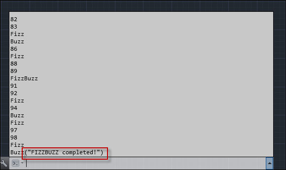
Enter a simple Autolisp function at the command line to call the .NET LispFunction.

We defined a .NET LispFunction to respond to an Autolisp function (fizzbuzz arg). In Autolisp syntax, the function name comes immediately after the opening parenthesis.
When we type in (fizzbuzz "FIZZBUZZ"), we are calling a function named fizzbuzz and passing in a string argument FIZZBUZZ. The .NET LispFunction fizzBuzz_net expects a single ResultBuffer argument. We carry out the actual fizzbuzz sequence in our .NET function. The string argument that we passed in is also modified by our .NET code, and returned (in a ResultBuffer) back to the calling Autolisp function. That's why we see the modified FIZZBUZZ string in the command prompt.
AutoCAD fires event notifications as a result of specific actions and states. These notifications provide crucial information to our custom applications, allowing them to react in real time to changes in your AutoCAD drawing.
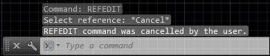
This is a simple example that responds to AutoCAD commands being cancelled. The name of the cancelled command is displayed at the command prompt.
First, we add two commands to turn the event handler monitoring on or off for the AutoCAD document
CommandCancelledevent:using System; using Autodesk.AutoCAD.Runtime; using Autodesk.AutoCAD.ApplicationServices; using Autodesk.AutoCAD.EditorInput; // This line is not mandatory, but improves loading performances [assembly: CommandClass(typeof(Ch11AcadPlugin.MyCommands))] namespace Ch11AcadPlugin { public class MyCommands { [CommandMethod("EventON")] public void EventON() { Document doc = Application.DocumentManager.MdiActiveDocument; //Add the event handler doc.CommandCancelled += new CommandEventHandler(doc_CommandCancelled); } [CommandMethod("EventOFF")] public void EventOFF() { Document doc = Application.DocumentManager.MdiActiveDocument; //Remove the event handler doc.CommandCancelled -= new CommandEventHandler(doc_CommandCancelled); }Now we will add the actual event handler functionality. We will use the
WriteMessage()method to display the cancelled command name:public static void doc_CommandCancelled(object sender, CommandEventArgs e) { Document doc = Application.DocumentManager.MdiActiveDocument; Editor ed = doc.Editor; ed.WriteMessage(string.Format( "\n{0} command was cancelled by the user.\n", e.GlobalCommandName)); } } }