


Welcome to FreeCAD [How-to]. This book will provide an introduction to the organization and versatility of this open source application. The recipes described in this book will introduce most of the concepts used throughout FreeCAD so that knowledge gained in one area will help you explore the other areas more efficiently.
FreeCAD is a general purpose modeling tool aimed at the engineering world. Unlike other modeling tools such as Blender or Maya, which are designed for animators and artists, FreeCAD puts heavy emphasis on parametric, feature-based design of three dimensional solids.
A great deal of foresight and planning has gone into the underlying technology of FreeCAD. The result is a tool that is powerful, easy to use, and easy to extend with the powerful scripting language Python.
This first part of this book will help you get familiar with the FreeCAD interface and philosophy. We'll look at a couple of specific techniques for modeling objects. The later recipes will focus more on using Python to automate and extend FreeCAD.
This recipe will describe the options available for installing FreeCAD on the three major platforms (Windows, Mac, and Linux). It will briefly cover the steps for installation of a stable release version.
FreeCAD is still under heavy development. Stable releases are provided periodically that are tested and debugged. These releases will lack the most current features and may not match many of the recipes described in this book.
Detailed instructions are provided on the FreeCAD site for installation on all three platforms along with removal and troubleshooting information.
For most casual users, the stable version binaries are the best place to start learning FreeCAD.
Start by visiting the FreeCAD site at http://free-cad.sourceforge.net/.
The main page of the FreeCAD site has a panel with download links for the current stable release.

For Windows, the stable release is provided as a 32-bit Microsoft Installer application (
.msifile). Download the file to your computer and double-click it to run the installation program.The Linux (Ubuntu) link will direct you to a personal package archive (
PPA). The packages here are for Ubuntu but should work on any recent Debian derived distribution. Both 32 and 64 bit versions are available through the PPA. Add the PPA to your repository manager and install it like any other application. FreeCAD is also available in the main Ubuntu repository, but this version is outdated and should be avoided.Mac OS X (Lion) is supported with a 64-bit installer package. The installer is distributed in a disk image. Download the disk image file. Mount it and run the Install FreeCAD package. In the past, Mac OS X packaging was supported by only a small team and packages were not always up to date. OS X users are encouraged to consider building from source.
FreeCAD's development pace is very fast. New features and improvements are appearing almost daily in the unstable and development branches of the source code. After you've explored the basics, you may wish to explore features not yet available in the stable version. Let's look at some of the other installation options.
If you are using Linux and are willing to accept the risk of broken features and occasional crashes, you can install one of the daily builds. These are generated automatically by build scripts each day and consequently have had no formal testing. The daily build contains the most recent features and bug fixes committed to the source code by the developers.
Daily builds aren't available for Windows but an unstable binary installer is periodically built. Download it from http://sourceforge.net/projects/free-cad/files/FreeCAD%20Windows/.
Detailed instructions for building FreeCAD from source is beyond the scope of a How-to book, but an overview of the major steps may help:
Meet the prerequisites: You'll need a compiler and all the dependency libraries. FreeCAD has a long list of dependencies and getting them all in place can be a chore. This is much easier on a Linux computer since most or all of the dependencies can be downloaded from the software manager.
For Windows, the FreeCAD site also provides a libpack download to simplify the dependency requirements.
Obtain the source code: FreeCAD source is maintained in a Git repository available at git://free-cad.git.sourceforge.net/gitroot/free-cad/free-cad.
Compiling: The specifics steps for compiling vary from platform to platform but are generally simple once the source and dependencies are in place. Study the page for your platform on the FreeCAD site.
The FreeCAD site also maintains a list of alternate builds. These are binary installations that are created and maintained by people and organizations outside the FreeCAD project. They may include custom features or may be optimized for specific operating systems. At the time of writing, there were third-party builds for OpenSuse, Fedora, Slackware, ArchLinux, Gentoo, and others.
FreeCAD is designed to be flexible, extensible, and task oriented.
The core functionality is divided into workbenches. Each workbench gathers the most frequently used tools for a particular task. This recipe will guide you through the FreeCAD user interface and introduce some concepts that are common across all workbenches.
Launch FreeCAD and orient yourself with the screenshot and the names of the major parts of the interface. The images and examples in this book are from a 0.13 development snapshot.
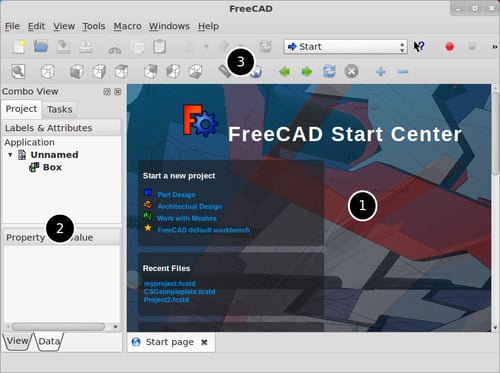
The default view is Start page—an embedded browser showing interesting video links, examples, and other news.
The user interface is divided into three main areas:
The 3D area allows you to see and navigate around your design in space.
The combo view shows a hierarchical view of the project or the state of the current task.
The tool bars and workbench switcher gives access to the various tools.
Open a new document by clicking on the menu File | New. The 3D view will switch to show an empty space. In the default orientation the camera position is looking down onto a plane defined by the X and Y axes. The Z axis is pointed directly at the camera. A coordinate indicator in the corner helps you orient yourself in the 3D space.

Click on the workbench switcher and select the Part workbench. Then click on the Create a box solid icon to insert a cube into the project.
You can have multiple projects open at the same time. You can also open multiple views of the same project. Open a second view of the project by clicking on the menu View | Create new view. You can switch views with the tabs below the 3D window or you can tile the views to have multiple perspectives at once. In this following screenshot, two projects are open, each with two views:

You can change the view of your project by panning, rotating, and zooming. Select objects by clicking on them to change their properties. The specific mouse and keyboard commands for doing this are called "navigation styles". FreeCAD supports four styles by default: Inventor, CAD, Blender, and Touchpad.
You can change the style used in the current view by right-clicking on the 3D canvas.

Changing the style through the Edit | Preferences menu will change the style for all views currently open and set the selection as the default for new views. The default style, CAD navigation, is unintuitive for some users since it requires clicking both the left and center mouse buttons at the same time to rotate. The Mouse... button in the Display preferences will show which button combinations perform each action.
Select the box and tap the space bar to toggle the object visibility property. Visibility is one of many properties of any object on screen. With the box still selected, examine the lower part of the combo-view. The properties of the selected object are shown on the two tabs (View and Data).
Click on the Measure distance icon, and then click two points on the box in the 3D window. A dimension will be shown and a distance object will be added to the tree.

You can select the distance object in the tree and explore its properties.
As the project complexity grows, you may need to perform an action on multiple objects at the same time. Select multiple objects by holding the Ctrl key while selecting with the mouse.
The View/Data tabs reflect a deep design characteristic of FreeCAD. The data necessary to construct the object (size, type, placement, and rotation) is separated from the data needed to show it on screen (color, line style, visibility, and transparency).
Most operations in FreeCAD are non-destructive and result in new objects being added to the project tree. Each new object has its own View and Data tabs and preserves its relationship to its simple precursor. This makes it possible to delete the later objects and revert to the simpler object if needed.
As objects are added and modified, they are organized in the combo-view tree in a hierarchical way. Generally, the last child object is displayed and parent objects are hidden automatically.
FreeCAD uses the term "view" to refer to several related concepts.
Eight default views are provided with icons in the tool bar to make it easy to position the project on the screen. These views are actually orientations of your work and shouldn't be confused with the view windows described previously.
The term view also refers to the camera projection type: orthographic or perspective.
You can preserve a favorite orientation of your work by freezing it (Shift+F). This adds a menu item for the frozen view to let you easily return to this orientation later.
Constructive Solid Geometry (CSG) is a modeling technique that combines primitive solids with Boolean operations to create more complex shapes. FreeCAD's CSG tools are found on the Part workbench.
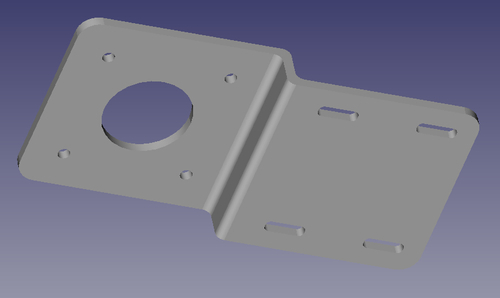
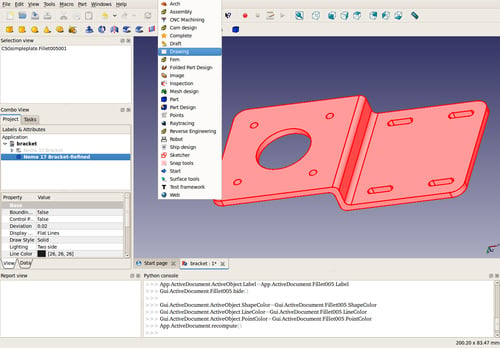
This recipe will use the Part workbench to model a simple part—an offset mounting bracket for a NEMA 17 stepping motor.
Create a new empty document and orient the view to the top using the Set to top view top-view icon or by pressing the number 2. Use the Workbench Changer to switch to the Part workbench.
Model the bent metal plate by adding and positioning three box solids. Add the first box to the drawing, and select its node in the project tree. Switch to the Data tab and edit the properties to make it 2.5 x 50 x 50 mm (height, length, width).
Create a second box with the same dimensions but edit the placement to move the box 50 mm in the X direction and 10 mm in the Z direction. This will place the second cube next to the first and shifted upward.
Add a third cube to connect them. Make its dimensions 10 x 2.5 x 50 mm and shift its placement 50 mm in the X direction.
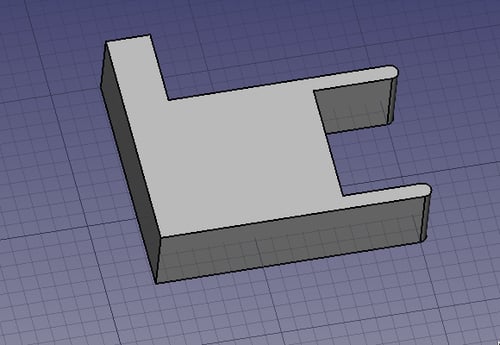
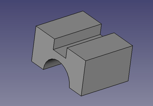
If you rotate your view slightly, your three solids should look like the following figure:

Next we'll create the slots. FreeCAD doesn't have a slot feature so we'll make a solid in the shape of the hole we want. Later, we'll subtract it from the plate to create the hole.
Add another box and set its dimensions to 10 x 10 x 3 mm.
We want the slot to have rounded ends so we will fillet the box. Select the box and press the menu Part | Fillet.
The combo view will switch to the Tasks panel and show the fillet options. You can use this to refine your edge selection and set the radius of the fillet. For our example, select Edge1, Edge3, Edge5, and Edge7. We used a value of 1 for the radius. Clicking on the OK button will apply the change. If you make a mistake, double-click the fillet object in the tree to change the properties and try again.
Once the cube looks right, select it and duplicate it with the menu item Edit | Duplicate selection. Repeat this twice more so that we have a total of four fillet objects. Select each one and change its placement properties to move it into position on the raised part of the plate. The position is up to you. Just make sure the fillet objects completely penetrate the plate.
Now add five cylinders for the holes. Change their placement and radius properties. The center hole is 22.5 mm and the small screw holes are 2.5 mm.
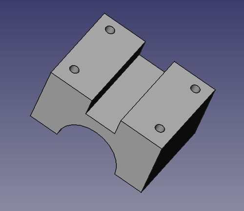
With all the solids added to the project, it should like the following image:

We're almost ready to subtract the cylinders and slots from our base plate, but we first need to clean things up a bit. In the project tree, select all of the cylinders and fillet objects. With all of them selected, click on the Make a union of several shapes icon:

Now select the three boxes for our base plate and repeat the operation, fusing them into a single object.
You should now have two fusion objects in the tree, one for the base plate and one for the holes that will be cut from it. First select the base plate fusion, and then with Ctrl held down, select the other. Click on the Make a cut of two shapes icon:

The order in which you select the objects is important. The first object will be cut by the second. If all goes well, you will have an object that looks almost like the image at the beginning of the recipe.
To finish it off, we've applied another round of fillets to the corners of the plate and to the corners of the bend. The complete object should look like the image at the beginning of this recipe.
Union operations add objects together. The solids don't have to be touching or overlapping. After a union, they will have a single location and orientation.
A difference Boolean cuts the first object with the second. If the two objects don't overlap, the original object will be unaffected.
An intersection eliminates everything except the area where the original two objects overlapped.
After any of these operations, a new object is created and the original items become its hidden children. You can delete the parent node and toggle the original object visible to get back to where you were. Objects such as fillet and chamfer can be double-clicked to reopen the dialog that created them and adjust the options.
Macros are commands that represent a series of commands or key strokes and can take the drudgery out of repetitive tasks. Macro recording can be used to automate tasks that don't warrant full blown script programming. This recipe will cover the steps required to record, edit, and run a macro.
Press the red record button shown in the following screenshot:

The macro recording dialog box will pop up. Give your macro a name and save it:

Perform the tasks that you want recorded. You can create a macro of whatever you normally do in FreeCAD. Macros that deal with simple part creation are easiest to start with. Try creating a box in the Part workbench and change its width to 20 mm.
When you are done recording the tasks, press the green button to stop recording:

Run your macro by selecting the button that looks like a sketch pad:

Select the name of the macro that you created and click on Execute:

In FreeCAD, macros are
just a step-by-step representation of the commands that are saved as a Python script, with a FreeCAD macro file extension *.FCMacro. As you perform tasks in FreeCAD, they have a corresponding Python command that is running in the background. A FreeCAD macro just captures those commands and saves them into a file that you can reuse.
If you have problems saving macros, it could be because of a setting in macro preferences for FreeCAD. Open general preferences by clicking on Edit | Preferences | General and then click on the Macro tab. Under Macro recording settings the Macro path should have a valid path to a file directory in it. If it doesn't, click on the button to the right of it and correct it with a valid directory name.
Most FreeCAD commands can be accessed with macros and Python scripting.
Macros actually record Python instructions as they are executed. We also have the ability to read and edit them later. Open our new macro with the Edit button in the macro dialog. This will open our macro in FreeCAD's built-in macro editor. The following is our code:
# Macro Begin: /home/freecad/10x10x20mm box.FCMacro ++
import FreeCAD
import Part

#Gui.activateWorkbench("PartWorkbench")
App.ActiveDocument.addObject("Part::Box","Box")
#App.ActiveDocument.recompute()
#Gui.SendMsgToActiveView("ViewFit")
FreeCAD.getDocument("Unnamed").getObject("Box").Width = 20.00

# Macro End: /home/freecad/10x10x20mm box.FCMacro ++
Note
Downloading the example code
You can download the example code files for all Packt books you have purchased from your account at http://www.PacktPub.com. If you purchased this book elsewhere, you can visit http://www.PacktPub.com/support and register to have the files e-mailed directly to you.
The lines that begin with # are not executed by FreeCAD; they are Python comments. Comments help us understand what is happening in the code. The only lines of code that are actually executed are as follows:
import FreeCAD
import Part

App.ActiveDocument.addObject("Part::Box","Box")
FreeCAD.getDocument("Unnamed").getObject("Box").Width = 20.00
The statements that start with import open some major modules that are needed for our macro to be able to function. import Part lets us make geometric objects such as boxes, cylinders, spheres, and a lot more. App.ActiveDocument.addObject("Part::Box","Box") actually creates the box.
You can edit macros to do things that they didn't do originally, while they were being recorded. Open the macro in the built-in FreeCAD editor by pressing the button that looks like a text edit pad. Select your macro and then select the Edit button. You could change the values of parameters for many different objects. In our example macro, you could change the following two lines to have a different name and length:
App.ActiveDocument.addObject("Part::Box","newbox")
FreeCAD.getDocument("Unnamed").getObject("newbox").Width=20.5
Save your changes by selecting File | Save in the top menu. Then you can press the green playback icon to try out your altered macro:

Creating and editing macros is a good way of learning how to use Python within FreeCAD. Open your macros in the editor and play with them by changing different parameters and rerun them.
To learn more about the Python programming language, go to http://docs.python.org/tutorial.
Many 3D designs begin as two dimensional drawings that are extruded or rotated into the third dimension. For example, a two dimensional square can be extruded into a three dimensional cube. The Draft workbench provides tools for working with 2D geometry.
In this recipe, we'll draw and edit a 2D profile of a part. In a later recipe, we'll rotate this profile to create a 3D model of a timing pulley.
Start a new project and switch to the Draft workbench. Make sure your view is set to top.
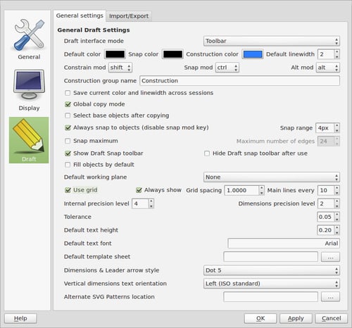
Change your draft preferences to make it easier to snap to the grid. Set the Grid spacing value to 1.000 and the Main lines every value to 10. Set the Snap range to about 4px.
Select the wire tool. Deselect the Relative checkbox. Points of a wire can be added by clicking the canvas or manually by keying in coordinates. Manually enter the first point at X = 3.175, Y = -5, and Z = 0. You can Tab from field to field and hit Enter on Z to create the point.
Continue adding a second point at X = 3.175, Y = 10, Z = -0.
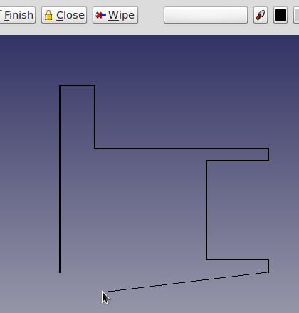
Enter the remaining points working clockwise around until your wire looks like the following image. The remaining points can be added by clicking the canvas, and snapping to the grid if you prefer. Holding the Shift key will force new segments to be orthogonal.
When you have entered the last point but before returning to the starting point, click on Close to automatically close the wire and exit the tool:
Before we can edit any part of the wire we have to explode it into a collection of edges. Select the wire in the project tree. Select the Draft menu and click on the Downgrade button three times.
We'll replace the square edge of the rim with a arc. Make sure that midpoint and endpoint are enabled on the snapping toolbar. Use the arc tool and draw a curve on the rim.

Repeat for the other rim, then delete the old straight edges.
Select all the edges in the tree. Select the Draft menu and click on the Upgrade button to rejoin them into a wire.
Complex topological shapes are built up from more simple geometric objects such as lines, circles, and arcs. For example, an edge can be made from a line connecting two vertices, each of which is a just a point in space. An edge can also be an arc or a circle. When multiple edges are connected end-to-end they become a wire. A closed wire can be upgraded to a face, and if a collection of faces fully encloses a volume it is a solid. If a group of faces doesn't fully enclose the space (that is, one or more faces are missing) it is called a shell.
The Draft workbench provides tools for directly creating, modifying, and converting between these data types.
In addition to the tools for creating and modifying 2D geometry, recent versions of the Draft workbench have a couple of powerful and useful features.
The array tool creates arrays of individual objects. Polar arrays are useful for creating bolt circles and gears. Ortho arrays create grid-like arrangements.

Select the object to be duplicated and click on the array tool. Then adjust the properties of the array in the Data tab. These include the number of copies, rotation center, and array type.
A sketch is another way of drawing 2D data in FreeCAD, which we'll be looking at in more detail in a later recipe. Sketches and drafts serve different purposes but it's sometimes desirable to convert between them. The Draft workbench has a tool for doing this conversion. Be aware that sketch-specific data will be lost when it's converted to a draft.
2D drawings are converted into 3D models either by extruding them along an axis, or by rotating them around an axis.
Use the Draft workbench to draw a closed profile of a part. For our example, we're using the timing pulley profile from the Modeling a simple part with the Draft workbench (Must know) recipe.
Switch to the Draft workbench.
Select the wire and click on the Upgrade button to convert it to a face.
Press the Revoke a selected shape button:

In the Revolve dialog, select the shape to rotate.
Select the axis around which to revolve. For our example, use the Y axis. Leave the other settings unchanged and click on OK.
The revolved object is added to the project.

FreeCAD has two kinds of wire objects. Draft wires, called dwire in later versions, have additional features and properties on the Data tab. The wire used in our example contains arcs and is a regular wire. If you were to rotate the wire without upgrading it to a face first, the result you would see on screen would look exactly the same. However, the object would be a hollow shell. This can cause problems if you do additional Boolean operations. By rotating a face instead of a wire, the area swept out by the rotation is a solid.
Extruding an object works similarly. A shape is selected and parameters are given for the direction and distance to extrude. Applying an extrusion to our original wire gives a very different result.
The extrude and rotate tools in the Part workbench can be used on many kinds of objects including sketches. The kind of object produced depends on the original object.
|
Input shape |
Output shape |
|---|---|
|
Vertex |
Edge |
|
Edge |
Face |
|
Wire (closed) |
Shell |
|
Dwire |
Solid |
|
Face |
Solid |
|
Shell |
Compound Solid |
|
Sketch |
Shell |
The Part Design workbench has its own tools for rotating and extruding (called padding) sketches to create parts. The Part Design pad and rotation tools can only be used on sketches. They always create solids if the sketch is closed and will fail otherwise.
FreeCAD has another tool for turning 2D geometry into 3D objects.
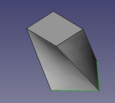
Two or more wires can be used to define the bounds of a solid and the loft tool will create a solid by sweeping the area between them. In the following screenshot, two rectangular shapes were positioned one above the other and rotated slightly. The loft tool creates a twisted cuboid by connecting the two:
Python is a high-level programming language that is easy to learn, easy to read, and powerful. To learn more about the Python programming language, go to www.python.org.
FreeCAD's use of Python as its scripting language makes it extremely flexible for modeling parts. With Python in control, a user can do things that would be hard to do manually.
With this recipe, a model of a servo motor is rendered.
For this recipe the Python console is needed. Make sure it's open. In the menu bar, click on View | Views and then make sure Python console is checked. The Python console will be located in the bottommost panel in FreeCAD. It looks similar to the following screenshot:
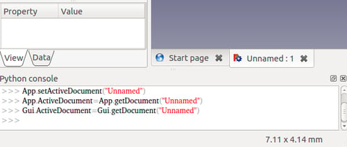
You will also need to have a document open in order for the Python scripted solid model to have a place to appear.
Enter the following text into the Python console:
import Part
from FreeCAD import Vector

plate = Part.makeBox(40,40,5,Vector(-20,-20,0))
hole1= Part.makeCylinder(1.5,5,Vector(-15,-15,0))
hole2= Part.makeCylinder(1.5,5,Vector(-15,15,0))
hole3= Part.makeCylinder(1.5,5,Vector(15,15,0))
hole4= Part.makeCylinder(1.5,5,Vector(15,-15,0))
faceplate = plate.cut(hole1)
faceplate = faceplate.cut(hole2)
faceplate = faceplate.cut(hole3)
faceplate = faceplate.cut(hole4)
motorbody=Part.makeCylinder(17.5,60,Vector(0,0,5))
shaft = Part.makeCylinder(3.175,15,Vector(0,0,-15))
servo = motorbody.fuse(faceplate)
servo = servo.fuse(shaft)
servo.translate(Vector(-20,-20,0))
servo.rotate(Vector(0,0,0),Vector(0,1,0),-90)
Part.show(servo)
Make sure to press the Enter key after the last line.
You should see a 3D solid in the graphics screen of FreeCAD that looks similar to the following graphic:

At the start of the script, FreeCAD needs some of its modules imported:
import Part
from FreeCAD import Vector
Without importing these, the script could not do anything beyond what is already in the standard Python library. The Part module gives access to geometric objects in FreeCAD. The Vector module is related to translating and rotating objects.
In lines like plate = Part.makeBox(40,40,5,Vector(-20,-20,0)) the Part module gives us a way of creating a solid box that is 40 mm x 40 mm x 5 mm big, which will be the face plate for our servo motor model. It is moved along a vector; 20 mm in the x direction; 20 mm in the y direction; and 0 mm in the z direction. FreeCAD allows us to create many types of solids in Python such as cylinders with Part.makeCylinder, spheres with Part.makeSphere, cones with Part.makeCone, and toruses with Part.makeTorus.
FreeCAD can cut
3D objects and fuse them to each other. In Python code that looks like this: faceplate = plate.cut(hole1), we are cutting the plate with hole1. Fusing objects together can be seen in a line like servo = motorbody.fuse(faceplate), where motor body is fused to faceplate.
At the end of the script, we make our servo motor visible by showing it using the following code:
Part.show(servo)
You can use the Python console in FreeCAD to help you explore the depths of the the Part module. Just start typing Part. into the console and FreeCAD's auto-completion feature will show you what classes are available and give you tips. The . is what causes the console to auto complete.
Here is what the auto completion feature looks like in action:
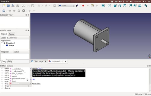
Notice how it gives you a helpful tip on the makeBox class.
Go to https://sourceforge.net/apps/mediawiki/free-cad/index.php?title=Topological_data_scripting for more info and examples of how to work with Python in FreeCAD. More examples can also be found by searching http://www.thingiverse.com/ with the keyword freecad.
The Python programming language in FreeCAD allows us to use PyQt4 or PySide to add our own widgets to make custom graphical user interfaces. In this recipe, we will create a dialog box that lets us create a simple box.
If the Draft workbench is functioning properly in FreeCAD, then you already have PyQt4 installed on your computer. Open a new document, so that we have space for our 3D box to appear.
The following is some code that will make a dialog pop-up, which lets us create a 3D solid box with a few parameters:
Type the following code into the Python console exactly as shown. Python is case and indent sensitive. Be consistent on indentation. We will use four spaces per indent here. An intent looks like a tab in this text. I have added
\(backslashes) to some lines that won't fit on the printed page in their complete form.from PyQt4 import QtGui,QtCore import Part,FreeCAD from FreeCAD import Base,Vector class BoxExample(QtGui.QWidget): def __init__(self): super(BoxExample, self).__init__() self.initUI() def initUI(self): self.setGeometry(100, 100,300, 200) self.setWindowTitle('Make a Box!') self.lengthLabel = QtGui.QLabel("Length: ",self) self.lengthLabel.move(50, 15) self.length = QtGui.QLineEdit(self) self.length.move(100, 15) self.widthLabel = QtGui.QLabel("Width: ",self) self.widthLabel.move(50, 50) self.width = QtGui.QLineEdit(self) self.width.move(100, 50) self.heightLabel = QtGui.QLabel("Height: ",self) self.heightLabel.move(50, 85) self.height = QtGui.QLineEdit(self) self.height.move(100, 85) self.centered=QtGui.QCheckBox("Center on XY",self) self.centered.move(80, 115) self.centerbox = False self.centered.stateChanged.connect(self.changeState) self.okButton = QtGui.QPushButton("Create Box",self) self.okButton.move(160, 150) self.show() QtCore.QObject.connect \ (self.okButton, QtCore.SIGNAL("pressed()"),self.box) def changeState(self, state): console=FreeCAD.Console if state == QtCore.Qt.Checked: console.PrintMessage("Box will be centered\n") self.centerbox = True else: self.centerbox = False def box(self): l = float(self.length.text()) w = float(self.width.text()) h = float(self.height.text()) if self.centerbox == True: box = Part.makeBox(l,w,h) box.translate(Base.Vector(-l/2,-w/2,0)) else: box = Part.makeBox(l,w,h) Part.show(box) d = BoxExample()When the dialog box pops up, fill in the values and click on the Create Box button. A simple 3D box should appear in the FreeCAD document. It looks similar to the following screenshot:

We start by creating a class that holds all of our dialog box functions:
class BoxExample(QtGui.QWidget):
The code within the BoxExample class that is part of the function def initUI(self): is used to set up
the widgets for our dialog. Lines that have QtGui.QLabel in them let us label the textboxes that are made with QtGui.QLineEdit(self). There is a checkbox and a button towards the end of the function in the form of QtGui.QCheckBox and QtGui.QPushButton respectively. def changeState(self, state): is used to see if our Center on XY checkbox is checked.
The following lines of code are used to connect the button labeled Create Box to the next function:
QtCore.QObject.connect \
(self.okButton, QtCore.SIGNAL("pressed()"),self.box)
I used the \ continuation character to fit one long line of code onto the formatted text of this book, so these two lines appear to be one to Python.
The def box(self) function
does the work to create the 3D solid box in the document. box = Part.makeBox(l,w,h) creates the box and Part.show(box) makes it appear in our document.
Within FreeCAD Python scripting, we don't use a main call, like we would have if we were making a standalone application. Instead we use d = BoxExample() to invoke and show our BoxExample() class. This is what turns our dialog box on.
To learn more about dialog creation for FreeCAD go to https://sourceforge.net/apps/mediawiki/free-cad/index.php?title=Dialog_creation.
One of the first places that a new Python programmer should check out is the official Python documentation website available at http://python.org/doc/.
There is also a good intro to PyQt programming available at http://zetcode.com/tutorials/pyqt4/firstprograms/.
To make programming dialogs a lot easier, you will want to use Qt Designer, a graphical dialog creation tool. It will let you create dialogs with a graphical editor that can be converted into Python code. If you are using Ubuntu Linux as your operating system, look in Synaptic for qtdesigner.
This following web page gives a good introduction to creating dialogs for FreeCAD:
https://sourceforge.net/apps/mediawiki/free-cad/index.php?title=Dialog_creation
Many of the tools in the Part Design workbench will seem familiar from the Draft workbench. The workflow however is quite different. Built around the idea of feature-based design, geometry in the Part Design sketcher is first drawn very roughly and then refined with constraints. As the constraints are added, the built-in solver will adjust the geometry to satisfy the constraint requirements.
In this recipe, we'll design a simple part that has features in two axes and show how it can be revised with constraints. In a later recipe, we'll add features to this part.
Begin with a new, empty document. Switch to the Part Design workbench and click on the button to create a new or edit the selected sketch. A dialog will popup asking which plane you want the sketch oriented on. Select the XZ-Plane option and click on OK.
Roughly draw the end profile of the part. Don't worry about accuracy at this point. The following example was drawn with an arc and a wire:

Add geometric constraints. Constraints are added by selecting the parts of the sketch to be constrained and pressing the appropriate constraint button. A new constraint icon will be added to the drawing and it will be listed in the left-side panel.
Start by adding horizontal and vertical constraints to any crooked lines.
If lines are supposed to connect, select the vertexes and add coincident constraints.
Select pairs of matching lines and add an equality constraint. This forces the lines to be equal length.
When the sketch looks symmetrical, add dimension constraints. Start by constraining the most important dimensions. For instance, we've constrained the radius of the arc to 25 mm.
As you add constraints, watch the solver message at the top of the task panel. As the number of Degrees Of Freedom (DOF) approaches zero you may find it difficult to add constraints without getting a conflicting constraints error. Grabbing a vertex or segment and dragging it can show you where the sketch is still under constrained.
If the sketch gets to 2 DOF and dragging a segment just moves the entire sketch, it's time to lock it. Pick a vertex (we used the center of the arc) and click on the lock button. This will add vertical and horizontal distance constraints which lock the vertex to the origin of the coordinate system. A fully constrained sketch will turn green. Celebrate.

Click on the close button in the task panel. Use the pad tool to pad the sketch to 75 mm and rotate the sketch to see your part.
Even after the sketch has been padded, you can still edit it by double-clicking it in the tree. When saved, your changes will be immediately incorporated into the part.
Constraints limit the ways in which an object can transform. A circle on a plane can be moved in two directions and can have its radius changed. Thus it has three degrees of freedom. When its radius is constrained it has 2 DOF and when its center is locked in X and Y, it is considered fully constrained.
Geometric constraints are those that affect the shape or relationship of entities; horizontal, vertical, tangent, symmetric, and so on.
Dimension constraints have a number. Double-click the constraint to edit the value. Length, radius, and angle are all dimension constraints.
Modeling with constraints is very practical for discrete parts where the features have an implied relationship between them.
Avoiding and eliminating conflicting constraints is the biggest challenge most users face with the sketcher. Practice goes a long way towards improving your skills but following some basic guidelines will also help.
Apply symmetry constraints first. Next apply geometric constraints (horizontal, vertical, tangent, and so on) before dimension constraints (anything with a number).
When possible, fix the horizontal or vertical distance rather than constraining the length.
Try to apply coordinate locks last. In other words, try to get the sketch constrained with itself before you try to constrain it to the coordinate system.
It's generally easier to use several simple sketches to build up the complexity of your part rather than one large sketch with many constraints. Keep your sketches as simple as possible. Whenever possible, use chamfer and fillet operations on the solid rather than modeling the beveled or rounded corners in the sketch.
It's rare that all the features of the part we want to design are in the same two-dimensional plane.
Imagine that we want to add holes to the top surface of the part we designed in the Modeling with constraints (Must know) recipe as shown in the following screenshot. To do this, we need a way to associate a new sketch with the top face of the part.
An external constraint gives us a way to relate elements of our sketch to entities that are not in the sketch itself, like the face of a part.
In this recipe we'll also show how features in a sketch can be related to an existing object.
Along the way, we'll also introduce construction lines and external constraints.
This recipe uses functionality from FreeCAD version 0.13 and later. Make sure you are using a recent release or development snapshot.
Open the model created in the Modeling with constraints (Must know) recipe. Set the view to top so you're looking down on the part from above.
Select the top face of the part so it is highlighted and click on the sketch button. The new sketch will be mapped to the face.
Draw four circles to represent our bolt holes. Select all four by clicking the edge (not the center) and set an equality constraint so they're the same size.
Select one of the four and add a radius constraint. Set the radius to 3.5 mm. Now all four can be resized by changing one number.
We want the holes to be positioned symmetrically. Select the centers of the top two holes and the vertical axis. Add a symmetry constraint. Repeat for the bottom two holes. The two sets of circles are now independently symmetrical.
Draw a line from the center of the top-right hole to the center of the bottom-right hole. Make sure the end points are coincident with the center of each circle. Select the line and make it into a construction line by clicking on the construction mode icon.

Set a length constraint on the construction line of 50 mm.
Now we need a way to set the position of the holes relative to the edge of the part.
Click on the External Constraint icon and select the right edge of the original solid. The edge and its vertexes can now be referenced in constraints as though they were a part of the sketch.

Select the center of the bottom-right circle and the bottom-end point of the external constraint line. Add a horizontal distance constraint (11 mm). Repeat and add a vertical distance constraint (15 mm).

The sketch should be fully constrained. To create holes all the way through the block, close the sketch and use the pocket tool. Set the pocket depth to at least 50 mm.
Sketches can be drawn on the planar faces of existing solids to add features such as protrusions or recesses.
Construction geometry can be added to any sketch. These lines, circles, and arcs don't become part of the final object but can take all the same constraints. They assist in drawing other entities and establishing relationships between entities.
An external constraint line is similar to a construction line but is an edge selected from the face on which a sketch is being drawn.
To use external constraints, a sketch must be mapped to a face. This happens automatically when you begin a sketch by selecting a face of an object. However, it is also possible to apply an existing sketch to a face on which it wasn't originally drawn.
Select a face and click the menu Part Design | Map Sketch to face.
In the dialog, select which sketch to map to the face and click on OK. Mapping a sketch to the face puts the sketch into edit mode. Adjust the sketch if necessary and close it. A sketch can be remapped to a different face but cannot be mapped to multiple faces at the same time.
In addition to using the Sketcher interactively and graphically we can use Python to program it automatically.
For this recipe, we need the Python console open. In the menu bar, open View, then Views, and then make sure that Python console is checked.
Enter the following code block into the console:
from Sketcher import *
import Part
import FreeCAD as App
from FreeCAD import Vector
if(App.activeDocument() == None):App.newDocument()

f = App.activeDocument().addObject("Sketcher::SketchObject",\"Sketch")
f.addGeometry(Part.Line(Vector(0,0,0),Vector(2,20,0)))
f.addGeometry(Part.Line(Vector(0,0,0),Vector(20,2,0)))
f.Constraints = [Constraint('Vertical',0),\Constraint('Horizontal',1)]
App.activeDocument().recompute()
Double-click on the Sketch icon in the Project tree.
Notice the horizontal and vertical constraint symbols (the small red bars). Also notice that the lines have end points but they aren't constrained.

Grab either of the lines and move it and the other one won't move with it.
Add some more Python code to the console to constrain some points:
StartPoint = 1 ;
l = f.Constraints
l.append(Constraint('Coincident',0,StartPoint,1,StartPoint))
f.Constraints = l
App.activeDocument().recompute()
Notice how one end of each line has connected to the other.
Try moving one of the lines around the screen and you will see that the lines move together.

Import all available functions in the Sketcher module:
from Sketcher import *
We will need the Part module to make geometric objects:
import Part
The FreeCAD module will let us manipulate the document:
import FreeCAD as App
We will need to give our line segments end points, so we need:
from FreeCAD import Vector
If a document isn't already open create a new one:
if(App.activeDocument() == None): App.newDocument()
Create a new Sketch object:
f = App.activeDocument().addObject("Sketcher::SketchObject",\"Sketch")Add geometry to the sketch:
f.addGeometry(Part.Line(Vector(0,0,0),Vector(2,20,0)))
f.addGeometry(Part.Line(Vector(0,0,0),Vector(20,2,0)))
Add some constraints to the sketch to make the lines horizontal and vertical:
f.Constraints = [Constraint('Vertical',0),\Constraint('Horizontal',1)]Recompute the sketch to see things after changes:
App.activeDocument().recompute()
Let's add a name for startpoints on our lines:
StartPoint = 1
Create a proxy object that is equal to our original, because we cannot add constraints directly to it:
l = f.Constraints
Append more constraints to our proxy object.
0is the first line and1is the second:l.append(Constraint('Coincident',0,StartPoint,1,StartPoint))Make the original constraints equal to the proxy and recompute:
f.Constraints = l
App.activeDocument().recompute()
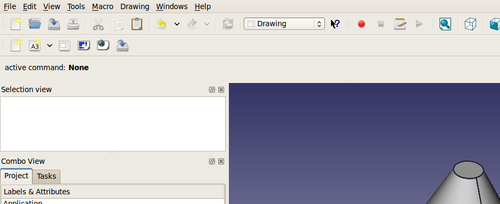
The Drawing workbench lets us create 2D views of 3D objects for presentation in formats that are ideal for printing. In this recipe, we will create a drawing with three views.
Select the Insert new drawing icon:

Pick the Insert an orthographic projection icon:

A new task will pop up in the Task panel. Select a Primary View:


Click on the OK button in the Task panel.
While the Page icon is selected in the Project tree, click on its Data tab.
Double-click on the button that has ... as its label.

A text dialog box will popup. Edit the values, putting in your name, the date, and so on:

Click on the recompute button to see the results:

FreeCAD uses algorithms from the OpenCascade CAD kernel to calculate 2D projections from 3D objects. FreeCAD takes advantage of this and inserts those projections onto a SVG canvas. This canvas is actually a template that was imported during step 1.
The Orthographic Projection dialog in the Task panel creates different projections at set angles, scales them, and spaces them in a consistent way.
The text dialog helps us edit SVG editable texts and fills in the text information in the bottom-right corner of the title block.
If you want to give your drawing to someone who doesn't have FreeCAD, you might want to export it as a PDF file.
Most CAD applications don't live in a vacuum and need to be able to save to different file formats for other CADCAM programs to use. FreeCAD is no exception. There are some tasks that FreeCAD doesn't do especially well, such as dimensioning drawings. Other applications, such as LibreCAD or DraftSight do better in this area. Exporting 2D geometry to DXF format is an excellent way of facilitating this.
The first rule of exporting geometry is to make sure your geometry is clean and consistent. This means that the end points of lines and arcs that are meant to be connected should be connected with no gaps. Line segments hiding under other line segments should be deleted. Arcs and lines that are impossibly small should also be deleted. Don't leave any extra entities that aren't necessary in your document for exporting. 3D geometry does not export as DXF format in FreeCAD.
In the Project tree, select 2D geometry from a Sketch or the Draft workbench. Be sure and select all geometry that you want exported.
From the top menu, select File and then Export.
In the lower-right corner of the Export file dialog, select Autodesk DXF.
In the Name entry box, give your file a name with the
*.dxfextension.Select the directory where you want your file saved.
Sometimes it is desirable to use geometry that was created in other CAD or modeling programs. FreeCAD can import a wide variety of file types. DXF, STEP, STL, SVG, VRML, Collada, and IDF are just some of the file formats that it can use.
In this recipe, we will open a DXF file and use the geometry in it to form a 3D solid.
You should have a DXF file produced by a CAD program such as QCAD, LibreCAD, Draftsight, or AutoCAD available to produce a DXF file.
In FreeCAD, open the Draft workbench and then select Preferences from the Edit menu.
In the Preferences dialog, click on the Draft icon and then click on the Import/Export tab.
Under DXF format options, change Import style to None (fastest).
Uncheck all the other boxes in that same section. Click on Apply and then OK.

Create some geometry in another CAD program. For this example, we will use DraftSight to create a simple shape. The following is a polyline rectangle with four fillets and a circle:
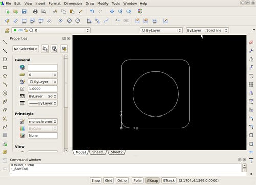
The lines and arcs in this drawing are a polyline. These will translate nicely into FreeCAD and help us create a solid to subtract the circle from.
In FreeCAD, select Import from the File menu.
Select the
dxffile that you want to import.In the Combo View, look at the Project tab and expand the icons.

Switch to the Draft workbench so that we can Upgrade the Circle with the icon that looks like an arrow pointing upward.
Select the geometry labeled as Polyline and use the Part workbench with the Extrude icon to extrude it into a solid.
Extrude the geometry labeled Circle into a solid. Make sure that its height is the same as the solid made from Polyline.
Select the solid that you created from Polyline and then the solid created by Circle.
Use the Boolean Cut operation in Part workbench to subtract the Circle solid from the Polyline solid.

DXF importing relies on code within the Draft workbench, so its settings are controlled from Draft preferences. The dxf polyline imported in as a face that could be extruded in the Part workbench. The Draft workbench has tools for changing other 2D geometry into faces, using the Upgrade tool, which allows the Part workbench to make solids from them. Faces will extrude as solids, whereas a closed shape without a face will just extrude into a thin object that looks like walls.


