


Exploring the OSI Model and TCP/IP
As you embark on the journey of acquiring new knowledge and developing your skills as an aspiring network professional, you will be exploring the latest networking technologies and concepts needed by professionals within the networking and Information Technology (IT) industry. The CompTIA Network+ certification is filled with the latest technologies and content for the next generation of network professionals. It ensures learners gain the knowledge and in-demand skills needed to support the network infrastructure that organizations rely upon each day.
As an aspiring network professional, I’m sure you are very eager to dive into the technologies and start looking at network traffic, and even learn about cyber-attacks and network security solutions to help defend organizations from threat actors. However, all great journeys of becoming an expert within a field of study, such as networking, begin with developing a solid foundation and gaining a strong understanding of the fundamentals of network communication.
During this chapter, you will learn about the importance of and the need for using a protocol suite on a network to communicate with devices and share resources. You’ll be exploring each layer of both the Open Systems Interconnection (OSI) and Transmission Control Protocol/Internet Protocol (TCP/IP) networking models, and how all the layers work together to ensure systems can exchange messages over a network. Additionally, you’ll gain fundamental knowledge of how datagrams are encapsulated and de-encapsulated when devices send and receive messages. Lastly, you’ll gain the hands-on skills of exploring the headers and fields found within packets using industry-recognized tools.
In this chapter, we will cover the following topics:
- The need for networking models
- Exploring the OSI model
- Understanding TCP/IP
- Data encapsulation concepts
- Analyzing network packets
Let’s dive in!
Technical requirements
To follow along with the exercises in this chapter, please ensure that you have met the following requirement:
- Wireshark: https://www.wireshark.org/
The need for networking models
One of the most frequently asked questions from many learners who are starting their journey in the field of networking is, what is a network? A network is defined as having two or more computing devices interconnected, using a set of communication protocols (rules) that allow them to share a resource between themselves. A resource can be anything, such as a file on a centralized server, a multiplayer game on an online server, and even a network-connected printer. Networks are all around us and we use them every day to communicate with each other, share information, and even deliver an online service. The largest network in the world is the internet and every day it is continuously growing as more devices are connecting to it and organizations are joining their networks to the internet.
Important note
In the 1960s, the age before the internet, the US Department of Defense (DoD) provided financial funding to the Defense Advanced Research Projects Agency (DARPA), which allowed computer scientists to start developing a prototype to allow academic institutions such as universities and government-funded research centers to establish a computer network over existing telephone lines. This early generation prototype was known as the Advanced Research Projects Agency Network (ARPANET). However, the ARPANET was unable to support communication as expected and crashed when a user attempted to send an input such as a string of text across the ARPANET. Therefore, the project was dismissed.
While the internet is the largest network in the world, it is not owned by a single person, organization, or government, but various organizations globally have the responsibility of ensuring its sustainability, availability, security, and scalability. The following are important organizations that play key roles on the internet:
- Internet Society (ISOC): The Internet Society is a non-profit organization whose mission is to encourage the open development, usage, and evolution of the internet in a way that is beneficial to everyone in the world. You can learn more about the Internet Society on their website at https://www.internetsociety.org.
- Internet Engineering Task Force (IETF): The IETF is an organization with the responsibility of both developing and promoting internet technical standards such as protocol suites. Simply put, the IETF is responsible for ensuring the internet is a better place for all. You can learn more about the IETF on their website at https://www.ietf.org.
- Internet Architecture Board (IAB): The IAB is a committee within the IETF that serves as an advisory board for overseeing the internet standards processes and the IETF architectural designs. You can learn more about the IAB on their website at https://www.iab.org.
- Internet Assigned Numbers Authority (IANA): IANA is responsible for coordinating, distributing, and managing domain names, number resources, and protocol assignments on the internet and networks. Additionally, IANA oversees the Autonomous System Number (ASN) allocation and Domain Name System (DNS) root zone management. You can learn more about IANA on their official website at https://www.iana.org.
- Internet Corporation for Assigned Names and Numbers (ICANN): ICANN is a non-profit organization that is responsible for the coordination, procedures, and maintenance of both namespaces and numerical spaces on the internet to ensure its stability and security. You can learn more about ICANN on their website at https://www.icann.org.
Imagine a world without computer networks; there would be so many challenges that both organizations and individuals would face each day. Imagine an employee of a company who wants to send a document to an employee of another organization. The traditional method would be to securely package the document with its contents within an envelope and use a courier service for delivery. However, using the internet and email services, the sender can attach the document file within an email message and forward it to the intended destination (recipient); the time it takes the message to be delivered between the sender and the recipient via the internet is highly reduced with the help of networking protocols compared to using traditional courier services.
Within the educational industry, there are many amazing certifications, qualifications, and study programs from various academic institutions around the world. Using the internet, educational institutions can deliver their learning content to students around the globe compared to the traditional on-campus learning method. Companies are also using networking technologies and the internet to extend their products and services beyond traditional borders. To ensure communication between networked devices such as computers works as expected, it’s vital to understand the need for vendor-neutral networking models for intercommunication.
In today’s world, many types of devices connect to our networks compared to traditional computers and servers. Some of these new devices include smart technologies and Internet of Things (IoT) devices such as smartphones and tablets, gaming consoles, and smart electronics and appliances. Connecting computers and IoT devices to a network is a seamless process and everything works as expected. However, back in the 1970s, early computer vendors started developing their proprietary networking models to allow their computers to intercommunicate and share resources over a network. For many organizations, this concept may have worked well if the company had bought computers from a specific computer vendor only. If, in the future, the company decided to purchase computers from another computer vendor, the company would not be able to create a unified network with all the computers from different vendors. This was one of the biggest issues with communication in the early days as each computer vendor developed its own proprietary networking model. As a result, companies would need to create separate networks for each vendor’s device; this concept does not support network scalability for a growing company. This intercommunication issue led to the development of a common networking model that allows different devices to communicate over a network.
In the 1970s, the International Organization for Standardization (ISO) took the initiative on developing the OSI networking model for computer networks. The OSI model was designed to be a common standard for using networking protocols (rules) to allow intercommunication between devices that are connected over a network. However, the OSI model didn’t have the traction needed to be implemented as a networking protocol suite within systems. At the same time during the 1970s, the US DoD also started working on developing a vendor-neutral protocol suite for intercommunication across computer networks; this protocol suite included the research and efforts of many organizations, such as universities and government agencies, to develop the networking protocols that made up the protocol suite we all know today as TCP/IP.
Important note
A network protocol is simply the rules and guidelines that are used by a device to allow communication or the exchange of messages from one device to another. There are many network protocols, each of which has a different purpose and characteristic. During this book, you will discover and learn about their functionalities and use cases.
In the 1980s and 1990s, organizations began implementing computer systems that supported various networking models such as those that were proprietary to specific computer vendors and even TCP/IP within their companies. As mentioned previously, companies experienced the challenge of interconnecting computers that used different networking models from computer vendors. Eventually, by the early 2000s, vendors had started to fully adopt and implement TCP/IP as the preferred network protocol suite to allow intercommunication between devices from different vendors. Hence, TCP/IP is considered to be the universal language of communication within the networking industry.
Important note
AppleTalk was a short-lived proprietary networking model created by Apple in 1985 and was used on Apple devices until 1995, when the TCP/IP protocol suite was adopted. Another short-lived networking model was Novell NetWare, a proprietary model created by Novell back in 1983 using the Internetwork Packet Exchange (IPX) networking protocol until 1995, when TCP/IP was adopted.
Having completed this section, you have gained an understanding of the importance of using a networking model to ensure devices can successfully communicate with one another over a network. In the next section, we will explore the roles and responsibilities of each layer of the OSI model.
Exploring the OSI model
The OSI model was originally developed to be an open networking model for computer networks to allow different devices to use a set of mutual protocols (rules) to allow communication between each other over a network. While the OSI model is commonly described as a reference model because it’s not technically implemented on any networked devices such as computers, servers, or networking devices, networking professionals still use its terminology during their discussions and when writing documentation and publications. Therefore, as aspiring networking professionals within the industry, it’s vital to gain a solid understanding of the characteristics and functionality of each layer within the OSI model.
The OSI model contains a total of seven layers that describe how communication occurs between one device and another over a network. Each layer of the OSI model has a unique role and responsibility to ensure a message from a sender contains all the necessary details to be successfully delivered to the intended destination. Imagine the challenges that would exist if networking models did not exist. Imagine writing a letter to a friend and posting it via the postal service with the hope it will be successfully delivered to the destination. However, if the address information is incorrect on the envelope, the postal service may have difficulties locating the destination. If the contents of the message are not correctly formatted or structured, the recipient of the message will not be able to clearly understand the contents. Similarly, on a network without a networking model or protocols, computers will have challenges ensuring their messages are delivered to their destination and that the contents of the messages are properly formatted and structured. Hence, the OSI model is a seven-layered networking model that contains the protocols (rules) and guidelines on how systems can communicate over a network.
The following diagram shows the seven layers of the OSI model:

Figure 1.1 – OSI model
As shown in the preceding diagram, the seven layers of the OSI model are in the following order:
- Application
- Presentation
- Session
- Transport
- Network
- Data Link
- Physical
At each layer of the OSI model, when a message exists at a specific layer, the message is commonly referred to as a Protocol Data Unit (PDU). A PDU is simply described as a single unit of data/information that can be transmitted from one host to another over a network. As the PDU is created at the Application layer of the OSI model of the host, it is referred to as data, which is the raw message. As the PDU travels down the OSI model, each of the lower layers is responsible for attaching additional information within a header onto the PDU to ensure proper addressing details are inserted to deliver the message. This process is commonly referred to as encapsulation. When a host on the network receives the message, the PDU travels upward on the OSI model, where each layer de-encapsulates the message, removing the header information until the raw message is delivered to the Application layer on the recipient device.
The following diagram shows an overview of the process of sending and receiving a message between two devices using the OSI model:

Figure 1.2 – Sending and receiving messages
As shown in the preceding diagram, when the computer sends a message, the message is created at the Application layer of the OSI model and works its way down the stack to the Physical layer. When the server receives the message through the network, the message is sent across the Physical layer and enters the Data Link layer before moving upward to the Application layer of the server.
Furthermore, the upper layers of the OSI model, such as the Application, Presentation, and Session layers, are designed to provide support for the application’s functionality; in other words, they are designed to ensure the datagram (raw message) that’s created by the sender can be transmitted across the network between the sender and receiver. The lower layers of the OSI model, such as the Transport, Network, Data Link, and Physical layers, focus on inserting the addressing information needed to deliver the datagram to the destination. Simply put, you can think of the lower layers as having the responsibility of ensuring end-to-end connectivity between hosts over a network.
Over the next few subsections, you will gain an in-depth understanding of the roles and responsibilities of each layer of the OSI model and how they help devices, such as computers, exchange messages between themselves and another host.
Application layer
The Application layer is the layer that is the closest to the end user, such as yourself. This layer provides an interface so that you can run the applications of a host such as a computer or even a smartphone to communicate with the underlying network protocols of the OSI model. To gain a better understanding of the responsibility and importance of the Application layer, imagine you’re interested in visiting the CompTIA website to learn more about the examination details of the CompTIA Network+ N10-008 certification. A typical user will simply open their favorite web browser application and use their preferred search engine to find CompTIA’s official website at www.comptia.org. Once the user clicks on the Uniform Resource Locator (URL) address, within a couple of seconds, the website downloads onto your device and the web browser renders the web language into something understandable to humans.
The following screenshot shows a standard web browser using HTTPS as the Application layer protocol to communicate with the CompTIA web server:

Figure 1.3 – Observing an Application layer protocol
While this process seems very simple and works well, there are a lot of underlying network protocols that work together to ensure your computer can access the internet and view the website. The end device, such as your computer or even smartphone, has an operating system that allows you to interact with the hardware components of your device to perform tasks. As a user, we generally install additional applications onto our operating system to add new functionality compared to the core functions and features that are present on the bare version of the operating system. Installing a web browser on your computer allows your operating system to interact with the Hypertext Transfer Protocol (HTTP) and Hypertext Transfer Protocol Secure (HTTPS) protocols. These are two examples of Application Layer protocols that allow you to interact/interface with web services on a network. Another example is using an email application such as Microsoft Outlook or Thunderbird running on your local computer to interact/interface with the Simple Mail Transfer Protocol (SMTP), an application layer protocol that is responsible for sending email messages over a network.
Each application layer protocol creates a datagram (raw message) or PDU that can only be interpreted by the same application layer protocol that created it. Simply put, a PDU created by HTTPS can only be interpreted by HTTPS and not another application protocol such as SMTP. As you may recall, a protocol is a rule that allows communication between devices over a network. Therefore, each protocol uses its own set of rules and structure for creating a PDU. At the Application layer, the PDU contains only the raw data created by the application layer protocol and does not have any addressing information needed to be delivered to the intended recipient. At the Application layer, the PDU is known as Data. Once the application layer protocol finishes its task of creating the PDU, it passes it down to the next layer, which is the Presentation layer.
Presentation layer
While the application layer protocols of the Application layer create system-dependent data (for example, ASCII or JPEG), the Presentation layer transforms it into an independent format. The PDU is then sent to lower layers to address the receiving system. This allows the Presentation layer on the receiving system to transform the data back into the system-dependent format (ASCII or JPEG) that the Application layer requires.
To gain a better understanding of the Presentation layer, imagine writing a letter to your friend. If you don’t use the proper format of putting the destination delivery address and your sender’s address on the external envelope, the postal service may experience some challenges when attempting to deliver the letter to the correct postal address. Overall, the Presentation layer ensures the PDU is formatted in a way that it will be supported by the lower layers of the OSI model and work on the actual network. Hence, it’s important to ensure the PDU from the Application layer is formatted properly. At this layer of the OSI model, the PDU is still known as Data.
The following are the main responsibilities of the Presentation layer:
- Data formatting (encoding)
- Data compression
- Data encryption
- Data decryption
Once the Presentation layer finishes its task of formatting, encoding, and/or encrypting the PDU, it is sent down the OSI model stack to the next layer, known as the Session layer.
Session layer
Before a host can send a message to another host over a network, the sender needs to establish a logical session between itself and the destination device. The Session layer is responsible for ensuring that the devices across a network can create or establish a session between the sender and receiver. The Session layer is also responsible for maintaining the logical session (connection) between the hosts over the network. This allows each device to transmit their messages between themselves for the duration of the session. Lastly, the Session layer is responsible for terminating the logical session (connection) when both the sender and receiver are no longer communicating with each other. If the session is terminated during data transmission between the two hosts over the network, all data transmission will cease (stop) as well.
The following are the core functions of the Session layer:
- Create/establish a session
- Maintain the session
- Terminate a session
While the PDU exists within the Session layer, it is commonly referred to as Data. Once the Session layer completes its task, the PDU is sent down to the next layer within the networking model, known as the Transport Layer.
Transport layer
Networked devices such as computers, servers, and smart devices send and receive messages between each other very frequently and everything works well. Imagine if a client device such as a computer is requesting the web page from a web server on the internet. What occurs within the OSI model? At the Application layer of the client device, the HTTP application layer protocol of the OSI model creates an HTTP GET message to request the web page from the web server. Keep in mind that the Application layer is not responsible or concerned about how the data is delivered over the network. The data from the application layer protocol such as HTTP is sent down to the Transport layer.
Important note
In the TCP/IP protocol suite, the Transport layer is responsible for delivering the message between the Application layer and the network.
The Transport layer assigns a service port number to the PDU so that the receiving system will know how the Presentation layer should interpret and format the data. Then, the receiving system can read the data in the Application layer.
The following diagram shows a high-level visual representation of the client using HTTP to communicate with the same application layer protocol on the web server:

Figure 1.4 – Application layer protocol communication
The Transport layer ensures datagrams are delivered to the correct application layer protocol by assigning service port numbers to the PDU. Within an operating system that supports TCP/IP, there are 65,535 service port numbers.
The following diagram shows how these ports are categorized:

Figure 1.5 – Service port ranges
The service ports that exist within the range of well-known ports belong to the application layer protocols, which are very common on a network. Some of these common application layer protocols are HTTP, HTTPS, and SMTP. The registered port range belongs to users and organizations who have officially registered a service port number to operate on a custom build application or software. The private/dynamic range belongs to service ports that are temporarily used during communication, such as using a randomly generated service port on the sender’s device as the source port.
While many people will think these ports are physical ports or interfaces on a device, these service ports are logical ports within an operating system. The service ports are the logical entry, while the exit ports on a system are used as doorways for sending and receiving datagrams on a network. You can think of a service port as a traditional airport that is used as a port of entry and exit of a country via air travel. Each service port number is logically mapped to an application layer protocol, so the Transport layer assigns the source and destination service port numbers to the PDU when it’s received from the Application layer.
The following is a brief list of common application layer protocols and their corresponding service ports numbers:

Figure 1.6 – Common application layer protocols
Using the same analogy from earlier, the Application layer on the client device sends the datagram to the Transport layer; the Transport layer encapsulates (inserts) a layer 4 header onto the datagram that contains both the source and destination service port numbers. Once the layer 4 header is added to the datagram from the Application layer, the PDU is referred to as a segment.
The following diagram shows a segment at the Transport layer containing a source and destination service port number with the data received from the application layer protocol:

Figure 1.7 – Segment
As shown in the preceding diagram, the layer 4 header contains the source and destination service port numbers. The Data field contains the data received from the upper layer, such as the Application layer. The source service port number is a randomly generated number between 49,152 and 65,535. Since the source service port number is randomly generated by the operating system of the sender device, it is also referred to as an ephemeral port number. The source port number is important on the datagram as it informs the recipient about the sender’s return address, similar to putting the return address information on a traditional letter. The destination service port number is inserted into the datagram, which informs the destination device about which application layer protocol to deliver the message to. For example, if the client is sending an HTTP message from itself to a web server on the internet, the Transport layer of the client device will insert a randomly generated source port number such as 49,161 and set the destination service port as 80. It uses port 80 since the application layer protocol on the destination device (web server) is running a web service that uses HTTP and HTTP uses service port 80 by default.
The following diagram shows a visual representation of the client sending a message to the web server that is running HTTP as the application layer protocol on service port 80:

Figure 1.8 – HTTP Request message
The following diagram shows the addressing information used by the web server to respond to the client on the network:

Figure 1.9 – HTTP Response message
As shown in the preceding diagram, the Transport layer ensures the correct source and destination services ports are assigned to the HTTP Request and HTTP Response messages. As you have learned thus far, the Transport layer is all about transporting/delivering the messages from one device to another while ensuring the datagrams are delivered to the appropriate application layer protocol on the destination device.
Thus far, we have focused a lot on understanding how service port numbers play a vital role in communication over a network. However, the Transport layer contains two protocols that assist with transporting and delivering datagrams over the network. These Transport layer protocols are as follows:
- Transmission Control Protocol (TCP)
- User Datagram Protocol (UDP)
As mentioned earlier, the application layer protocols are not responsible for or concerned about the delivery of messages from a sender to a receiver over the network. Hence, the Transport layer uses either TCP or UDP to ensure the messages from the Application layer of the OSI model are delivered to the destination host. The service ports on a system can use either TCP or UDP for communication over a network. Over the next couple of subsections, you will learn about the similarities and differences between TCP and UDP.
Transmission Control Protocol
The Transmission Control Protocol (TCP) is a connection-oriented protocol that establishes a logical connection between the source and destination devices before exchanging messages over a network. This connection is commonly referred to as the TCP three-way handshake.
The following diagram shows a high-level overview of the TCP three-way handshake between two devices:

Figure 1.10 – TCP three-way handshake
The following is a breakdown of this process:
- The client device wants to communicate with the server, so the client device sends a synchronization (SYN) message to the server. The SYN message is used to initiate a connection with the server. Within the SYN message, a randomly generated sequence number is created. This is used to indicate the beginning or starting sequence number for the data that will be transmitted from the client, as shown in the following diagram:

Figure 1.11 – SYN sequence number
- The server receives the SYN message from the client and the server responds with an acknowledgment (ACK) message. Within the ACK message is an ACK sequence number; this number is the client’s sequence number + 1. The server also includes a SYN message within its response, containing a randomly generated sequence number to inform the client it also wants to initiate a connection; this message is known as a SYN/ACK, as shown in the following diagram:

Figure 1.12 – SYN/ACK sequence number
- The client receives the SYN/ACK message from the server and responds with an ACK message. The ACK message from the client contains an increment value of the SYN message received from the server, as shown in the following diagram:

Figure 1.13 – ACK sequence number
Keep in mind that a device will respond with an ACK message for each SYN message it receives over a network. The following diagram shows a more technical representation of the TCP three-way handshake as it occurs between two devices over a network, including randomly generated sequence numbers:

Figure 1.14 – TCP three-way handshake with sequence numbers
Using a network protocol analyzer tool such as Wireshark, network professionals can perform packet analysis on their network infrastructure and analyze the network traffic. The following screenshot shows the TCP three-way handshake captured using Wireshark on a real network:

Figure 1.15 – Wireshark capture
As shown in the preceding screenshot, packet #1 shows a sender, 192.168.0.2, sending a TCP SYN message that has a SYN sequence number of 0 to a destination device with an IP address of 192.168.0.1. Next, packet #2 indicates the device with the IP address of 192.168.0.1 responds with a SYN/ACK message that contains a SYN sequence number of 0 and an ACK sequence number of 1. Lastly, packet #3 indicates that the device with an IP address of 192.168.0.2 responds with an ACK message that contains an ACK sequence number of 1.
Important note
The sequence numbers used by TCP allow a destination device to easily reassemble incoming messages if they are received out-of-order compared to the order they were sent onto the network.
Once a TCP three-way handshake has been established, both hosts will begin sending messages to each other. When a client sends a message to another device using TCP as the Transport layer, the receiver of the message responds with an ACK packet to the sender. The ACK packet confirms the message was delivered successfully. If the sender does not receive an ACK packet from the intended destination host, after a while, the sender will attempt to retransmit the same message, repeating the process to ensure the message is delivered successfully. This is another benefit of using TCP when communicating over a network as it provides guaranteed delivery of messages and retransmits messages when needed.
When both hosts are no longer transmitting data between themselves over the network, TCP will attempt to gracefully tear down/terminate the connection using a four-step process, as shown here:

Figure 1.16 – TCP terminating a connection
As we can see, the client sends a FINISH (FIN) message to the server, indicating it no longer wants to maintain the session. The server responds with an ACK message to the client, indicating it is acknowledging that the client wants to terminate the connection. The server also sends a FIN message to the client to indicate it no longer wants to send any data. The final message is sent from the client – an ACK message – to confirm the termination.
The following are the benefits of using TCP as a transport layer protocol:
- Establishes a session such as the TCP three-way handshake before exchanging data.
- Provides reliability in delivering data over a network.
- Delivers data using the same order of delivery from the sender to the receiver.
- Uses flow control by creating a window size that has been mutually agreed upon between the source and destination hosts. The flow control window size determines the amount of data that can be sent at a time between the hosts.
While there are many benefits to using TCP as the preferred transport layer protocol, there are many disadvantages, such as the following:
- There is more overhead on a network when using TCP as the Transport layer protocol. For each message delivered to a destination device, the receiver responds with an ACK message.
- When a host is sending multiple messages to another host over a network, the messages are not sent all at once. TCP creates a logical window size between the source device and destination device that determines how much data can be sent at a time. TCP will send several messages within the TCP window and wait for acknowledgment messages from the receiver before sending more data. This creates a delay in the delivery of the messages.
In the next section, we will learn about the characteristics of another Transport layer protocol, the User Datagram Protocol (UDP).
User Datagram Protocol
UDP is another Transport layer protocol that assists with delivering messages between devices over a network. Unlike TCP, UDP is a connectionless protocol that does not establish a logical connection between the source and destination devices. Being a connectionless protocol, UDP does not provide any guarantee of delivery of messages over a network, so if any messages are corrupted or discarded, UDP does not attempt to retransmit those messages. UDP does not provide any acknowledgments when messages are delivered, so the sender does not know whether the messages were delivered to the destination host or not. This makes UDP an unreliable Transport layer protocol within the networking model.
When using UDP as the preferred Transport layer protocol, the sender device does not use sequence numbers. As quickly as the datagrams from the Application layers are being sent down to the Transport layer, the Transport layer uses UDP and quickly places the datagrams on the actual network without adding any sequencing information. Therefore, when a destination host receives incoming messages over the network, there is no way to determine how to properly reassemble the messages in their correct order.
While TCP may seem to always be the preferred Transport layer protocol, UDP has some advantages, such as the following:
- Since UDP does not wait for any acknowledgment from the destination host, clients can send messages faster across the network to the destination devices. It is beneficial for application layer protocols that are time-sensitive such as Voice over IP (VoIP) and Video over IP solutions that are used in real time.
- Low overhead on the network since no acknowledgment messages are returning to the sender.
- UDP is commonly used with application layer protocols, which are not dependent on delivery or require acknowledgment.
- UDP is commonly used when applications have more efficient means of guaranteeing delivery of data and do not want the additional overhead TCP requires.
Once the Transport layer inserts its layer 4 header onto the datagram using TCP or UDP, it sends the segment down to the next layer on the OSI model. In the next section, we will learn about the role and functionality of the Network layer within the OSI model.
Network layer
The Network layer of the OSI model is responsible for ensuring the logical addressing information is inserted into the datagram. On a network, each device requires a unique Internet Protocol version 4 (IPv4) or Internet Protocol version 6 (IPv6) address that allows them to communicate with devices on their local and remote networks. The Network layer encapsulates a layer 3 header onto the datagram by inserting the source and destination IP addresses of the sender and destination host. Without inserting the source IP address onto the datagram, the recipient of the message will not be able to return any messages. Without including a destination IP address in the message, networking devices such as routers will not know how to forward the message to its intended destination. Once the PDU from the Transport layer is encapsulated with the layer 3 header, it is referred to as a Packet.
The following diagram shows a high-level overview of a client sending a message to a server:

Figure 1.17 – Packet header
As shown in the preceding diagram, the packet contains a source IP address of 192.168.1.10, which belongs to the client device, and a destination IP address of 192.168.1.100, which belongs to the web server.
Additionally, the Network layer is responsible for the routing services that occur on the network. Devices such as routers are considered to be layer 3 devices that can interconnect different networks and forward packets between networking using the information within the layer 3 header of the packet, such as the destination IP address. Between a sender and receiver, there may be multiple routers and paths, and each time a router on the network receives a packet, it checks the destination IP address within the layer 3 header of the packet and the routing table on the router to determine whether a valid route to the destination exists. Therefore, a sender must insert the accurate layer 3 addressing (IP addresses) onto the layer 3 header of the packet to ensure networking devices such as routers can forward the packet to the intended destination.
Important note
The source IPv4 address on a packet may change due to the Network Address Translation (NAT) operating on a router. We will discuss the processes and needs of using NAT later in this book.
Internet Protocol (IP) is a connectionless layer 3 protocol that does not establish any logical connection or session between the sender and receiver of the message. Being connectionless simply means the IP will not create a dedicated, logical end-to-end session/connection before sending any data between the source and destination hosts over a network. Therefore, if packets are lost or corrupted during the transmission process, the messages are not retransmitted. Additionally, being connectionless does not notify the intended recipient about any incoming data/messages from a sender.
As the IP is a connectionless layer 3 protocol, it uses its best effort when transmitting data between sender and receiver devices over a network. Since it does not establish any end-to-end connections, it is unreliable and does not provide any guarantee that the data will be delivered to the destination host. However, it provides low overhead on the network as a connectionless protocol. Lastly, the IP indicates to the Transport layer whether or not to use the TCP, UDP, or other protocols in its header information. For example, if the data requires connection-oriented delivery, the IP will indicate TCP.
Important note
The operation of the IP is independent of the type of medium being used to transmit the data, such as wired, wireless, or even fiber optics. The lower layers, such as the Data Link layer of the OSI model, are responsible for ensuring the packets are prepared for the type of medium before they’re placed on the actual network. The Maximum Transmission Unit (MTU) describes the maximum size of a message that can be supported by network media. The default MTU size is 1,500 bytes.
Once the Network layer encapsulates the datagram with a layer 3 header, it passes it down to the next layer of the OSI model, known as the Data Link layer.
Data Link layer
The Data Link layer of the OSI model is responsible for moving the datagrams from the upper layers onto the actual network. This layer handles the flow control regarding how much data is placed (outgoing) on the media, such as a wired, wireless, or fiber optics network medium. It also manages the flow control of incoming messages from the physical network that is going to the upper layers of the OSI model on a host device.
The Data Link layer ensures datagrams from the upper lowers of the OSI model can access the network media. This is because the upper layers are not concerned about the media type that is used to transport the data over the actual network. Whether the Network layer creates an IPv4 or IPv6 packet, the Data Link layer encapsulates a layer 2 header and trailer onto the packet, creating a frame. This frame is crafted by the Data Link layer to meet the requirements needed for it to be sent over the physical network media. Furthermore, the Data Link layer handles error detection to identify whether any incoming frames from the physical network are corrupted and discard them.
Within the Data Link layer, two sublayers assist with ensuring frames are encapsulated, de-encapsulated, and placed on the network:
- Logical Link Control (LLC)
- Media Access Control (MAC)
Over the next few subsections, you will learn about the functionality and roles of each of these sublayers within the Data Link layer of the OSI model.
Logical Link Control
Logical Link Control (LLC) is a sublayer within the Data Link layer of the OSI model and is responsible for ensuring there is communication between the networking applications, software, and protocols of the upper layers of the OSI model and the local host’s device hardware such as the Network Interface Card (NIC). The NIC is a physical hardware-based component that allows a device such as a computer or a smartphone to interact with a wired or wireless network. The LLC inserts information within the frame, which indicates the network layer protocol that is being used within the frame. Additionally, the LLC allows many layer 3 protocols such as IPv4 and IPv6 to use the same network media and device.
Media Access Control
The Media Access Control (MAC) sublayer of the Data Link layer is responsible for performing the data encapsulation process and controlling access to the network device such as the NIC and network media (wired, wireless, or fiber optic). The MAC sublayer is also responsible for inserting the layer 2 physical addressing information onto the layer 2 header of the frame before placing it on the actual network media. The physical layer 2 address information is used to transmit and deliver frames being exchanged on a shared network medium. This layer 2 physical address is commonly referred to as a MAC address or a Burned-In Address (BIA).
A MAC address is a 48-bit address that is embedded onto a NIC by the vendor of the device. The MAC address on a NIC is considered to be unchangeable as the vendor of the device hardcodes it into the firmware of the component, hence the name burned-in address. However, within the cybersecurity industry, the MAC address of a device can easily be changed by a threat actor or cybersecurity professional based on the use case.
The 48-bit (6-byte) binary MAC address is usually written in hexadecimal (ranges 0 – 9, A – F) to easily identify an address apart from another. The first 24 bits (3 bytes) of a MAC address is known as the Organizationally Unique Identifier (OUI) as it is assigned by the vendor of the device/NIC. The OUI portion of a MAC address can help both network and cybersecurity professionals determine the type/vendor of a device that is connected to a network. The last 24 bits (3 bytes) of the MAC address are uniquely addressed.
The following diagram shows an example of the OUI portion of a MAC address:

Figure 1.18 – The OUI portion of a MAC address
MAC addresses are usually presented a bit differently based on the vendor of the device or operating system. The following are examples of the same MAC address in different formats:
0060.5c3d.d901: This format is usually used by Cisco systems00-60-5c-3d-d9-01: This format is commonly used on Microsoft Windows operating systems00:60:5c:3d:d9:01: This format is found on Linux-based systems
Important note
MAC addresses are not case-sensitive. However, you may notice they are commonly presented in a lowercase format, while some devices may display them in uppercase.
As an aspiring network professional, you can perform a MAC address vendor lookup by using any of the following websites and pasting the MAC address into the necessary field:
The following screenshot shows an example of the OUI lookup while using the Wireshark OUI Lookup Tool:

Figure 1.19 – OUI Lookup Tool
As shown in the preceding screenshot, the 00:60:5c code of the MAC address identifies the manufacturer of the device as Cisco Systems, Inc. This indicates that the device is most likely a networking device on the organization’s network.
Furthermore, the MAC sublayer handles error detection by inserting a trailer into the frame. The trailer of the frame contains the Frame Check Sequence (FCS), which includes the Cyclic Redundancy Check (CRC) value. The CRC is a one-way cryptographic, mathematical representation of the frame and its contents, which is calculated by using a process known as hashing. This helps systems validate the integrity of a message.
The following diagram shows a high-level overview of the layer 2 header and trailer of a frame:

Figure 1.20 – Frame
As shown in the preceding diagram, the frame is encapsulated with a layer 2 header that contains the source and destination MAC addresses, as well as the preamble, which is used to identify the start of the frame with sequencing and synchronization. The preamble helps the receiver of the message determine where the frame begins and how to reassemble the message in the correct order. This is because the messages may not be received in the same order they was sent on the network. Additionally, the trailer of the frame contains the FCS, which contains the CRC value for error detection.
The minimum support frame size on a network is 64 bytes, while the maximum support size is 1,518 bytes of all the contents, including the addressing headers, trailer, and data, excluding the preamble. Therefore, the data within a frame needs to be broken down into smaller blocks to support the acceptable frame sizes. In each of these blocks, data is assigned to the header and trailer to ensure they are delivered to the destination host over the network. The preamble of each of these blocks contains the sequencing details to help reassemble each block on the receiver device. These smaller blocks are commonly referred to as bits as they are placed on the network media in the Physical layer of the OSI model.
Physical layer
When the Data Link layer places the small blocks of data (bits) onto the physical network media, they are converted into electrical signals that are sent through media such as fiber optic, cable, or the air. At the Physical layer, many organizations define various standards and frameworks that describe how data can travel over the network media types. The Physical layer is simply the electrical wires, media type, and even the connections such as ports and interfaces on a network. Each physical component on a network needs a set of rules on how to send and receive data over the physical network.
The following is a list of important organizations that govern how data can be sent over the physical network, how data can be encoded, and the signaling methods:
- International Organization for Standardization (ISO)
- Telecommunications Industry Association/Electronic Industries Association (TIA/EIA)
- International Telecommunication Union (ITU)
- American National Standards Institute (ANSI)
- Institute of Electrical and Electronics Engineers (IEEE)
- Federal Communication Commission (FCC)
- European Telecommunications Standards Institute (ETSI)
The Physical layer of the OSI model addresses the following elements to ensure data can be sent over a network:
- Physical components
- Encoding
- Signaling
The physical components are the hardware elements that you see on a network, such as the networking devices, the physical interfaces/ports on a device, the networking cables that are used to interconnect devices, and so on. Each hardware device, whether it’s the NIC on a computer or a switch, uses a set of standards to ensure devices can transmit messages over the network.
The encoding process is handled by the Data Link layer before the bits are placed onto the Physical layer on the network. The encoding process describes the processes or methods used by a device to convert a stream of messages, such as bits, into code. This code is used to represent patterns that are recognizable by both the sender and receiver devices over the network. Think of an encoding process such as creating a mutual language that can be understood by two users or devices.
The signaling element of the Physical layer describes how the signals are created and placed on the physical network media by a sender device. The signals that are generated by the sender are electrical, wireless, or even optical (light), depending on the network media that is connected to a device. For example, a laptop connected to a wireless router will be converting the messages into a wireless signal before they are sent to the wireless router. A network device such as a switch may convert the messages into an electrical signal to place on a copper cable or into an optical signal (light) to place onto a fiber optic cable for transmission. These signals are usually represented using a 1 or 0 in the digital world; 1 may represent a high voltage on the wire while 0 may represent a low voltage on the wire.
With that, you have understood the fundamentals of the OSI model and how each layer plays a vital role in ensuring messages can be transmitted between a sender and receiver over a network. In the next section, we will learn about the TCP/IP protocol suite and how it compares to the OSI model.
Understanding TCP/IP
As mentioned previously, the US DoD developed a neutral networking model known as TCP/IP. This has been adopted by many computer and networking vendors. At the time of writing, TCP/IP is the dominating networking protocol suite and ensures devices can send and receive data over networks. Whether it’s a private network within your home, office, or the internet, TCP/IP is implemented within all devices connected to a network.
While TCP/IP seems to specify only two networking protocols – TCP from the Transport layer and IP from the Network layer of the OSI model – they are the most commonly used on networks. The TCP/IP protocol suite is a group of networking protocols that all work together to ensure messages can be exchanged over any type of network between sender and receiver devices.
The original version of the TCP/IP protocol is made is up of four layers compared to the seven-layered OSI model. Modern versions of the TCP/IP protocol suite have five layers, splitting the bottom layer into Physical and Data Link layers.
The following diagram shows a comparison of the original TCP/IP protocol suite and the OSI model:

Figure 1.21 – TCP/IP protocol suite
As shown in the preceding diagram, the following are the four layers of the TCP/IP protocol suite:
- Application
- Transport
- Internet
- Network Access
The Application layer of TCP/IP absorbs all the functionality and responsibilities of the Application, Presentation, and Sessions layers of the OSI model. The Transport layer of both the OSI model and TCP/IP has the same functionalities and responsibilities. The Internet layer of TCP/IP is equivalent to the Network layer of the OSI model. Lastly, the Network Access layer of TCP/IP is equivalent to both the Data Link and Physical layers of the OSI model.
Important note
The Network Access layer of TCP/IP is sometimes referred to as the Link layer or the Network Interface layer.
The following diagram provides a high-level overview of a computer sending a message that contains data to a server using the TCP/IP protocol suite:

Figure 1.22 – TCP/IP protocol suite
As shown in the preceding diagram, the sender creates a message at the Application layer known as Data that is passed down to the lower layers and encapsulates a new header before it is placed on the physical network media. On the sender’s device, the Transport layer encapsulates a header that contains the source and destination service port numbers and the Transport layer protocol such as TCP or UDP. The Internet layer encapsulates an IP header that contains the source and destination IP address and the IP version (IPv4 or IPv6). The Network Access layer encapsulates a header that contains the source and destination MAC addresses (physical addresses) and performs encodes, signals, and places the message onto the physical network media for transmission to the receiver.
On the receiver’s end, the bits are accepted on the Network Access layer, which checks the integrity of the incoming message by checking the FCS within the frame’s trailer. The Network Access layer also checks the destination MAC address found within the frame header to verify whether the message is intended for the actual receiver. Once everything is fine with the frame, the Network Access layer de-encapsulates the frame by removing the frame’s header and trailer before sending it up to the Internet layer of the TCP/IP. At the Internet layer, the destination IP address found within the IP header of the packet is verified to determine whether it matches the IP address of the receiver. Once everything is fine with the packet, the Internet layer de-encapsulates the packet’s header details and passes the message up to the Transport layer. At the Transport layer, the destination service port number is observed within the segment’s header. The destination service port number is used by the Transport layer to determine which application layer protocol to deliver the message to. Once the Transport layer has identified the service port number to the corresponding application layer protocol, it de-encapsulates the Transport layer header and sends the raw datagram to the appropriate application layer protocol at the Application layer of TCP/IP on the receiver’s device.
Important note
As data moves down a networking model, such as the OSI model or TCP protocol suite, each layer encapsulates a header containing addressing information. When a device receives a message over a network, the process is reversed as each layer de-encapsulates the headers and the message moves up to the Application layer.
With that, you have learned about the roles and functions of each layer of the TCP/IP protocol suite and the data encapsulation and de-encapsulation process. In the next section, we will dive deeper into data encapsulation concepts.
Data encapsulation concepts
In the previous sections, you learned a lot about the processes that occur within the OSI model and the TCP/IP protocol suite. As an aspiring network professional, it’s important to understand the various fields found within Ethernet, IPv4, IPv6, TCP, and UDP headers. Over the next few subsections, you will discover the importance of each field within its corresponding protocol header.
Ethernet header
At the Data Link layer, when a packet is received from the Network layer, it is encapsulated with a layer 2 header and trailer. The following diagram shows each field within an Ethernet header:

Figure 1.23 – Ethernet header
The following are the roles and functions of each field found within an Ethernet header:
- Preamble and SFD: The preamble is made up of 7 bytes and the Start Frame Delimiter (SFD) is 1 byte in size, so the entire field is a total of 8 bytes in size. This field within an Ethernet frame is used to synchronize messages being transmitted between a sender and receiver over a network. This field is also used to indicate the start of the frame to the receiver.
- Destination MAC address: This field is 48 bits (6 bytes) in length and contains the layer 2 physical address (MAC address) of the next device to receive the message.
- Source MAC address: This field is 48 bits (6 bytes) in length and contains the layer 2 physical address of the sender of a frame.
- Type / Length: This field is 2 bytes in length and contains details that are used to identify the upper layer protocol (IPv4, IPv6) that is encapsulated within a frame.
- Data: The data field ranges between 46 to 1,500 bytes and contains the raw data from the Application layer of the networking model. All Ethernet frames are required to be at least 64 bytes in length. If the frame is less than 64 bytes, additional bits, known as a pad, are inserted to increase the size of the frame to the minimum length.
- FCS: The Frame Check Sequence (FCS) field is made up of 4 bytes in length and it’s used to verify the integrity of a frame and detect errors.
Important note
Frames that are less than 64 bytes are known as runts, while frames that are greater than 1,500 bytes are known as jumbo frames or giants.
Combining all the fields of an Ethernet header except for the preamble and SFD fields provides a frame length between 64 to 1,518 bytes. Next, you will learn about the fields within the IPv4 and IPv6 headers.
IP headers
At the Network layer of the OSI model and Internet layer of the TCP/IP protocol suite, when a segment is received from the Transport layer, it is encapsulated with a layer 3 header that is commonly referred to as an IP header. The following diagram shows the field within an IPv4 header:

Figure 1.24 – IPv4 header
The following is a description of each field within an IPv4 header:
- Version: This field is made up of 4 bits and is used to identify the message as an IPv4 packet.
- Internet Header Length: This field is made up of 4 bits and is used to indicate where the header section ends and the data section starts.
- Differentiated Services or DiffServ (DS): This field is made up of 1 byte (8 bits) and is used to determine the priority of the packet on the network. Within the DS field, the 6 most significant bits (from the left to right in a binary number) are used to present the Differentiated Service Code Point (DSCP), while the 2 least significant bits (from right to left in a binary number) are used to represent the Explicit Congestion Notification (ECN) details.
- Total length: This field is made up of 16 bits (2 bytes) and is used to indicate the total size of the IPv4 packet.
- Identification: This field is made up of 16 bits (2 bytes) and is used to provide identification numbering to each fragmented packet that belongs to an original message.
- Flags: This field is made up of 3 bits and is used to indicate whether the packet is to be fragmented or not.
- Fragment offset: This field is made up of 13 bits and is used to indicate the sequencing position of a fragmented packet.
- Time To Live (TTL): The TTL field is made up of 1 byte (8 bits) and is used to determine the life of the packet as it is transmitted between a sender and receiver over the network. Each time a layer 3 device such as a router receives a packet, it decreases the TTL value by 1 before forwarding it to the next device toward the destination. If the TTL value of a packet reaches
0, it is discarded on the network. - Protocol: This field is made up of 1 byte (8 bits) and is used to indicate the payload type that is enclosed within the packet.
- Header checksum: This field is made up of 2 bytes (16 bits) and is used to determine whether there’s any corruption within the IPv4 header.
- Source IP address: This field contains the source IPv4 address of the sender, which is 32 bits (4 bytes) in length.
- Destination IP address: This field contains the destination IPv4 address of the intended recipient, which is 32 bits (4 bytes) in length.
- Options: This field is optional as it’s not always used.
The Network and Internet layers can also be encapsulated within an IPv6 header on the segment to create a packet. The following are the fields within an IPv6 header:

Figure 1.25 – IPv6 header
As shown in the preceding diagram, there are fewer fields within an IPv6 header compared to those found within an IPv4 header. The following is a description of each field found within an IPv6 header:
- Version: This field is 4 bits in length and is used to identify this packet as an IPv6 packet on the network.
- Traffic class: This field is 8 bits (1 byte) in length. It has the same functionality as the DS field found within an IPv4 packet.
- Flow control: This field is 20 bits in length and is sometimes referred to as the Flow Label. This field is used to inform the routers on the network to use the same type of handling for IPv6 packets that has the same flow control/flow label information.
- Payload length: This field is 16 bits (2 bytes) in length. It is used to represent the length of the enclosed data or payload in the IPv6 packet.
- Next header: This field is 8 bits (1 byte) in length. It is used to indicate the payload type that is enclosed within the IPv6 packet.
- Hop limit: This field is 8 bits (1 byte) in length and it has the same role and functions as the TTL field found within an IPv4 packet.
- Source IP address: This field contains the 128-bit IPv6 address of the sender.
- Destination IP address: This field contains the 128-bit IPv6 address of the receiver.
Next, we will learn about the fields found within a TCP header of a segment.
TCP header
Some application layer protocols use Transmission Control Protocol (TCP) as the preferred Transport layer protocol to ensure data is delivered between a sender and a receiver. The following diagram shows the fields within a TCP header:

Figure 1.26 – TCP header
The following is a description of each field within a TCP header:
- Source port: This is a 16-bit (2-byte) field that contains the source service port number of the source application layer protocol.
- Destination port: This is a 16-bit (2-byte) field that contains the destination service port number for the destination application layer protocol.
- Sequence number: This is a 32-bit (4-byte) field that is used during the reassembly process on the receiver device.
- Acknowledgment number: This is a 32-bit (4-byte) field that is used to indicate that the message (data) has been received. This value will be the sequence number + 1.
- Header length: This is a 4-bit field that is sometimes referred to as the data offset field. It indicates the length of the TCP header.
- Reserved: This is a 6-bit field reserved for future usage.
- Control bits: This is a 6-bit field that is used to specify various TCP flags such as URG, ACK, PSH, RST, SYN, and FIN. These are sometimes referred to as the Flag field.
- Window: This is a 16-bit (2-byte) field that indicates the number of bits or bytes that can be accepted during data transmission between a sender and receiver.
- Checksum: This is a 16-bit (2-byte) field that is used to detect any errors within the TCP header.
- Urgent: This is a 16-bit (2-byte) field that is used to indicate urgency on the TCP header.
- Options: This is an optional field within the TCP header that can range between 0 and 320 bits in length.
- Application layer data: This field contains the data that’s been received from the application layer protocol.
The following six TCP flags are found within the control bit field within a TCP header:
- URG: Indicates urgency on the TCP segment
- ACK: Indicates acknowledgment of a message
- PSH: Performs the push function
- RST: Used to reset a connection
- SYN: Indicates a synchronization message with a synchronization sequence number
- FIN: Indicates to gracefully terminate (finish) a session
Next, let’s learn about the fields found within the UDP header of a segment.
UDP headers
Not all application layer protocols use TCP – many use the User Datagram Protocol (UDP) to ensure low overhead and faster transmission. The following diagram shows the fields within a UDP header:

Figure 1.27 – UDP header
As shown in the preceding diagram, there are fewer headers within a UDP header compared to TCP. As a result, UDP provides less overhead on the network. The following is a description of each field within a UDP header:
- Source port: This is a 16-bit (2-byte) field that contains the source service port number of the source application layer protocol
- Destination port: This is a 16-bit (2-byte) field that contains the destination service port number for the destination application layer protocol
- Length: This is a 16-bit (2-byte) field that indicates the length of the UDP header
- Checksum: This is a 16-bit (2-byte) field that is used for detecting any errors within the TCP header
- Application layer data: This field contains the data that’s been received from the application layer protocol
With that, you have explored the various fields found within various protocol headers such as Ethernet, IP, TCP, and UDP. In the next section, we will learn how to start analyzing network packets using Wireshark.
Analyzing network packets
Packet analysis is a technique that’s used by both networking and cybersecurity professionals to see what’s happening within their networks. Many protocol analyzer applications allow professionals to capture network traffic and analyze the state of the network. Network professionals use protocol analyzers to identify the type of traffic, whether any issues are occurring, and to assist with troubleshooting.
In this section, you will gain hands-on experience with Wireshark, a popular network protocol analyzer for identifying the fields within network packets. To get started with this exercise, follow these steps:
- First, go to https://www.wireshark.org/download.html to download the latest version of Wireshark on your computer. Once the download is complete, start the installation process and use the default options when installing the application onto your computer. Ensure you install the PCAP driver when prompted.
- We’ll be using a sample capture file within this exercise. To download the sample file for this exercise, go to https://wiki.wireshark.org/SampleCaptures and download the
http_with_jpegs.cap.gzfile, as shown in the following screenshot:
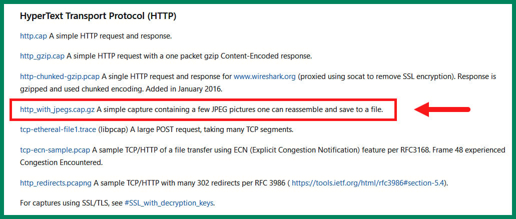
Figure 1.28 – Sample capture file
- Next, open the Wireshark application on your computer, click on File | Open, and select the
http_with_jpegs.cap.gzfile that you downloaded in the previous step. Once the file has opened within Wireshark, you’ll see all the packets and their contents, as shown in the following screenshot:
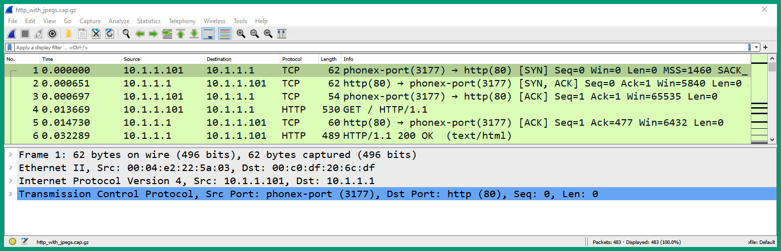
Figure 1.29 – Wireshark user interface
As shown in the preceding screenshot, the upper pane is known as the Packet List pane, which shows all the packets, the packet number, the absolute time from the point the capture started, the source and destination IP addresses, protocols, packet lengths, and summary information. The lower pane is known as the Packet Details pane. When you select a packet, the details and contents of the packet are shown here. There is a third pane called Packet Bytes that is displayed at the bottom of Wireshark. We will not be showing this pane in this example.
- Next, select packet #1 from the Packet Details pane and expand the Ethernet (or Ethernet II) header, as shown in the following screenshot:
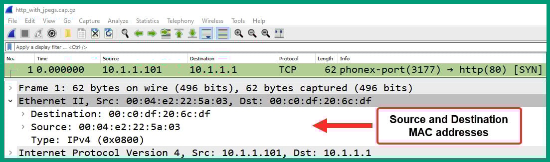
Figure 1.30 – Packet #1 Ethernet header
As we can see, the Ethernet header contains the source and destination MAC addresses, as well as the protocol type of the upper layer (Network/Internet layer).
- Next, expand the Internet Protocol header of packet #1 to view the IP header and its contents, as shown in the following screenshot:
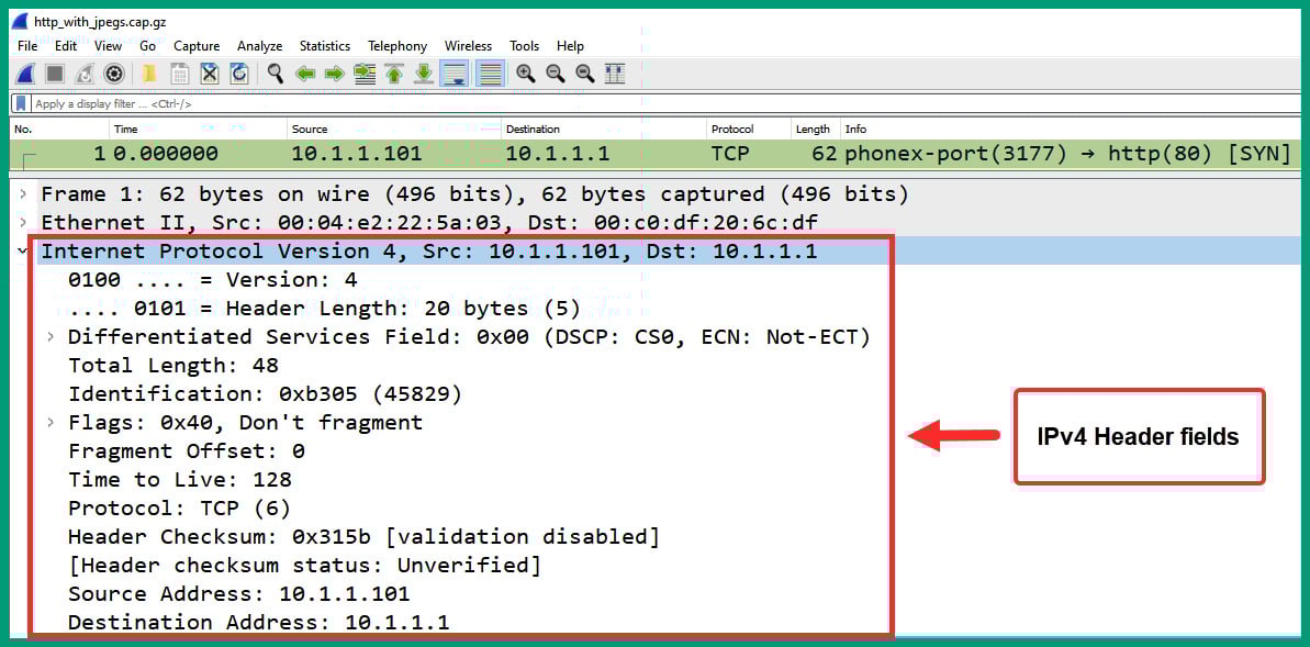
Figure 1.31 – Packet #1 IP header
As we can see, the IP header shows the version, Differentiated Services fields, total length, source and destination IP addresses, and all their fields.
- Next, expand the Transmission Control Protocol header of packet #1 to display its fields, as shown in the following screenshot:
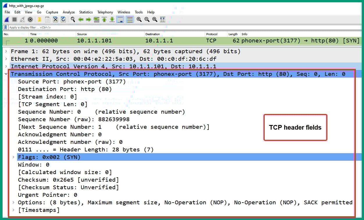
Figure 1.32 – Packet #1 TCP header
As we can see, the TCP header contains the source and destination service port numbers, TCP flag (SYN), sequence numbers, and so on. Notice that Wireshark automatically resolves the application layer protocol based on the service port number.
Important note
If Wireshark does not automatically resolve public IP addresses to hostnames or service port numbers to application layer protocols, simply enable the resolution features by selecting Edit | Preferences | Name Resolution to enable Resolve MAC addresses, Resolve transport names, and Resolve network (IP) addresses.
- Next, select packet #2 from the Packet Details pane and expand the Ethernet header, as shown in the following screenshot:
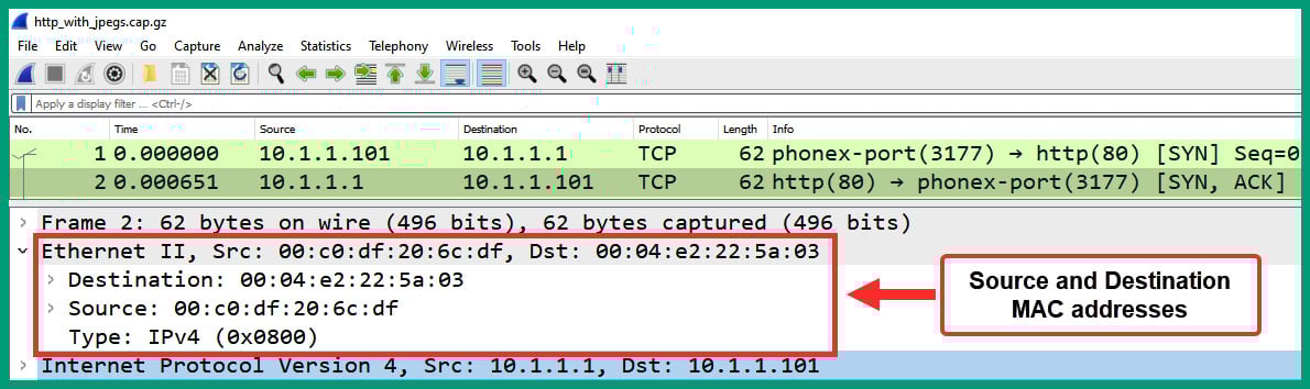
Figure 1.33 – Packet #2 Ethernet header
As we can see, the source and destination MAC addresses are now in reverse order.
- Next, expand the Internet Protocol header of packet #2 to view the IP header and its contents, as shown in the following screenshot:
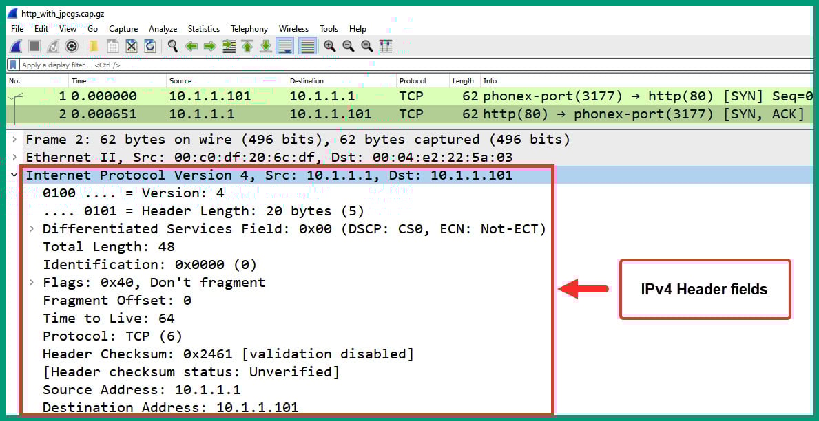
Figure 1.34 – Packet #1 IP header
As we can see, the source and destination IPv4 addresses are in reverse order as the web server is responding to the client.
- Next, expand the Transmission Control Protocol header of packet #2 to display its fields, as shown in the following screenshot:
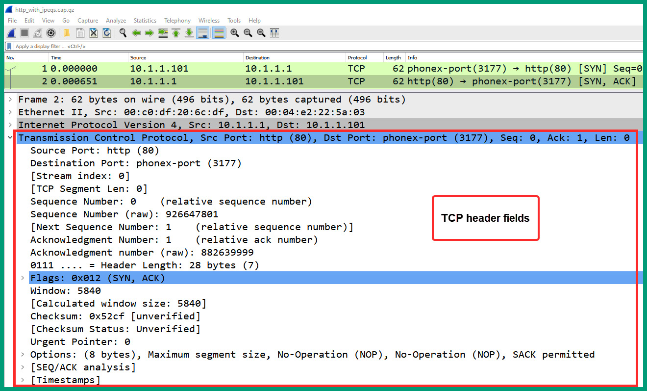
Figure 1.35 – Packet #2 TCP header
As we can see, the source and destination service ports are reversed compared to packet #1. The TCP flag indicates that packet #2 is a SYN/ACK response.
- Next, select packet #3 and expand the Transmission Control Protocol header, as shown in the following screenshot:
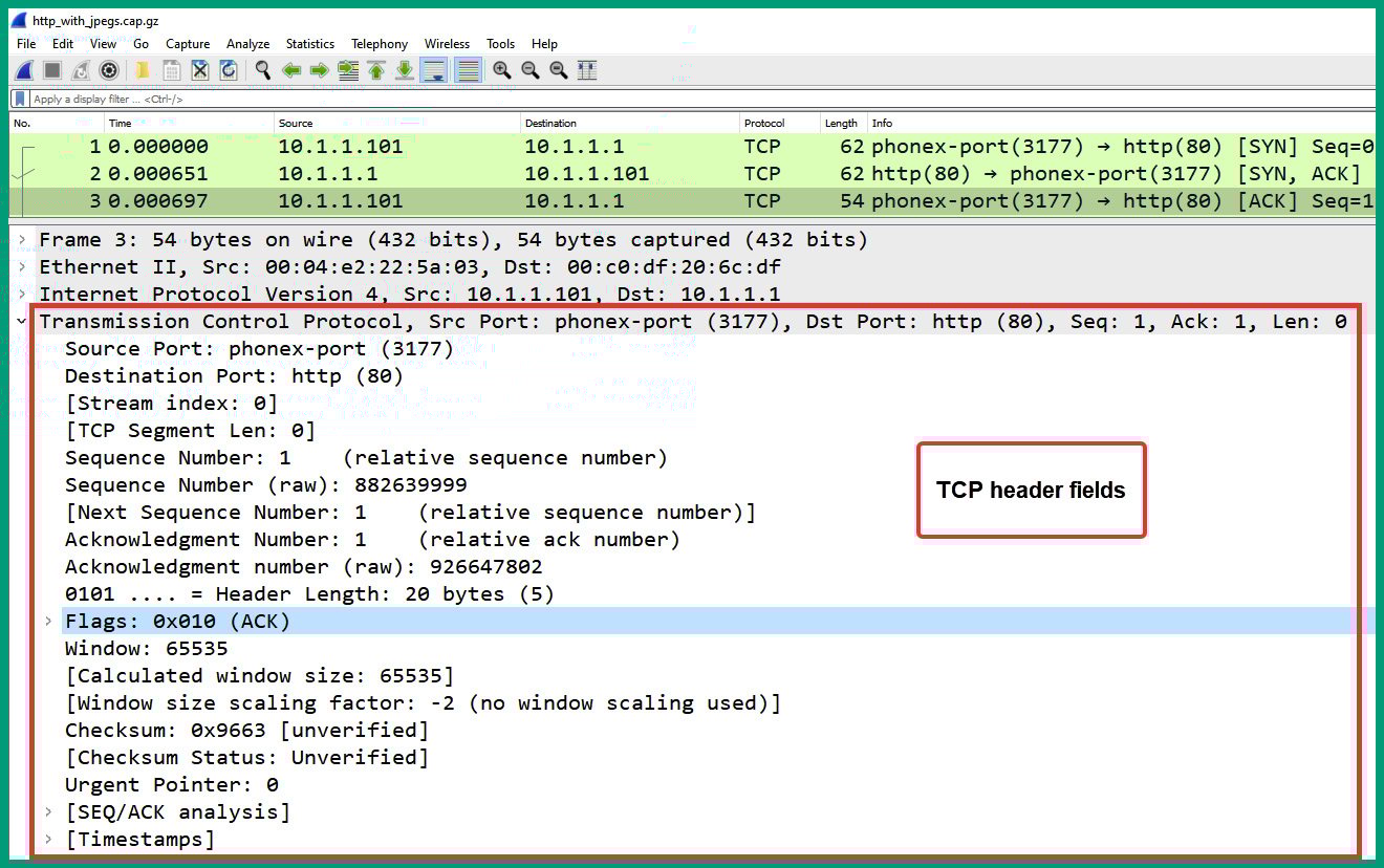
Figure 1.36 – Packet #3 TCP header
As we can see, packet #3 is a TCP ACK that is used to establish the TCP three-way handshake between 10.1.1.101 and 10.1.1.1.
- Next, select packet #4 and expand the Hypertext Transfer Protocol header, as shown in the following screenshot:
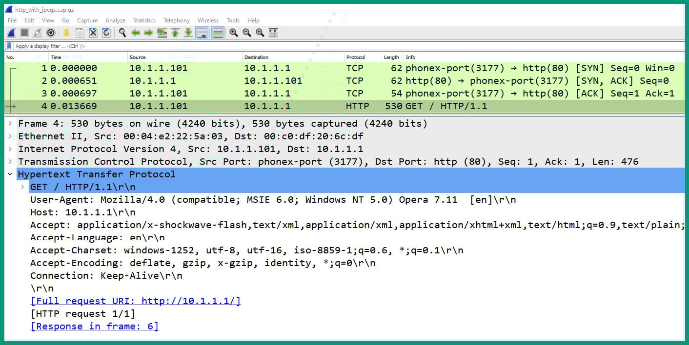
Figure 1.37 – Packet #4 HTTP header
As shown in the preceding snippet, packet #4 is sent from the client device (10.1.1.101) to the web server (10.1.1.1) and Wireshark shows the contents of the application layer protocol (HTTP).
Important note
HTTP is an unsecure protocol that does not provide any security such as data encryption. This means that anyone can view its contents using a protocol analyzer application.
- Next, select packet #5 and expand the Transmission Control Protocol header, as shown in the following screenshot:
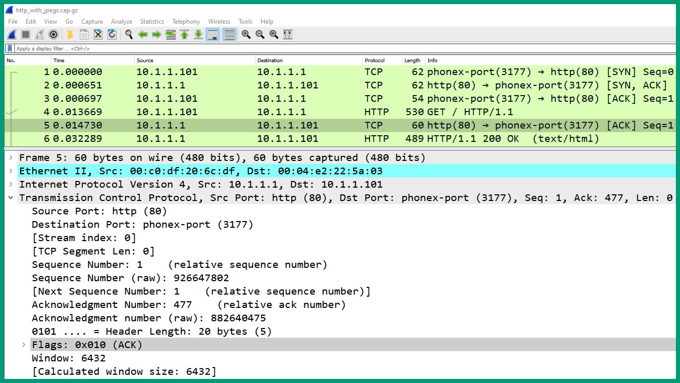
Figure 1.38 – Packet #5 TCP header
As we can see, packet #5 is a TCP ACK packet that is sent from the web server to the client, indicating that the HTTP message was received.
- Next, select packet #6 and expand the Hypertext Transfer Protocol header, as shown in the following screenshot:
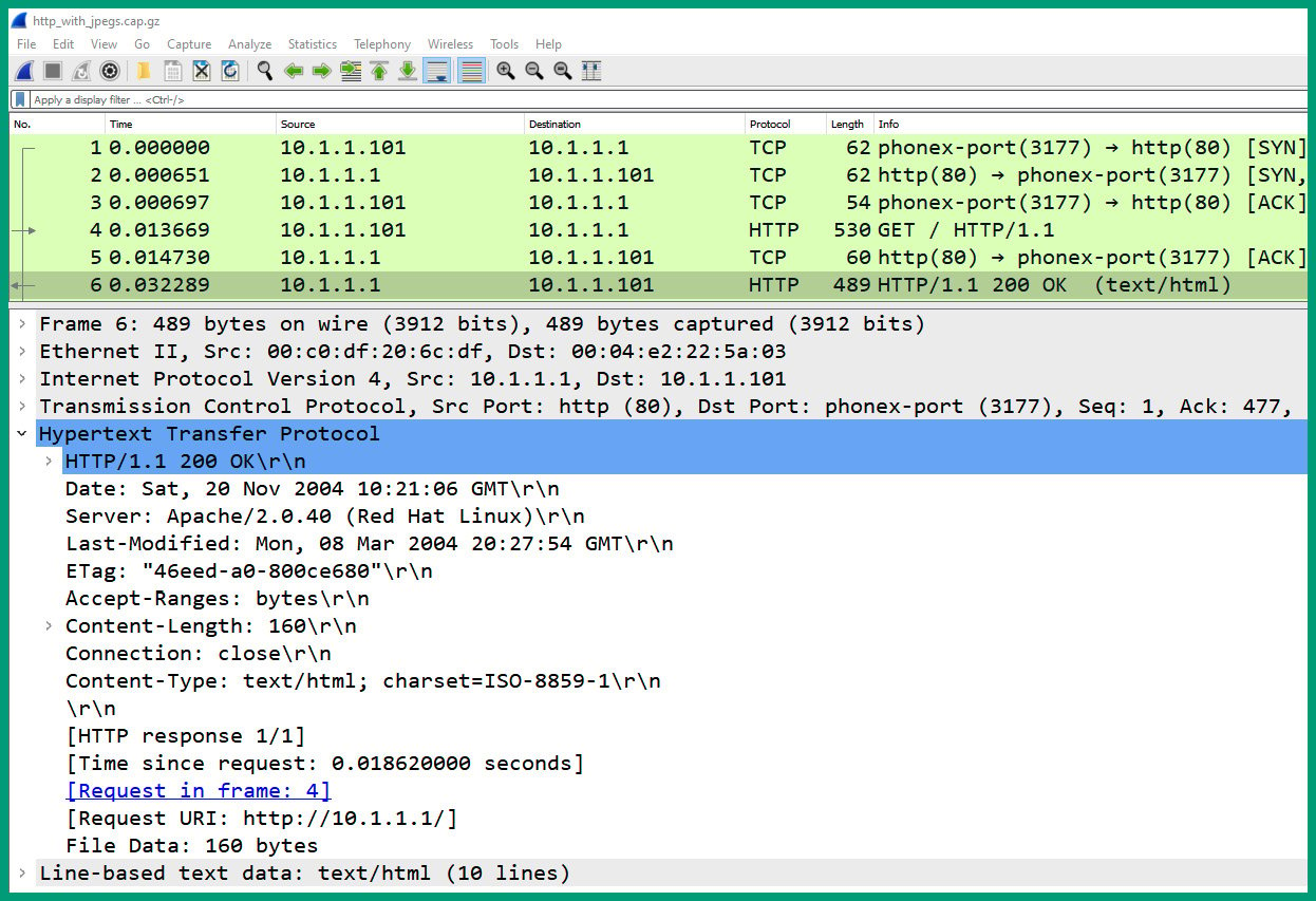
Figure 1.39 – Packet #6 HTTP header
As we can see, the response from the web server is visible using Wireshark.
Having completed this section, you have gained hands-on skills with Wireshark to identify the fields and their values within network packets.
Summary
In this chapter, you explored each layer of both the OSI reference model and the TCP/IP protocol suite. You discovered the roles and responsibilities of each layer and saw their purpose in ensuring messages are delivered successfully between source and destination hosts over a network. Additionally, you can describe, compare, and even contrast the layers between the OSI reference model and the TCP/IP protocol suite. As an aspiring network professional, you have also acquired the fundamental skills of understanding how the encapsulation and de-encapsulation process works between each layer, and even explored the headers of packets using a protocol analyzer application.
I hope this chapter has been informative for you and is helpful in your journey toward learning about networking and becoming a network professional. In the next chapter, Chapter 2, Network Topologies and Connections, you will discover various network topologies and common network types that are used within many organizations and service providers around the world.
Questions
The following is a short list of review questions to help reinforce your learning and help you identify areas that may require some improvement:
- A technician has received a ticket that describes some CRC errors that have been detected on the network that are causing poor network performance for the users. Which of the following layers should the technician begin the troubleshooting process with?
A. Transport
B. Internet
C. Physical
D. Data Link
- Which of the following layers of TCP/IP is responsible for assigning the logical addressing to the PDU?
A. Network
B. Transport
C. Internet
D. Network Access
- Which of the following is a connectionless protocol?
A. HTTP
B. TCP
C. LLC
D. IP
- Which of the following layers is not part of the OSI model?
A. Application
B. Internet
C. Network
D. Transport
- Service port 25 is associated with which of the following protocols?
A. SMTP
B. DNS
C. HTTP
D. SSH
- Which of the following layers of the OSI model is responsible for data encryption?
A. Network Access
B. Application
C. Session
D. Presentation
- How many bits are there within a MAC address?
A. 49
B. 32
C. 48
D. 128
- How many bits are there in an IPv4 address?
A. 32
B. 49
C. 128
D. 16
- Which of the following layers is responsible for placing the data in the actual network media?
A. Internet
B. MAC
C. LLC
D. Network
- Which of the following is not a valid MAC address?
A. 0c:2d:c4:41:8b:66
B. 3d:f2:51:bf:40:b9
C. 4f:95:I5:b2:68:ca
D. c5:fe:00:4f:73:e6
Further reading
To learn more about network port numbers and protocols, check out https://hub.packtpub.com/understanding-network-port-numbers-tcp-udp-and-icmp-on-an-operating-system/.
