


 Download code from GitHub
Understanding Home Automation Systems
The idea of this chapter is to present what a home automation system is by giving a brief history and background of how it started and how it evolved over the years. Here, we will highlight and discuss the benefits of having an automated home. We will also get an overview of the main components used in the system, and discuss the role of each one of them so that you can understand how a home automation system is structured.
Real examples of home automation will be provided in this chapter, and you will learn about my experiences over the years with different home automation systems and how they were implemented. I will conclude the chapter by detailing how my home is configured nowadays and ideas about the cost and materials used on it. This will help you to think about what you will need and how much it will cost to implement your system.
In this chapter, we will cover the following main topics:
- Overview of home automation systems
- Benefits of having an automated home
- Home automation structure
- Example of a real home automation system
Technical requirements
For this chapter, it is good to know about client-server architecture to understand how a home automation system is configured but don’t worry if you don’t, since we will cover this content in the next section. Also, you will be able to learn about Message Queuing Telemetry Transport (MQTT) more effectively if you have some understanding of communication protocols broadly speaking. Knowledge of some electronic components will help you to understand the sensors and actuators topics in more detail.
Overview of home automation systems
Home automation became available and accessible to people when the industry started to provide devices that allowed some kind of sensor and actuator to be applied at home. The first devices of this kind I heard about were the X10 devices.
The X10 technology was created in 1975 by a company called Pico Electronics and became commercially available around 1978. Essentially, it uses the power line available in every home to turn lamps and appliances on and off. Initially, with the limited availability of computers, these so-called home automation systems used architecture that provided limited use. Limited because the control was not centralized and didn’t allow really smart automation to be created. Besides that, there was not much hierarchy in the system, meaning that controllers could communicate with actuators and sensors too. The diagram in Figure 1.1 shows more about the possible configuration used at that time:

Figure 1.1: Early automation systems configuration
As can be seen in Figure 1.1, there was not much hierarchy in the system, which meant that controllers could communicate with actuators, but sensors could also communicate with them too.
When computers became more popular, software such as HomeSeer, Xtension, and Indigo were created to support the X10 technology. Some X10 computer translators were created so that the architecture allowed more intelligence to be added by using a centralized system, as can be seen in Figure 1.2:

Figure 1.2: Recent configuration
Even with a computer, the X10 system was still limited because it was wire dependent, and the number of addresses was limited to 256 devices, meaning 16 houses or rooms, each one with 16 units or devices. Each address is configured manually in the module using two rotatory switches, one from the module’s house varying from A to P and the other for the unit varying from 1 to 16. As an example, a house or room in a home can have the letter A to designate it, and a unit such as a coffee maker is assigned the number 1, so the rotatory switch for an X10 Appliance module will have the configuration A1. Other units in the same house A can have another number assigned to them, such as 4, so the rotatory switch in another appliance or lamp module will have the configuration A4. If the house or room is configured as the letter P, we can have a rotatory switch configured from P1 to P16 to represent 16 different units.
My first experience with the X10 protocol was around 2006 when I acquired a device set composed of two lamp modules (PLM03 and RLM20), an appliance module (PAM02), and a two-way power line interface (PSC05). At the same time, I saw an application note (AN-236 - X-10 Home Automation using the PIC16F877A) and decided to build a task controller using it, adding a temperature sensor and a local relay, and excluding the X10 controller/receiver which was replaced by the PSC05 module acquired. I was able to run my first home automation system, which just had actuators that were turned on and off based on pre-configured timer events embedded in the software application I created. The components of my first home automation system are presented in Figure 1.3:

Figure 1.3: My first home automation system using X10 technology
Figure 1.3 presents the X10 task controller at the top showing a 16X2 LCD module, and underneath it (not shown in the picture) is the Programmable Interface Controller (PIC) microcontroller. The task controller connects to a two-way power line interface module (the white box in the middle) through the white cable, which is connected to a power line. This power line interface sends and receives commands to and from the lamp module (the white box on the left) or the appliance module (the white box on the right).
On top of this X10 task controller, I was able to hack a WRT-54G router from Linksys (seen in Figure 1.4) and add two serial ports to it. Later, I connected it to the X10 controller and turned it on, commanded by a Google Android application created specifically to do it:

Figure 1.4: Linksys router modified to be used as part of my home automation system
Figure 1.4 shows the router with the two DB-9 standard connectors for the RS-232 serial port. One of these serial ports was used to connect to the other DB-9 connector located in the X10 task controller and allow my system to be accessible using wireless communication.
In 2012, I bought my first Wi-Fi module from Particle (https://www.particle.io/), where I was able to replace my original PIC-based X10 controller with a small and powerful piece of hardware. Looking at Figure 1.5, my most up-to-date and optimized system using X10 technology is presented:

Figure 1.5: Latest configuration of my X10 home automation system
Figure 1.5 shows the tablet with my Google Android application (HomeAutomationApp) running, the X10 modules presented previously, and the Particle Wi-Fi module board (former Spark Core).
As can be seen over the years with my X10 system, I had to create my own hardware initially, hack a router, and create an embedded software for the task controller (PIC and Particle) and an Android application so the system could work as desired. Even then, my home automation system was very limited, wire dependent, and hard to maintain.
Based on the evolution of my home automation system over the years as mentioned in the previous examples, and lots of hardware and software programming developed, I felt something else was missing. In 2020, I was interested in learning more about current home automation systems. And it was at that time that I discovered a configuration that changed and made my life easier. This configuration was based on the client-server architecture and is introduced in Figure 1.6:

Figure 1.6: Client-server architecture
As demonstrated in Figure 1.6, the client-server architecture is configured as clients connect to a server via wireless communication, and the server manages the communication requests by taking some actions, including sending commands back to clients. This is the architecture that I will explore in the remainder of this chapter.
Now that we have an overview of home automation systems and its architecture, let’s look at their benefits.
Benefits of having an automated home
Before we move on to the explanation of the architecture of a home automation system used nowadays and the one that is being used in my home, let’s explore and highlight some of the benefits and advantages of having an automated home.
Saving time
The first benefit that can be highlighted is that an automated home will save you time. Think about a simple application; you can remotely turn on or off a lamp or an appliance using your cell phone or a voice assistant device, so you do not need to walk to the switch to do it. This can sound strange if the switch is close to you but think about the idea that you have to do this kind of thing many times a day. You can include, for example, an automation routine that can be triggered to turn a device on or off when a particular time of the day is reached. This can save you considerable time during your day if multiple similar routines are configured, and you do not need to go to each device and turn it on or off.
Feeling comfortable
Having an automated home will bring you some convenience. A good example of that is the automation routine I implemented in my home where the front lights turn on when at sunset, and after four hours, they turn off. This is very helpful for me because there is no public illumination in my street, so it is very dark at night. The lights help to illuminate my house numbers in case someone visits me for the first time at night.
Another example is when I wake up at night to take care of my youngest son, the movement sensor turns on a small light in the aisle so we can see where to go since the master bedroom is on the other side of the house.
Another good example is setting up a scene in your bedroom where you can dim the lights, and turn on the fan and TV automatically if it senses you are in your bedroom at a certain time of the night.
Important note
An automation routine is a resource used in a home automation system to automate certain actions using the devices installed in your home. These routines are configured to be triggered when certain events happen. An event can be different situations, such as sensor status or the time of the day, for instance. We will talk more about automation routines in Chapter 5.
Saving money
An automated home will save you money mainly by configuring some devices in your home to the savings or eco mode. You can configure these modes in the device or implement an automation routine that can emulate it. The example I gave in the last section, where the front lights are turned on and off at night, could save you some money on your electric bill rather than them staying on for the entire night and you having to turn them off in the morning. Another example, depending on the load and how much energy it consumes, is leaving a device turned off when it is not needed. This will be a more significant saving than the first example. A good example of this is the Heating Ventilation and Air Conditioning (HVAC) system that can be turned off when no one is at home.
Being safe
An automated home can help you to protect and make your house safer. Door sensors can be installed on the main doors of your house, and alarms can be configured to make sounds or announce people entering. This can prevent people from entering without your consent or the opposite, prevent people such as your kids from leaving the house without your awareness. Sensors can also be installed on windows to improve protection against burglars or thieves. Cameras can also be activated when door sensors are triggered, offering remote monitoring if you are not at home.
These are just a few benefits of having a home automation system in your home. You will probably find others during or after reading this book.
In the next section, we will review in more detail the structure of a home automation system when you will be able to understand the components that can be grouped to create it.
Home automation structure
After some background information about different architectures used for home automation and also aspects to motivate you to build your home automation system, it is now time to detail each component. The architecture that I will focus on in this book is the one that I have implemented in my home, so it is proven that it works. This architecture has the same idea of the client-server presented previously in Figure 1.6, but here, I have added the proper names and identifications of each part of the system. This architecture is presented in Figure 1.7:
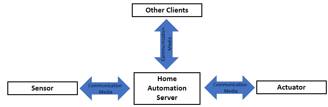
Figure 1.7: Home automation system architecture explored in this book
This architecture assumes you have a Wi-Fi 802.11g or above router in your home, but this router does not necessarily need to be connected to the internet unless you want to access your home automation system remotely.
In the following subsections, each part of the system presented in Figure 1.7 is discussed in detail.
Home automation server
The home automation server is the central connection or the heart of a home automation system. It centralizes all the communication received from the sensors and transmits them to the actuators. It contains all the logic of the automation created by the user and also allows the configuration of new devices to be added to the system. The server also manages other connections to the system, such as applications that can be connected to it using a cell phone running Google Android or Apple iPhone Operating System (iOS).
The home automation server is composed of two distinct parts: hardware and software. Depending on the level the user wants to go in the system, the hardware can vary from a desktop or notebook to their own design. It will all depend on the cost and time invested in creating or building the server. Due to the availability of open source hardware, I recommend that the system is implemented using an off-the-shelf device. I strongly recommend that a board such as a Raspberry Pi 4 is used, but if you already have an old computer or any other hardware that can run Linux, it could be used. Another commonly used hardware option is the Intel NUC platform.
The home automation server should be able to run Linux or some other popular operating system such as Windows or macOS. Another requirement is that the server should support Wi-Fi 802.11n wireless protocol or above. Currently, I’m using a Raspberry Pi 4 Model B 2019 with 4 GB of RAM in my home automation system. This hardware will be the focus of the home automation server used in this book.
Speaking about the software component of the home automation server, you can try to build your own software to manage the role of the automation server. The only advantage of this method is the learning process that you will go through by creating it. I must confess that I learned a lot when I implemented the X10 task controller. The original software from the microchip application was written in Assembly and I migrated it to the C programming language. Later, I migrated the C application to the Arduino-like format used in the Particle Wi-Fi board. This learning process was useful for me in other aspects of my job and career, but nothing compares to the variety of home automation software available today.
As the name of the book somehow anticipates, Home Assistant (https://www.home-assistant.io/) is the software used in the home automation server adopted in this book. The reasons I chose Home Assistant to use at my home were because of the documentation, support, integrations, and add-ons it gives to the users. Home Assistant is one of the most used open source software for home automation projects and supports Linux, Windows, and macOS operating systems. It supports lots of add-ons that allow the system to be expanded, as will be explained in Chapter 7. Another open source software that can be used in home automation systems is openHAB (https://github.com/openhab).
One paradigm followed by this book is that you are free to choose your sensors and actuators to be integrated into your system, which is one of the reasons for using Home Assistant. In this case, the home automation server software should allow easy integration of sensors off the shelf and even sensors you decide to create. There are some home automation software and systems that interlock the hardware and software in their architecture, not allowing other types of devices to be used in your home automation system different from the architecture they offer. In my opinion, this kind of approach prevents the user from being free and flexible in the choice of sensors and actuators. The most popular systems of this nature are Insteon, Lutron, and SmartThings, owned by Samsung Electronics. In this regard, Home Assistant supports different ways of integrating the different sensors and actuators so it will not hold you to some particular platform or architecture. This free choice will certainly contribute to lowering the cost of your system since you will have more options of devices to select.
In general, I recommend that you choose compact hardware so it can easily be installed in any place in your home, preferably somewhere hidden, and then eventually, you have to be physically connected to it using a computer video screen. Once the home automation server is installed and initially configured, you will not need to access it physically anymore unless it presents some issue or if you want to install some other software on it that is not able to be installed remotely. If the idea is to use the hardware only as a home automation server, all configuration, automation, and any other new setup can be done remotely via a web browser. It is worth mentioning that the location for the installation should not be too far from the main source of the Wi-Fi router used in your home. If you need more reliability in your home automation server connectivity, it is recommended that you use a wired connection such as Ethernet (IEEE 802.3) connected to your Wi-Fi router.
In my home, the home automation server is installed at the back of my computer video screen using 3M VHB Scotch SJ3550 Dual Lock adhesive tape. Figure 1.8 shows this installation:
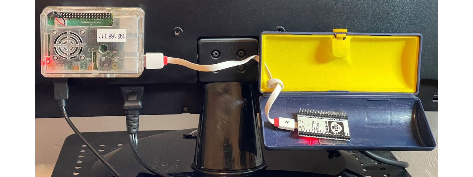
Figure 1.8: My home automation server
Figure 1.8 shows the home automation server using Raspberry Pi on the left and also an ESP32 Wi-Fi/Bluetooth module (upside down) on the right used in the five-zone temperature logger explained in Chapter 10. In the next chapter, we will introduce Home Assistant as the software for the home automation server and will guide you to install it on a Raspberry Pi 4 as the hardware used for this server and used in this book.
Sensors
The sensors and actuators are what bring life to your home automation system and allow you to create automation, configuration, and integration using Home Assistant.
Sensors are electronic devices that contain certain electronic components able to measure or detect some measurement or status of what or where they are installed. They always provide an output signal that is used as an input signal to the home automation server to inform it about what the sensor is detecting.
The sensors can be generically classified into two types: analog and digital. Analog sensors are the ones that can provide discrete values of output signals. In other words, these sensors can have multiple values to express the information being measured. A temperature sensor, for example, is an analog sensor that can express in its output different measurements about each temperature value captured or sensed by it.
A digital sensor provides binary information in its output, meaning two states which can vary depending on the sensor. The common states associated with these sensors are turned on, turned off, open, and closed. These sensors can also inform about two values in reference to a threshold. In this case, one state will be above the threshold, and the other state will be below the threshold. One good example of a digital sensor used in home automation systems is a door sensor. It is basically composed of an electronic component called a reed switch, which works as a magnetic switch to provide two states: closed, to inform the door is closed, and opened, to inform the door is opened.
Table 1.1 lists some examples of sensors commonly used in home automation systems, including type and measurement sense:
|
Sensor |
Type |
Measurement |
Typical values |
|
Door sensor |
Digital |
Door status |
Open, closed |
|
Motion sensor |
Digital |
Motion status |
Motion detected, Motion not detected |
|
Temperature/humidity sensor |
Analog |
Temperature/humidity |
Various, depending on the temperature or humidity range measured by the sensor |
|
Light sensor |
Analog/digital |
Light intensity |
Light on, light off. Light intensity values, depending on the range measured by the sensor |
|
Energy meter sensor |
Analog |
Power consumption |
Power values according to the sensor range |
|
Gas sensor |
Analog/digital |
Gas status/value |
Gas on, gas off. Gas intensity values, depending on the range measured by the sensor |
|
Smoke sensor |
Digital |
Smoke status |
Smoke/fire on, Smoke/fire off |
Table 1.1: Examples of sensors used in home automation systems
A general block diagram of a sensor for home automation is demonstrated in Figure 1.9:
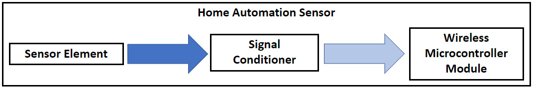
Figure 1.9: Home automation sensor block diagram
It is important to understand each one of the blocks discussed, to help you put together the parts and components to build your own sensor, which is discussed in Chapter 3 of this book.
The first component part of a sensor, as seen on the left of Figure 1.9, is usually an electronic component able to capture some measurements related to the environment where it is installed. We called it the sensor element. Within the electronic components used, some of the following examples can be found:
- Reed switches/magnetic switches: These are electromechanical components composed of two ferromagnetic metallic plates hermetically sealed by a glass enclosure. These plates move up to contact one to the other when a magnetic field is applied. They provide two statuses, open and closed, and are commonly used in door sensors.
- Passive Infrared (PIR) sensors: These are electronic components that are able to detect the changes in infrared radiation when something crosses their field of view. The sensor converts these variations in voltage changes to be formatted as motion changes. Despite the voltage variation being an analog value, the application (motion sensors) where these sensors are used only considers the digital variation of it. They are used in motion sensors.
- Light Dependent Resistor (LDR) sensors: These are electronic components that vary their resistance when light is applied. They provide an analog value according to the light intensity variation. They are used in light sensors.
- Thermal Resistors (thermistors) and temperature measurement Integrated Circuits (ICs): These temperature sensors are electronic components built with different technologies to provide an analog value associated with the temperature to which the sensor is submitted. In the past, resistors were made with the purpose of changing their values with the temperature, or thermistors were used, but today different electronic components manufacturers are using ICs as sensors, which provide much more reliability and measurement range. As the name suggests, they are used in temperature sensors.
The next block part of the sensor, as seen in the middle block of Figure 1.9, is the signal conditioner. These circuits are usually required to modify the signal generated by the sensor. This signal from the sensor could require some voltage level conversion, or in a lot of situations, the signal coming from the sensor has small voltage or current variations, so it needs to be amplified. Also, this same signal could be generated with a lot of noise and needs to be filtered. Signal conditioner circuits can perform the filtering process to make sure the signal will be cleaned and well-interpreted by the upstream circuit.
In summary, signal conditioner circuits translate the information from the electronic sensor components into something understandable by the next part of the sensor, the wireless microcontroller module. The signal could be conditioned to be read by the microcontroller as a digital binary or analog input. In some cases, as we will see in Chapter 3, the signal conditioner could encode the signal to generate some digital communication standard to interface to the microcontroller. These standards can be in different formats, but the most popular are serial communication interfaces such as Inter-Integrated Circuit (I2C) and Serial Peripheral Interface (SPI).
The last block of a home automation sensor (the right block in Figure 1.9) is the wireless microcontroller module. This module receives the information translated or converted from the sensor by the signal conditioner circuit and sends it via wireless to be managed by the home automation server.
If you are curious enough to open one of the home automation sensors, you may find a shield in the format of a metallic box where this wireless microcontroller electronic component is located. In some cases, to reduce the circuit footprint and cost, these microcontrollers are found without the metallic shield box. Actually, in most cases, these electronic components are called System on Chip (SoC). They are large-scale integrated circuits that combine a microcontroller and wireless radio in one single chip. Due to this large-scale integration, few external electronic components are required, keeping the size of the entire circuit small, which is highly desirable when it comes to a home automation sensor.
These SoCs are commonly used by many hobbyists to implement various kinds of Internet of Things (IoT) projects. The most popular of these components are from a Chinese component manufacturer called Espressif Systems. Espressif manufactures the ESP8265, ESP8266, and ESP32 SoCs. The main reasons for the mass utilization of these SoCs are, in my opinion, the easy availability of them in the market, affordable cost, and an active community of developers. You can easily find wireless communication modules based on the ESP8266 and ESP32 from the biggest world-famous dealers costing around $10 or less. You can also develop and deploy software programs using Arduino sketches via the Arduino Integrated Development Environment (IDE). This means if you know how to develop a program for Arduino using the different software libraries available, you should be able to develop applications using ESP8266 and ESP32.
In the next chapters, we will build some projects for sensors, and we will use the ESP8266 and ESP32 Wi-Fi-based modules to do it.
Actuators
The actuators receive the information from the home automation server and provide a type of output, such as turning on or off a switch connected to an appliance, for example. It can also receive information to send a command to simply turn a lamp on or off or change its color or brightness.
Likewise as the sensors, the signal sent to an actuator output can be digital or analog. Turning a switch on or off is a good example of digital binary information sent to an actuator. Other examples of actuators can be given according to Table 1.2:
|
Actuator name |
Type |
Status |
|
Switch |
Digital |
On, off, and other intermediate states |
|
Lamp |
Digital/analog |
On, off (digital) light intensity, light color (analog) |
|
Alarm sound |
Digital/analog |
Sound on/sound off (digital) sound levels, sound tones (analog) |
Table 1.2: Examples of actuators
The block diagram of an actuator follows the opposite sequence found in a sensor and is configured according to Figure 1.10:
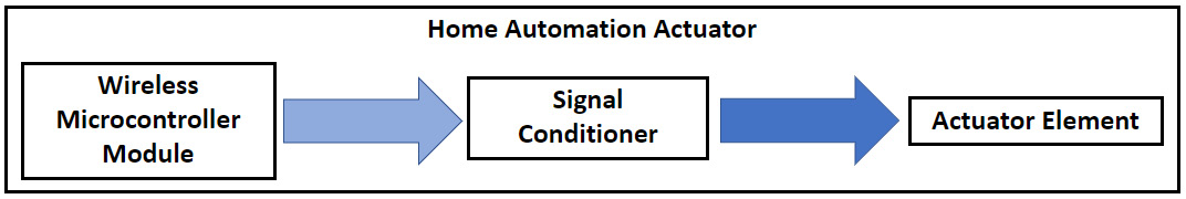
Figure 1.10: Home automation actuator block diagram
The wireless microcontroller module referenced in Figure 1.10 in the left block is usually the same found in the sensors and, again, mostly the ones manufactured by Espressif Systems, ESP8266, and ESP32. It receives information from the home automation server and translates it into an output command that will ultimately control the actuator element. This command could be a voltage level representing a binary signal, an analog signal, or even a serial digital communication protocol such as I2C or SPI.
The wireless microcontroller module becomes very versatile since it provides different input/output pins, serial interfaces, and other features and peripherals, allowing multiple combinations of electronic components and circuits. These can lead to sensors and actuators or more than one sensor element being used in the same enclosure. You can build a sensor that can be used for temperature and motion detection at the same time using just one wireless microcontroller, as can be seen in Chapter 3.
The signal conditioner circuit (the middle block in Figure 1.10) has the same idea used in the sensors, but in this case, it is conditioning the output signal sent by the wireless microcontroller module. It could be a voltage or current level converter, for example. This circuit is required in most cases due to a wireless microcontroller module limitation preventing the end actuator element from working properly.
The actuator element presented in Figure 1.10 on the right is what promotes the final effect when the home automation actuator is triggered. It is an electronic component or circuit. The simplest example of an actuator element is represented by an electronic component called an electromechanical relay. Combined with a conditional circuit, it allows direct control from a wireless microcontroller module. The relay converts an electronic binary signal into a mechanical switch command. So, the relay is an electronically controlled switch. This switch attached to an outlet can connect or disconnect the voltage from it, allowing it to turn an appliance on or off, for instance. Figure 1.11 shows a typical circuit used in a relay-based actuator and also a photo of a commercial actuator where each block of it is represented:
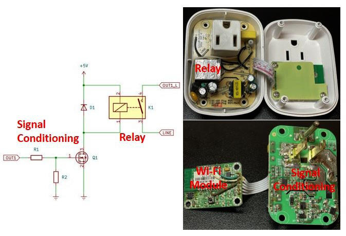
Figure 1.11: Circuits found in a home automation actuator
Communication media
Communication media is the environment or infrastructure where the home automation server talks to sensors, actuators, and other applications or devices that will connect to your system. It is important to understand how the communication media is structured and works so you can choose the proper media to implement your system and configure it by knowing which parameters to set up.
Wired systems
Commercial home automation systems can use wired media to communicate. These systems came in different formats, such as structured cabling using Unshielded Twisted Pair (UTP), coaxial, and fiber optic cables. Usually, they attend to some specific types of systems such as phones, cable TV, multimedia, and computers. As a disadvantage, this media type somehow limited the expansion of the systems and was not designed to automate a home, just to allow some type of devices to share or communicate using the same media. It is also not flexible since the communication node is available where a cable is present. Among the advantages of wired systems is the reliability and communication speed that some technologies can offer such as fiber optic cables.
As highlighted previously, one good example of wired systems targeting a home automation system was the X10 technology. The X10 uses the power line available in each home to encode binary information, and devices attached to the power line can decode this information and process it accordingly.
Wireless systems
Wireless systems are much more commonly used for home automation systems. The most common wireless protocols used are Wi-Fi and Zigbee. Wi-Fi (IEEE 802.11) is well-known, supported, and available. It works under the 2.4 and 5 GHz operating frequencies. When implemented in the sensors and actuators, it allows direct communication to the Raspberry Pi automation server, which also implements this protocol. The issue with the Wi-Fi wireless protocol is that it was not developed exactly for home automation and IoT systems. The power consumption in the Wi-Fi protocol is high, which in some situations prevents it from being extensively used in battery-powered sensors, for example.
The Zigbee wireless protocol (IEEE 802.15.4) is more applicable for home automation systems in some circumstances. It operates under the 2.4 GHz Industrial, Scientific, and Medical (ISM) band. It was created with a low overhead in the communication layer (low bandwidth), allowing efficiency when it comes to small-scale projects. It also has low-power radios compared to Wi-Fi, so it is more suitable for battery-powered applications. Due to the simplified communication stack, the Zigbee protocol can wake up from low power modes much quicker compared to the Wi-Fi protocol, so some sensors, such as door sensors, can react faster to events. The drawback of using the Zigbee protocol is that it is not as available as Wi-Fi, and when using commercial sensors, usually a specific router is required to add another layer of communication or device to the communication infrastructure, which adds costs and more configuration to be done in your home automation system. To date, I have not felt the need to add any infrastructure related to the Zigbee protocol in my home automation system. You have to evaluate your applications, and if you need to use lots of battery-powered sensors, it is worth considering Zigbee wireless communication in your system.
Another wireless protocol used for home automation systems is Z-Wave. It is a proprietary technology owned by the Silicon Labs company. It uses a mesh network arrangement, allowing devices to communicate among themselves. The mesh network can expand the range of the network and become stronger since it will continue to work if one node or the main node fails. Another advantage of Z-Wave wireless is that it operates under the sub-1 GHz frequency range band, which is less congested than 2.4 GHz, so it allows it to be low power, long range, and with less Radio Frequency (RF) interference.
Finally, I would like to mention the Bluetooth Low Energy (BLE) wireless communication protocol. This Bluetooth variation has many advantages related to home automation systems. Some of them are power consumption, security features, interoperability, ease of use, and low cost. These features, combined with Wi-Fi, can create other powerful communication protocols such as the recently launched Matter, which we will cover in Chapter 11.
With regards to wireless systems, it is worth commenting that the communication range is one aspect that should be considered. The range of these wireless devices can communicate is up to 50–100 meters inside a home, so it is good to evaluate where your wireless router will be installed so the Wi-Fi signal can cover your entire house. Depending on the configuration, you may need to use repeaters spread throughout your house. Another aspect to consider is that the wireless signal can be attenuated differently depending on the material your house is built. It means that a wall made of bricks and cement can attenuate more the signal compared to a wall made of wood. Make sure your entire house has enough wireless signal coverage; otherwise, your system will not work properly.
Important note
The wireless communication range of sensors and actuators is limited by the small size of the internal circuits, including the antenna, which is usually made as part of the Printed Circuit Boards (PCBs).
The communication media used in this entire book is the wireless Wi-Fi network. As mentioned, it is not required that this Wi-Fi network be connected to the internet unless you need to access your home automation system remotely.
Protocols and brokers (MQTT)
Protocols and brokers define the entire home automation structure and what language the devices in the system use to talk to each other. A protocol implements a set of commands, configurations, and communication schemes that allow one device to exchange information better with another. It can implement some sophisticated mechanisms to improve reliability, such as error correction, package retransmission, and so on.
In the sequence, I will provide details about a wired (X10 protocol) and wireless communication protocol (MQTT). MQTT will be very important to understand because it will be used in most of the future chapters of this book.
The X10 protocol
The X10 wired protocol works as follows. In the USA, the AC typically has a 60 Hz frequency and is represented by a sine wave crossing zero with a peak of 120 V. Each time that the current crosses the zero, a binary representation is encoded to the sine wave to represent ones and zeros. The binary 1 is represented by a 120 KHz burst with a 1-millisecond duration, and a binary 0 is represented by an absence of the 120 KHz burst after the crossing. In the three AC phase distribution systems, these bursts should be transmitted in each phase spaced 2.778 ms from each other.
One basic message encoded in the X10 format has 11 cycles of a power line. The first two cycles represent a Start Code (b1110), the following four cycles are the House Code (1…16), and the last five are a Number Code (1…16) or a Function Code (on, off, and so on). This complete block, including the Start Code, House Code, and Key Code, should always be transmitted twice spaced by three power line cycles between them. In order to improve reliability, the X10 protocol also states that the House Code and Key Code should be decoded as a complement form on alternate half cycles of the power line. This means, for example, if no signal is transmitted in the first half cycle (binary 0) then a 1 millisecond 120 KHz burst of the signal should be transmitted in the next half cycle (binary 1). Figure 1.12 explains how it works and also includes a table with the House Codes and Key Codes:
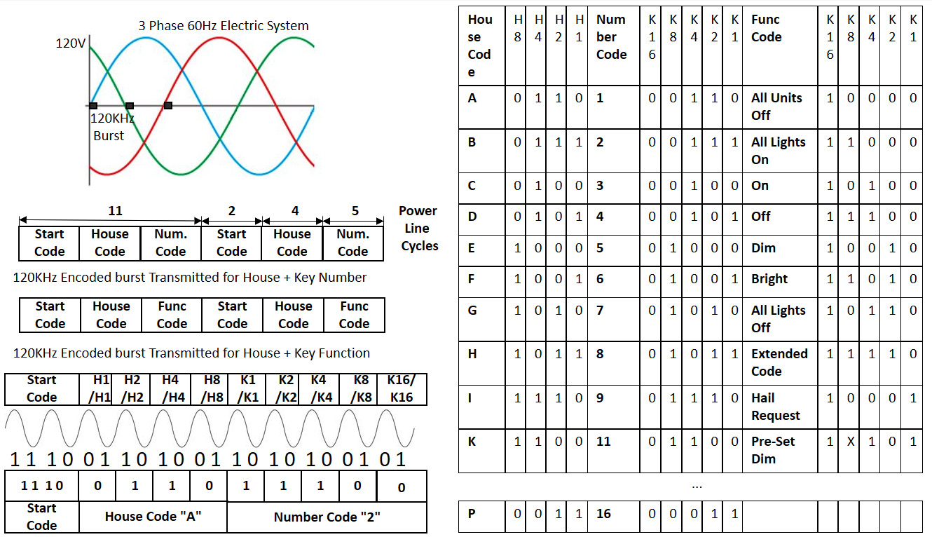
Figure 1.12: Information about the X10 protocol
Figure 1.12 at the very top on the left presents how the 120 KHz is encoded in the three-phase power line system. Actually, this is just a representation since the 120 KHz burst is superimposed on the 60 Hz sinusoidal signal. On the left, in the middle of Figure 1.12, the protocol fields for the House Code/Key Code and House Code/Function Code are presented. An example of how the house address A2 is coded is presented in the bottom left of Figure 1.12. The table on the right of Figure 1.12 presents the numbers used by House Code, Number Code, and Function Code representations.
As you may note, per the protocol specifications, X10 was developed to use in home automation systems, which can address 256 devices minimum with some possibility of extension using an Extended Code. It is relatively easy to implement the software code that implements the protocol. I implemented an X10 task controller using a PIC16F877 microcontroller, which was able to store 16 different events associated with the day and time. It was based on the Application Note (AN) 236 from Microchip (https://www.microchip.com/en-us/application-notes/an236). I used an X10 modem (PSC05) to interface the PIC microcontroller and encode the X10 signals to be transmitted to the power line.
The MQTT protocol
Before going into detail about the MQTT protocol, it is worth mentioning that wireless communication media has different layers. Each layer is responsible for a different level of abstraction of the communication, from how the data received or transmitted will interface to the medium to how the frames or datagrams are organized. It is not the goal of this book to detail these layers since you will not need to implement anything related to the level of the common wireless protocol. The only thing you will need to know for now is how to configure or connect to the Wi-Fi Service Set Identifier (SSID) and password of the router used in your home.
The MQTT message protocol is designed to run above the Wi-Fi or Zigbee communication layers. It was developed to run on IoT devices, meaning lightweight code that perfectly fits small microcontrollers. Besides that, it requires minimal network bandwidth and implements Quality of Service (QoS), improving the reliability of the message delivery.
MQTT is very suitable for home automation systems because it follows the client-server approach discussed previously. It implements an MQTT broker located in the home automation server, and the sensors are the MQTT clients. These MQTT clients are configured as publishers and publish or send information to MQTT brokers. This information is published by the MQTT clients under a specific topic. This topic is commonly the main information that the MQTT client wants to inform all interested parties. The MQTT broker holds the information from the MQTT clients and makes them available. If another MQTT client wants access to the information published by some other client, it subscribes to the topic of interest by sending a request to the MQTT broker. Once the MQTT client is subscribed to the topic of interest, the MQTT broker starts to publish the information under the topic subscribed to the MQTT client that requests the information. Figure 1.13 illustrates how the MQTT communication message protocol works:
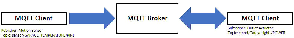
Figure 1.13: MQTT protocol example for garage motion detection
Figure 1.13 shows a simplified example of a garage light motion sensor I implemented at my home. The motion sensor is installed at the top of my garage, and when a motion is detected, it sends a message via MQTT to the broker, which depending on the hour of the day, sends a message to an outlet actuator installed in my garage lights and turns on the lights. It keeps the lights on for 90 seconds, and if no other motion is detected after this time, the MQTT broker sends a message to the outlet actuator to turn it off. We will build this motion sensor together in Chapter 3 and we will see the automation I described using the garage lights actuator in Chapter 5 and Chapter 7 implemented in different ways.
By using the Arduino pubsubclient library (https://github.com/knolleary/pubsubclient), it is possible to implement a software code for an MQTT client. We will use another approach in this book by using software installed in the sensors so you will not need to create your own software to implement an MQTT client. Regarding the MQTT broker, Home Assistant has an integration that allows it to be configured and implemented.
For now, the only important information about MQTT you should know besides the basic information provided previously is some parameters that need to be configured on the MQTT client or server:
- MQTT Host IP: This is the IP address used to set up the MQTT broker.
- MQTT Port: This is the port used to connect the MQTT service. A typical value is
1883. - Topic: This is the name used to identify the topic.
- Full Topic: This is the full name used with the topic to identify certain classes of devices.
More information about the MQTT protocol can be found on the project's web page (https://mqtt.org).
User interface and other clients
The user interface is a component part of the home automation server, which allows the end user to interact with and configure the home automation system. In the case of this book, the user interface is implemented by Home Assistant.
The other clients are external devices that are not necessarily a direct part of the home automation system but can be used to access the automation server and use the Home Assistant user interface to control or configure different devices in your home. Some examples of these clients are other computers or your smartphone connected to your home wireless network.
Note
Your smartphone can be used to access the system remotely and as a sensor to indicate you are at home.
In this section, we were able to understand what the components of a home automation system are. We also explained how these components work and how they can be connected and used as intended.
In the next section, I will provide you with an idea of how my home automation system is distributed in terms of sensors and actuators. You will learn about how many devices I have, where they are located, associated costs, and so on. I hope that this motivates you to create your own.
Example of a real home automation system
In this section, the idea is to give you an overview of what a real home automation system looks like. I will do this by providing details about my own system.
History
I started to build my current system in 2017 when I first purchased my first four Wi-Fi actuator plugs. At that time, I didn’t have any idea how the system evolve. I just wanted to try to control them remotely and use the phone application to be able to turn them on or off remotely or program them to turn on or off based on a schedule. In 2019, I purchased the Raspberry Pi 4, again, with no idea of how to install any specific software to it, only a regular Linux distribution. I was living in a small, rented apartment with my family and had no plans to implement any automation.
In 2020, I finally decided to invest time in learning about Home Assistant and the ecosystem related to it. I installed Home Assistant on Raspberry Pi, and then I hacked the four actuator plugs by installing Tasmota on them. In the same year, I also purchased my first ESP8266 module and BME280 temperature sensor. I was able to create my own temperature sensor and integrate it into Home Assistant.
We purchased a house in 2021, and I became motivated to really automate it. In less than 1 year, I was able to grow the number of devices from 4 actuator plugs to 23 different devices, including commercial and homemade sensors and actuators.
Note
Tasmota (https://tasmota.github.io/) is the software system that will be installed on the sensors and actuators to work with the home automation system. It will be explained in Chapter 3.
Current configuration
The following tables list all devices I have at home, separated by device type. At the time of writing, besides the home automation server, there are 11 sensors and 11 actuators.
Home automation server
The home automation server is just one device, and Table 1.3 provide more details about it:
|
ID |
Device name |
Location |
System installed |
Specifications |
Function |
|
1 |
HomeCamino |
Office |
Home Assistant |
Raspberry Pi 4 |
Home Automation Server |
Table 1.3: Details about the home automation server
As mentioned previously, the home automation server I have at home is shown in Figure 1.8, and its creation and configuration will be covered in the next chapter.
Sensors
Table 1.4 presents the current sensors I have in my home automation system:
|
ID |
Device name |
Location |
System installed |
Specifications |
Function |
|
2 |
MB_Thermo |
Master bedroom |
ATC_MiThermometer |
Xiaomi Mi thermometer |
Measure the master bedroom temperature |
|
3 |
MB_backyard_door |
Master bedroom |
Tuya |
Door sensor |
Detect the master bedroom to backyard door open |
|
4 |
Front_door |
Dining room |
Tuya |
Door sensor |
Detect the front door open |
|
5 |
LivingRoom_Thermo |
Living room |
ATC_MiThermometer |
Xiaomi Mi thermometer |
Measure the living room temperature |
|
6 |
Kitchen_backyard _door |
Kitchen |
Tuya |
Door sensor |
Detect the kitchen to backyard door open |
|
7 |
Backyard_Thermo |
Backyard |
ATC_MiThermometer |
Xiaomi Mi thermometer |
Measure the backyard temperature |
|
8 |
Kid1_Thermo |
Kid1 bedroom |
ATC_MiThermometer |
Xiaomi Mi thermometer |
Measure kid1 bedroom temperature |
|
9 |
Kid2_Thermo |
Kid2 bedroom |
ATC_MiThermometer |
Xiaomi Mi thermometer |
Measure kid2 bedroom temperature |
|
10 |
Garage_door |
Laundry |
Tuya |
Door sensor |
Detect the laundry to garage door open |
|
11 |
Garage_Thermo_Motion |
Garage |
Tasmota |
ESP8266 own sensor |
Measure the temperature and detect motion in the garage |
|
12 |
ESP32_Thermo |
Office |
Tasmota |
ESP32 own sensor |
Five-zone BlueTooth temperature Hub |
Table 1.4: Sensors in my home automation system
In regards to the sensors, it is worth commenting on the IDs 11 and 12, which are homemade sensors. In this book, we will cover them using hands-on projects in Chapter 3 and Chapter 10, respectively. In Chapter 10, the process of hacking the thermometer IDs 3, 5, 7, 8, and 9 will also be explained.
Actuators
Table 1.5 presents the current actuators in my home automation system:
|
ID |
Device name |
Location |
System installed |
Specifications |
Function |
|
13 |
MB_TV |
Master bedroom |
Tasmota |
CT-065W plug |
Turn on/off the master bedroom TV |
|
14 |
MB_Fan |
Master bedroom |
Tasmota |
SONOFF Basic R2 r |
Turn on/off the master bedroom fan |
|
15 |
DiningRoomLamp1 |
Dining room |
Tasmota |
CT-065W plug |
Turn on/off one of the dining room lamps |
|
16 |
Front Lights |
Dining room |
Tasmota |
SONOFF Basic R2 |
Turn on/off master front lights |
|
17 |
Kid1_Fan |
Kid1 bedroom |
Tasmota |
SONOFF Basic R2 Mini |
Turn on/off the master bedroom fan |
|
18 |
Corridor_Lights |
Corridor |
Tasmota |
SONOFF Basic R2 Mini |
Turn on/off corridor lights |
|
19 |
Laundry Lights |
Laundry |
Tasmota |
SONOFF Basic R2 Mini |
Turn on/off laundry lights |
|
20 |
WLed_SW |
Garage |
Tasmota |
CT-065W plug |
Turn on/off front yard decoration lights |
|
21 |
Coffeemaker |
Anywhere |
Tasmota |
CT-065W plug |
Turn on/off different lights at home |
|
22 |
Wled |
Front yard |
WLED |
WS2812 strip Light Emitting Diode (LED) lights |
Control front yard decoration lights |
|
23 |
Wled_tree |
Dining room |
WLED |
WS2811 LED lights |
Control Christmas tree LED lights |
Table 1.5: Actuators in my home automation system
Most of my actuators are commercial based. Most of them are from SONOFF, which is known to be based on the ESP8265/8266 chip from Espressif Systems. In Chapter 4, I will tell you how I hacked two actuator models used at my home. Chapter 9 in this book will be another hands-on project to explain how actuators 22 and 23 were created.
Bill of materials and costs
I captured in Table 1.6 all the information you need to know about the cost and material used in my home automation system. Some items I purchased as kits with more than one unit, so I’m just including the items I need. I’m also including some tools and accessories I purchased for the installation. All costs are final costs after taxes.
More information and details about specific parts will be provided later in each of the hands-on project chapters:
|
Item |
Function |
Unit Cost (USD) |
Qty |
Total (USD) |
|
Raspberry Pi 4 + power supply + case + 32 GB SD card |
Home automation server |
86 |
1 |
86 |
|
ESP32 module |
Five-zone BT temperature collector |
9 |
1 |
9 |
|
ESP8266 + BME280 (temperature sensor) |
Part of a homemade temperature sensor |
14 |
1 |
14 |
|
WS2811 LED lights |
Christmas tree lights |
15.50 |
1 |
15.50 |
|
ESP8266 |
Christmas light and front yard lights controller |
3 |
2 |
6 |
|
Power Supply + WS2812 LED strip lights |
Front yard LED strip lights |
50 |
1 |
50 |
|
SONOFF basic R2 |
Various actuators |
6.60 |
4 |
26.41 |
|
HC-SR501 PIR sensor |
Part of a homemade motion sensor |
2.50 |
1 |
2.50 |
|
Crimping tool + wire connector |
Actuators installation |
34 |
1 |
34 |
|
Universal Serial Bus (USB) wall charger |
Homemade sensor |
2.50 |
1 |
2.50 |
|
USB to Serial converter |
Hack commercial sensors |
6.50 |
1 |
6.50 |
|
SONOFF Mini R2 Basic |
Various actuators |
6.84 |
3 |
20.54 |
|
Tuya Smart Wi-Fi door sensor |
Door sensors |
5.80 |
4 |
23.2 |
|
Bluetooth Xiaomi thermometer |
Five-zone Bluetooth temperature sensor |
4.42 |
5 |
22.12 |
|
Total Cost |
318.27 |
Table 1.6: Bill of materials and cost of my home automation system
I hope this section inspires and supports you to see how your home automation system could be if you don’t have one yet. If you do have one, I still believe it could inspire you to include new and different devices in your home. You will see that it is not difficult to create your home automation system. We will start to do this in the next chapter. Therefore we can conclude this section and this chapter with the following summary.
Summary
In this chapter, we briefly reviewed the history of home automation systems and how they have evolved. I took you through some practical examples based on my experience with home automation.
We also looked at some key benefits of having a home automation system.
We learned about the components of a home automation system and how they are interconnected. The role of each component was explained in some detail.
Then we explored a real example of a home automation system by evaluating how its components are configured and distributed.
I also provided some insights into the materials and costs associated with building my own home automation system.
In the next chapter, we will start to build our home automation system by creating a home automation server using a Raspberry Pi 4 as the base hardware and Home Assistant as the main software. We will also get our first exposure to Home Assistant by learning more about its main features and its basic configuration.

