


 Download code from GitHub
In this chapter, we will cover the following recipes:
- Setting templates with the Images as Planes add-on
- Setting templates with the Image Empties method
- Setting templates with the Background Images tool
- Building the character's base mesh with the Skin modifier
In this chapter, we are going to do two things: set up templates to be used as a reference for the modeling, and build up a base mesh for the sculpting of the character.
To set up templates in a Blender scene, we have at least three different methods to choose from: the Images as Planes add-on, the Image Empties method, and the Background Images tool.
A base mesh is usually a very low poly and simple mesh roughly shaped to resemble the final character's look. There are several ways to obtain a base mesh: we can use a ready, freely downloadable mesh to be adjusted to our goals, or we can model it from scratch, one polygon at a time. What's quite important is that it should be made from all quad faces.
To build the base mesh for our character, we are going to use one of the more handy and useful modifiers added to Blender: the Skin modifier. However, first, let us add our templates.
In this recipe, we'll set the character's templates by using the Images as Planes add-on.
The first thing to do is to be sure that all the required add-ons are enabled in the preferences; in this first recipe, we need the Images as Planes and Copy Attributes Menu add-ons. When starting Blender with the factory settings, they appear gray in the User Preferences panel's Add-ons list, meaning that they are not enabled yet. So, we'll do the following:
- Call the User Preferences panel (Ctrl + Alt + U) and go to the Add-ons tab.
- Under the Categories item on the left-hand side of the panel, click on 3D View.
- Check the empty little checkbox on the right-hand side of the 3D View: Copy Attributes Menu add-on to enable it.
- Go back to the Categories item on the left-hand side of the panel and click on Import-Export.
- Scroll down the add-ons list to the right-hand side to find the Import-Export: Import Images as Planes add-on (usually, towards the middle of the long list).
- Enable it, and then click on the Save User Settings button to the left-bottom of the panel and close it.

The User Preferences panel with the Categories list and the Addons tab to enable the several add-ons
There are still a few things we should do to prepare the 3D scene and make our life easier:
- Delete the already selected Cube primitive.
- Select the Lamp and the Camera and move them on to a different layer; I usually have them on the sixth layer (M key), in order to keep free and empty both the first and second rows of the left layer's block.
- The Outliner can be found in the top-right corner of the default workspace. It shows a list view of the scene. Set Display Mode of the Outliner to Visible Layers.
- Lastly, save the file as
Gidiosaurus_base_mesh.blend.
Although not strictly necessary, it would be better to have the three (at least in the case of a biped character, the Front, Side, and Back view) templates as separated images. This will allow us to load a specific one for each view, if necessary. Also, to facilitate the process, all these images should be the same height in pixels.
In our case, the required three views are provided for you in the files that accompany this book. You will find them in the templates folder. The Import Images as Planes add-on will take care of loading them into the scene:
- Left-click on File | Import | Images as Planes in the top-left menu on the main header of the Blender UI.
- On the page that just opened, go to the Material Settings column on the left-hand side (under the Import Images as Planes options) and enable the Shadeless item. Then, browse to the location where you placed your
templatesfolder and load thegidiosaurus_front.pngimage:
The Import pop-up menu and the material settings subpanel of the Import Images as Planes add-on
- Rotate 90 degrees on the x axis (R | X | 90 | Enter) of the Plane that just appeared at the center of the scene (at the 3D Cursor location, actually; to reset the position of the 3D Cursor at the center of the scene, press the Shift + C keys).
- Press N to call the Properties sidepanel on the right-hand side of the active 3D window, and then go to the Shading subpanel and enable the Textured Solid item.
- Press 1 on the numpad to go to the Front view:

The imported plane with the relative UV-mapped image
Now, we know that our Gidiosaurus is a 2.5 meters tall beast. So, assuming that 1 Blender Unit is equal to 1 meter, we must scale the plane to make the character's front template two and a half Blender Units tall (Note that it is not the plane that must be 2.5 units tall, it's the character's shape inside the plane).
- Add an Empty to the scene (Shift + A | Empty | Plain Axes).
- Duplicate it and move it 2.5 units up on the z axis (Shift + D | Z | 2.5 | Enter).
- Go to the Outliner and click on the arrows on the side of the names of the two Empties (Empty and Empty.001), in order to make them gray and the Empties not selectable.
- Select the Plane and move it to align the bottom (feet) guideline to the horizontal arm of the first Empty (you actually have to move it on the z axis by 0.4470, but note that by pressing the Ctrl key, you can restrict movements to the grid and with Ctrl + Shift, you can have even finer control).
- Be sure that the 3D Cursor is at the object origin, and press the period key to switch Pivot center for rotation/scaling to the 3D Cursor.
- Press S to scale the Plane bigger and align the top-head guideline to the horizontal arm of the second Empty (you have to scale it to a value of 2.8300):

The properly scaled plane in the 3D scene
- Left-click again on File | Import | Images as Planes in the top-left menu on the main header of the Blender UI.
- Browse to the location where you placed your
templatesfolder and this time load thegidiosaurus_side.pngimage. - Shift + right-click on the first Plane (
gidiosaurus_front.png) to select it and make it the active one. Then, press Ctrl + C and from the Copy Attributes pop-up menu, select Copy Location. - Press Ctrl + C again and this time select Copy Rotation; press Ctrl + C one more time and select Copy Scale.
- Right-click to select the second Plane (
gidiosaurus_side.png) in the 3D view, or click on its name in the Outliner, and rotate it 90 degrees on the z axis (R | Z | 90 | Enter). - Optionally, you can move the second Plane to the second layer (M | second button on the Move to Layer panel).
- Again, left-click on File | Import | Images as Planes, browse to the
templatesfolder, and load thegidiosaurus_back.pngimage. - Repeat from step 12 to step 15 and move the third Plane on a different layer.
- Save the file.
We used a Python script, which is an add-on, to import planes into our scene that are automatically UV-mapped with the selected image, and inherit the images' height/width aspect ratio.
To have the textures/templates clearly visible from any angle in the 3D view, we have enabled the Shadeless option for the Planes materials; we did this directly in the importer preferences. We can also set each material to shadeless later in the Material window.
We then used another add-on to copy the attributes from a selected object, in order to quickly match common parameters such as location, scale, and rotation:
The template planes aligned to the x and y axis (Front and Side views)
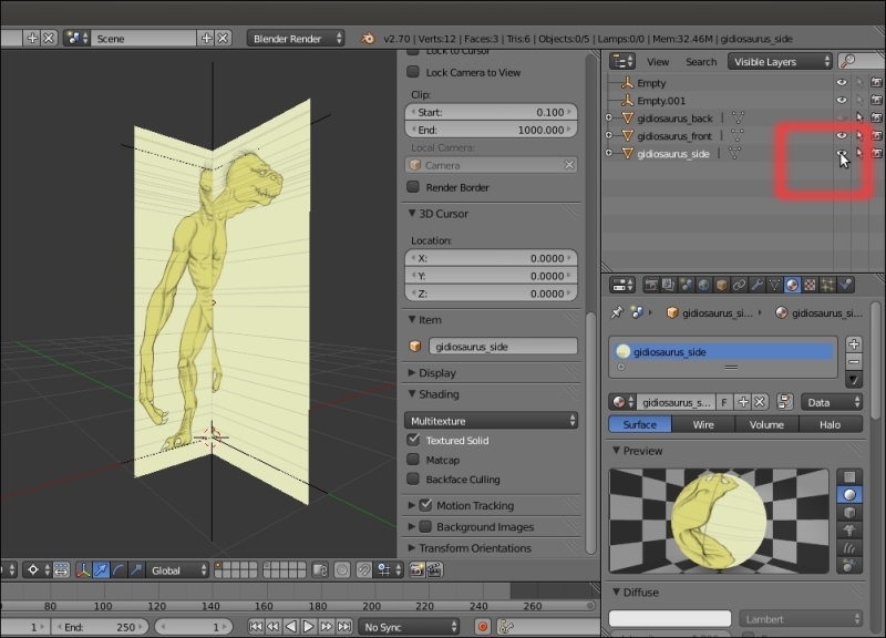
The imported Planes can be placed on different layers for practicality; they can also be on a single layer and their visibility can be toggled on and off by clicking on the eye icon in the Outliner.
Getting ready
The first thing to do is to be sure that all the required add-ons are enabled in the preferences; in this first recipe, we need the Images as Planes and Copy Attributes Menu add-ons. When starting Blender with the factory settings, they appear gray in the User Preferences panel's Add-ons list, meaning that they are not enabled yet. So, we'll do the following:
- Call the User Preferences panel (Ctrl + Alt + U) and go to the Add-ons tab.
- Under the Categories item on the left-hand side of the panel, click on 3D View.
- Check the empty little checkbox on the right-hand side of the 3D View: Copy Attributes Menu add-on to enable it.
- Go back to the Categories item on the left-hand side of the panel and click on Import-Export.
- Scroll down the add-ons list to the right-hand side to find the Import-Export: Import Images as Planes add-on (usually, towards the middle of the long list).
- Enable it, and then click on the Save User Settings button to the left-bottom of the panel and close it.
The User Preferences panel with the Categories list and the Addons tab to enable the several add-ons
There are still a few things we should do to prepare the 3D scene and make our life easier:
- Delete the already selected Cube primitive.
- Select the Lamp and the Camera and move them on to a different layer; I usually have them on the sixth layer (M key), in order to keep free and empty both the first and second rows of the left layer's block.
- The Outliner can be found in the top-right corner of the default workspace. It shows a list view of the scene. Set Display Mode of the Outliner to Visible Layers.
- Lastly, save the file as
Gidiosaurus_base_mesh.blend.
Although not strictly necessary, it would be better to have the three (at least in the case of a biped character, the Front, Side, and Back view) templates as separated images. This will allow us to load a specific one for each view, if necessary. Also, to facilitate the process, all these images should be the same height in pixels.
In our case, the required three views are provided for you in the files that accompany this book. You will find them in the templates folder. The Import Images as Planes add-on will take care of loading them into the scene:
- Left-click on File | Import | Images as Planes in the top-left menu on the main header of the Blender UI.
- On the page that just opened, go to the Material Settings column on the left-hand side (under the Import Images as Planes options) and enable the Shadeless item. Then, browse to the location where you placed your
templatesfolder and load thegidiosaurus_front.pngimage:The Import pop-up menu and the material settings subpanel of the Import Images as Planes add-on
- Rotate 90 degrees on the x axis (R | X | 90 | Enter) of the Plane that just appeared at the center of the scene (at the 3D Cursor location, actually; to reset the position of the 3D Cursor at the center of the scene, press the Shift + C keys).
- Press N to call the Properties sidepanel on the right-hand side of the active 3D window, and then go to the Shading subpanel and enable the Textured Solid item.
- Press 1 on the numpad to go to the Front view:
The imported plane with the relative UV-mapped image
Now, we know that our Gidiosaurus is a 2.5 meters tall beast. So, assuming that 1 Blender Unit is equal to 1 meter, we must scale the plane to make the character's front template two and a half Blender Units tall (Note that it is not the plane that must be 2.5 units tall, it's the character's shape inside the plane).
- Add an Empty to the scene (Shift + A | Empty | Plain Axes).
- Duplicate it and move it 2.5 units up on the z axis (Shift + D | Z | 2.5 | Enter).
- Go to the Outliner and click on the arrows on the side of the names of the two Empties (Empty and Empty.001), in order to make them gray and the Empties not selectable.
- Select the Plane and move it to align the bottom (feet) guideline to the horizontal arm of the first Empty (you actually have to move it on the z axis by 0.4470, but note that by pressing the Ctrl key, you can restrict movements to the grid and with Ctrl + Shift, you can have even finer control).
- Be sure that the 3D Cursor is at the object origin, and press the period key to switch Pivot center for rotation/scaling to the 3D Cursor.
- Press S to scale the Plane bigger and align the top-head guideline to the horizontal arm of the second Empty (you have to scale it to a value of 2.8300):
The properly scaled plane in the 3D scene
- Left-click again on File | Import | Images as Planes in the top-left menu on the main header of the Blender UI.
- Browse to the location where you placed your
templatesfolder and this time load thegidiosaurus_side.pngimage. - Shift + right-click on the first Plane (
gidiosaurus_front.png) to select it and make it the active one. Then, press Ctrl + C and from the Copy Attributes pop-up menu, select Copy Location. - Press Ctrl + C again and this time select Copy Rotation; press Ctrl + C one more time and select Copy Scale.
- Right-click to select the second Plane (
gidiosaurus_side.png) in the 3D view, or click on its name in the Outliner, and rotate it 90 degrees on the z axis (R | Z | 90 | Enter). - Optionally, you can move the second Plane to the second layer (M | second button on the Move to Layer panel).
- Again, left-click on File | Import | Images as Planes, browse to the
templatesfolder, and load thegidiosaurus_back.pngimage. - Repeat from step 12 to step 15 and move the third Plane on a different layer.
- Save the file.
We used a Python script, which is an add-on, to import planes into our scene that are automatically UV-mapped with the selected image, and inherit the images' height/width aspect ratio.
To have the textures/templates clearly visible from any angle in the 3D view, we have enabled the Shadeless option for the Planes materials; we did this directly in the importer preferences. We can also set each material to shadeless later in the Material window.
We then used another add-on to copy the attributes from a selected object, in order to quickly match common parameters such as location, scale, and rotation:
The template planes aligned to the x and y axis (Front and Side views)
The imported Planes can be placed on different layers for practicality; they can also be on a single layer and their visibility can be toggled on and off by clicking on the eye icon in the Outliner.
How to do it…
Although not strictly necessary, it would be better to have the three (at least in the case of a biped character, the Front, Side, and Back view) templates as separated images. This will allow us to load a specific one for each view, if necessary. Also, to facilitate the process, all these images should be the same height in pixels.
In our case, the required three views are provided for you in the files that accompany this book. You will find them in the templates folder. The Import Images as Planes add-on will take care of loading them into the scene:
- Left-click on File | Import | Images as Planes in the top-left menu on the main header of the Blender UI.
- On the page that just opened, go to the Material Settings column on the left-hand side (under the Import Images as Planes options) and enable the Shadeless item. Then, browse to the location where you placed your
templatesfolder and load thegidiosaurus_front.pngimage:The Import pop-up menu and the material settings subpanel of the Import Images as Planes add-on
- Rotate 90 degrees on the x axis (R | X | 90 | Enter) of the Plane that just appeared at the center of the scene (at the 3D Cursor location, actually; to reset the position of the 3D Cursor at the center of the scene, press the Shift + C keys).
- Press N to call the Properties sidepanel on the right-hand side of the active 3D window, and then go to the Shading subpanel and enable the Textured Solid item.
- Press 1 on the numpad to go to the Front view:
The imported plane with the relative UV-mapped image
Now, we know that our Gidiosaurus is a 2.5 meters tall beast. So, assuming that 1 Blender Unit is equal to 1 meter, we must scale the plane to make the character's front template two and a half Blender Units tall (Note that it is not the plane that must be 2.5 units tall, it's the character's shape inside the plane).
- Add an Empty to the scene (Shift + A | Empty | Plain Axes).
- Duplicate it and move it 2.5 units up on the z axis (Shift + D | Z | 2.5 | Enter).
- Go to the Outliner and click on the arrows on the side of the names of the two Empties (Empty and Empty.001), in order to make them gray and the Empties not selectable.
- Select the Plane and move it to align the bottom (feet) guideline to the horizontal arm of the first Empty (you actually have to move it on the z axis by 0.4470, but note that by pressing the Ctrl key, you can restrict movements to the grid and with Ctrl + Shift, you can have even finer control).
- Be sure that the 3D Cursor is at the object origin, and press the period key to switch Pivot center for rotation/scaling to the 3D Cursor.
- Press S to scale the Plane bigger and align the top-head guideline to the horizontal arm of the second Empty (you have to scale it to a value of 2.8300):
The properly scaled plane in the 3D scene
- Left-click again on File | Import | Images as Planes in the top-left menu on the main header of the Blender UI.
- Browse to the location where you placed your
templatesfolder and this time load thegidiosaurus_side.pngimage. - Shift + right-click on the first Plane (
gidiosaurus_front.png) to select it and make it the active one. Then, press Ctrl + C and from the Copy Attributes pop-up menu, select Copy Location. - Press Ctrl + C again and this time select Copy Rotation; press Ctrl + C one more time and select Copy Scale.
- Right-click to select the second Plane (
gidiosaurus_side.png) in the 3D view, or click on its name in the Outliner, and rotate it 90 degrees on the z axis (R | Z | 90 | Enter). - Optionally, you can move the second Plane to the second layer (M | second button on the Move to Layer panel).
- Again, left-click on File | Import | Images as Planes, browse to the
templatesfolder, and load thegidiosaurus_back.pngimage. - Repeat from step 12 to step 15 and move the third Plane on a different layer.
- Save the file.
We used a Python script, which is an add-on, to import planes into our scene that are automatically UV-mapped with the selected image, and inherit the images' height/width aspect ratio.
To have the textures/templates clearly visible from any angle in the 3D view, we have enabled the Shadeless option for the Planes materials; we did this directly in the importer preferences. We can also set each material to shadeless later in the Material window.
We then used another add-on to copy the attributes from a selected object, in order to quickly match common parameters such as location, scale, and rotation:
The template planes aligned to the x and y axis (Front and Side views)
The imported Planes can be placed on different layers for practicality; they can also be on a single layer and their visibility can be toggled on and off by clicking on the eye icon in the Outliner.
How it works…
We used a Python script, which is an add-on, to import planes into our scene that are automatically UV-mapped with the selected image, and inherit the images' height/width aspect ratio.
To have the textures/templates clearly visible from any angle in the 3D view, we have enabled the Shadeless option for the Planes materials; we did this directly in the importer preferences. We can also set each material to shadeless later in the Material window.
We then used another add-on to copy the attributes from a selected object, in order to quickly match common parameters such as location, scale, and rotation:
The template planes aligned to the x and y axis (Front and Side views)
The imported Planes can be placed on different layers for practicality; they can also be on a single layer and their visibility can be toggled on and off by clicking on the eye icon in the Outliner.
In this recipe, we'll set the character's templates by using Image Empties.
For this and the following recipes, there is no need for any particular preparations. Anyway, it is handy to prepare the two Empties to have markers in the 3D view for the 2.5 meters height of the character; so we'll do the following:
- Start a brand new Blender session and delete the already selected Cube primitive.
- Select the Lamp and Camera and move them on a different layer; I usually have them on the sixth layer, in order to keep free and empty both the first and second rows of the left layer's block.
- Add an Empty to the scene (Shift + A | Empty | Plain Axes).
- Duplicate it and move it 2.5 units up on the z axis (Shift + D | Z | 2.5 | Enter).
- Go to the Outliner and click on the arrows on the side of the names of the two Empties (Empty and Empty.001), in order to make them gray and the Empties not selectable.
- Save the file as
Gidiosaurus_base_mesh.blend.
So, now we are going to place the first Image Empty in the scene:
- Add an Empty to the scene (Shift + A | Empty | Image; it's the last item in the list).
- Go to the Object Data window in the main Properties panel on the right-hand side of the Blender UI; under the Empty subpanel, click on the Open button.
- Browse to the
templatesfolder and load thegidiosaurus_front.pngimage.
The Add pop-up menu and the Image Empty added to the 3D scene, with the settings to load and set the image
- Set the Offset X value to -0.50 and Offset Y to -0.05. Set the Size value to 2.830:

The Offset and Size settings
- Rotate the Empty 90 degrees on the x axis (R | X | 90 | Enter).
- Go to the Outliner and rename it
Empty_gidiosaurus_front. - Duplicate it (Shift + D), rotate it 90 degrees on the z axis, and in the Outliner, rename it as
Empty_gidiosaurus_side. - In the Empty subpanel under the Object Data window, click on the little icon (showing 3 users for that data block) on the right-hand side of the image name under Display, in order to make it a single user. Then, click on the little folder icon on the right-hand side of the image path to go inside the
templatesfolder again, and load thegidiosaurus_side.pngimage. - Reselect Empty_gidiosaurus_front and press Shift + D to duplicate it.
- Go to the Empty subpanel under the Object Data window, click on the little icon (showing 3 users for that datablock) on the right-hand side of the image name under Display, in order to make it a single user. Then, click on the little folder icon on the right-hand side of the image path to go inside the
templatesfolder again, and this time load thegidiosaurus_back.pngimage. - Go to the Outliner and rename it
Empty_gidiosaurus_back.
We have used one of the most underrated (well, in my opinion) tools in Blender: Empties, which can show images! Compared to the Images as Planes add-on, this has some advantages: these are not 3D geometry and the images are also visible in the 3D view without the Textured Solid option enabled (under Shading) and in Wireframe mode.
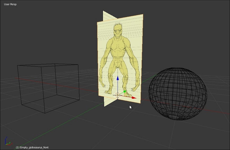
The Image Empties appear as textured also in Wireframe viewport shading mode
Exactly, as for the imported Planes of the former recipe, the visibility in the 3D view of the Image Empties can be toggled on and off by clicking on the eye icon in the Outliner.
Getting ready
For this and the following recipes, there is no need for any particular preparations. Anyway, it is handy to prepare the two Empties to have markers in the 3D view for the 2.5 meters height of the character; so we'll do the following:
- Start a brand new Blender session and delete the already selected Cube primitive.
- Select the Lamp and Camera and move them on a different layer; I usually have them on the sixth layer, in order to keep free and empty both the first and second rows of the left layer's block.
- Add an Empty to the scene (Shift + A | Empty | Plain Axes).
- Duplicate it and move it 2.5 units up on the z axis (Shift + D | Z | 2.5 | Enter).
- Go to the Outliner and click on the arrows on the side of the names of the two Empties (Empty and Empty.001), in order to make them gray and the Empties not selectable.
- Save the file as
Gidiosaurus_base_mesh.blend.
So, now we are going to place the first Image Empty in the scene:
- Add an Empty to the scene (Shift + A | Empty | Image; it's the last item in the list).
- Go to the Object Data window in the main Properties panel on the right-hand side of the Blender UI; under the Empty subpanel, click on the Open button.
- Browse to the
templatesfolder and load thegidiosaurus_front.pngimage.The Add pop-up menu and the Image Empty added to the 3D scene, with the settings to load and set the image
- Set the Offset X value to -0.50 and Offset Y to -0.05. Set the Size value to 2.830:
The Offset and Size settings
- Rotate the Empty 90 degrees on the x axis (R | X | 90 | Enter).
- Go to the Outliner and rename it
Empty_gidiosaurus_front. - Duplicate it (Shift + D), rotate it 90 degrees on the z axis, and in the Outliner, rename it as
Empty_gidiosaurus_side. - In the Empty subpanel under the Object Data window, click on the little icon (showing 3 users for that data block) on the right-hand side of the image name under Display, in order to make it a single user. Then, click on the little folder icon on the right-hand side of the image path to go inside the
templatesfolder again, and load thegidiosaurus_side.pngimage. - Reselect Empty_gidiosaurus_front and press Shift + D to duplicate it.
- Go to the Empty subpanel under the Object Data window, click on the little icon (showing 3 users for that datablock) on the right-hand side of the image name under Display, in order to make it a single user. Then, click on the little folder icon on the right-hand side of the image path to go inside the
templatesfolder again, and this time load thegidiosaurus_back.pngimage. - Go to the Outliner and rename it
Empty_gidiosaurus_back.
We have used one of the most underrated (well, in my opinion) tools in Blender: Empties, which can show images! Compared to the Images as Planes add-on, this has some advantages: these are not 3D geometry and the images are also visible in the 3D view without the Textured Solid option enabled (under Shading) and in Wireframe mode.
The Image Empties appear as textured also in Wireframe viewport shading mode
Exactly, as for the imported Planes of the former recipe, the visibility in the 3D view of the Image Empties can be toggled on and off by clicking on the eye icon in the Outliner.
How to do it…
So, now we are going to place the first Image Empty in the scene:
- Add an Empty to the scene (Shift + A | Empty | Image; it's the last item in the list).
- Go to the Object Data window in the main Properties panel on the right-hand side of the Blender UI; under the Empty subpanel, click on the Open button.
- Browse to the
templatesfolder and load thegidiosaurus_front.pngimage.The Add pop-up menu and the Image Empty added to the 3D scene, with the settings to load and set the image
- Set the Offset X value to -0.50 and Offset Y to -0.05. Set the Size value to 2.830:
The Offset and Size settings
- Rotate the Empty 90 degrees on the x axis (R | X | 90 | Enter).
- Go to the Outliner and rename it
Empty_gidiosaurus_front. - Duplicate it (Shift + D), rotate it 90 degrees on the z axis, and in the Outliner, rename it as
Empty_gidiosaurus_side. - In the Empty subpanel under the Object Data window, click on the little icon (showing 3 users for that data block) on the right-hand side of the image name under Display, in order to make it a single user. Then, click on the little folder icon on the right-hand side of the image path to go inside the
templatesfolder again, and load thegidiosaurus_side.pngimage. - Reselect Empty_gidiosaurus_front and press Shift + D to duplicate it.
- Go to the Empty subpanel under the Object Data window, click on the little icon (showing 3 users for that datablock) on the right-hand side of the image name under Display, in order to make it a single user. Then, click on the little folder icon on the right-hand side of the image path to go inside the
templatesfolder again, and this time load thegidiosaurus_back.pngimage. - Go to the Outliner and rename it
Empty_gidiosaurus_back.
We have used one of the most underrated (well, in my opinion) tools in Blender: Empties, which can show images! Compared to the Images as Planes add-on, this has some advantages: these are not 3D geometry and the images are also visible in the 3D view without the Textured Solid option enabled (under Shading) and in Wireframe mode.
The Image Empties appear as textured also in Wireframe viewport shading mode
Exactly, as for the imported Planes of the former recipe, the visibility in the 3D view of the Image Empties can be toggled on and off by clicking on the eye icon in the Outliner.
How it works…
We have used one of the most underrated (well, in my opinion) tools in Blender: Empties, which can show images! Compared to the Images as Planes add-on, this has some advantages: these are not 3D geometry and the images are also visible in the 3D view without the Textured Solid option enabled (under Shading) and in Wireframe mode.
The Image Empties appear as textured also in Wireframe viewport shading mode
Exactly, as for the imported Planes of the former recipe, the visibility in the 3D view of the Image Empties can be toggled on and off by clicking on the eye icon in the Outliner.
In this recipe, we'll set the character's templates by using the Background Images tool.
As in the former recipe, no need for any particular preparations; just carry out the preparatory steps as mentioned in the Getting ready section of the previous recipe.
So let's start by adding the templates as background images; that is, as reference images only visible in the background in Ortho view mode and, differently from the previous recipes, not as 3D objects actually present in the middle of the scene:
- Press 1 on the numpad to switch to the orthographic Front view and press Alt + Home to center the view on the 3D Cursor.
- If not already present, press N to bring up the Properties sidepanel to the right-hand side of the 3D window; scroll down to reach the Background Images subpanel and enable it with the checkbox. Then click on the little arrow to expand it.
- Click on the Add Image button; in the new option panel that appears, click on the Open button and browse to the
templatesfolder to load thegidiosaurus_front.pngimage. - Click on the little window to the side of the Axis item and switch from All Views to Front, and then set the Opacity slider to 1.000.
- Increase the Y offset value to make the bottom/feet guideline of the reference image aligned to the horizontal arm of the first Empty (you have to set it to 0.780).
- Scale Size smaller, using both the Empties that we set as references for the 2.5 meters height of the creature (you actually have to set the Scale value to 0.875).

The background image scaled and positioned through the settings in the N sidepanel
- Click on the little white arrow on the top-left side of the
gidiosaurus_front.pngsubwindow to collapse it. - Click on the Add Image button again; then, in the new option panel, click on the Open button, browse to the
templatesfolder, and load thegidiosaurus_side.pngimage. Then, set the Axis item to Right, Opacity to 1.000, Scale to 0.875, and Y to 0.780. - Repeat the operation for the
gidiosaurus_back.pngimage, set Axis to Back, and so on.
Press 3 on the numpad to switch to the Side view, 1 to switch to the Front view, and Ctrl + 1 to switch to the Back view, but remember that you must be in the Ortho mode (5 key on the numpad) to see the background templates:

The N sidepanel settings to assign the background image to a view
Getting ready
As in the former recipe, no need for any particular preparations; just carry out the preparatory steps as mentioned in the Getting ready section of the previous recipe.
So let's start by adding the templates as background images; that is, as reference images only visible in the background in Ortho view mode and, differently from the previous recipes, not as 3D objects actually present in the middle of the scene:
- Press 1 on the numpad to switch to the orthographic Front view and press Alt + Home to center the view on the 3D Cursor.
- If not already present, press N to bring up the Properties sidepanel to the right-hand side of the 3D window; scroll down to reach the Background Images subpanel and enable it with the checkbox. Then click on the little arrow to expand it.
- Click on the Add Image button; in the new option panel that appears, click on the Open button and browse to the
templatesfolder to load thegidiosaurus_front.pngimage. - Click on the little window to the side of the Axis item and switch from All Views to Front, and then set the Opacity slider to 1.000.
- Increase the Y offset value to make the bottom/feet guideline of the reference image aligned to the horizontal arm of the first Empty (you have to set it to 0.780).
- Scale Size smaller, using both the Empties that we set as references for the 2.5 meters height of the creature (you actually have to set the Scale value to 0.875).
The background image scaled and positioned through the settings in the N sidepanel
- Click on the little white arrow on the top-left side of the
gidiosaurus_front.pngsubwindow to collapse it. - Click on the Add Image button again; then, in the new option panel, click on the Open button, browse to the
templatesfolder, and load thegidiosaurus_side.pngimage. Then, set the Axis item to Right, Opacity to 1.000, Scale to 0.875, and Y to 0.780. - Repeat the operation for the
gidiosaurus_back.pngimage, set Axis to Back, and so on.
Press 3 on the numpad to switch to the Side view, 1 to switch to the Front view, and Ctrl + 1 to switch to the Back view, but remember that you must be in the Ortho mode (5 key on the numpad) to see the background templates:
The N sidepanel settings to assign the background image to a view
How to do it…
So let's start by adding the templates as background images; that is, as reference images only visible in the background in Ortho view mode and, differently from the previous recipes, not as 3D objects actually present in the middle of the scene:
- Press 1 on the numpad to switch to the orthographic Front view and press Alt + Home to center the view on the 3D Cursor.
- If not already present, press N to bring up the Properties sidepanel to the right-hand side of the 3D window; scroll down to reach the Background Images subpanel and enable it with the checkbox. Then click on the little arrow to expand it.
- Click on the Add Image button; in the new option panel that appears, click on the Open button and browse to the
templatesfolder to load thegidiosaurus_front.pngimage. - Click on the little window to the side of the Axis item and switch from All Views to Front, and then set the Opacity slider to 1.000.
- Increase the Y offset value to make the bottom/feet guideline of the reference image aligned to the horizontal arm of the first Empty (you have to set it to 0.780).
- Scale Size smaller, using both the Empties that we set as references for the 2.5 meters height of the creature (you actually have to set the Scale value to 0.875).
The background image scaled and positioned through the settings in the N sidepanel
- Click on the little white arrow on the top-left side of the
gidiosaurus_front.pngsubwindow to collapse it. - Click on the Add Image button again; then, in the new option panel, click on the Open button, browse to the
templatesfolder, and load thegidiosaurus_side.pngimage. Then, set the Axis item to Right, Opacity to 1.000, Scale to 0.875, and Y to 0.780. - Repeat the operation for the
gidiosaurus_back.pngimage, set Axis to Back, and so on.
Press 3 on the numpad to switch to the Side view, 1 to switch to the Front view, and Ctrl + 1 to switch to the Back view, but remember that you must be in the Ortho mode (5 key on the numpad) to see the background templates:
The N sidepanel settings to assign the background image to a view
In the previous recipes, we saw three different ways to set up the template images; just remember that one method doesn't exclude the others, so in my opinion, the best setup you can have is: Image Empties on one layer (visibility toggled using the eye icons in the Outliner) together with Background Images. This way you can not only have templates visible in the three orthographic views, but also in the perspective view (and this can sometimes be really handy).
However, whatever the method you choose, now it's time to start to build the character's base mesh. To do this, we are going to use the Skin modifier.
First, let's prepare the scene:
- In case it's needed, reopen the
Gidiosaurus_base_mesh.blendfile. - Click on an empty scene layer to activate it; for example, the 11th.

The starting empty scene and the scene layer's buttons on the 3D window toolbar
- Be sure that the 3D Cursor is at the center of the scene (Shift + C).
- Add a Plane (press Shift + A and go to Mesh | Plane). If you are working with the Factory Settings, you must now press Tab to go in to Edit Mode, and then Shift + right-click to deselect just one vertex.
- Press X and delete the three vertices that are still selected.
- Right-click to select the remaining vertex and put it at the cursor location in the center of the scene (Shift + S, and then select Selection to Cursor).
- Go to the Object Modifiers window on the main Properties panel, to the right-hand side, and assign a Skin modifier; a cube appears around the vertex. Uncheck X under Symmetry Axes in the modifier's panel:

The cube geometry created by just one vertex and the Skin modifier
- Assign a Mirror modifier and check Clipping.
- Assign a Subdivision Surface modifier and check Optimal Display.
- Go to the toolbar of the 3D view to click on the Limit selection to visible icon and disable it; the icon appears only in Edit Mode and in all the viewport shading modes, except for Wireframe and Bounding Box, and has the appearance of a cube with the vertices selected:

The “Limit selection to visible” button on the 3D viewport toolbar and the cube geometry subdivided through the Subdivision Surface modifier
- Press 3 on the numpad to go in the Side view:

The created geometry and the side-view template reference
We are now going to move and extrude the vertex according to our template images, working as guides, and therefore generating a 3D geometry (thanks to the Skin modifier):
- Press G and move the vertex to the pelvis area. Then, press Ctrl + A and move the mouse cursor towards the vertex to lower the weight/influence of the vertex itself on the generated mesh; scaling it smaller to fit the hip size showing on the template:

Moving the geometry to the character's pelvis area
- Press E and extrude the vertex by moving it up on the z axis; place it at the bottom of the rib cage.
- Go on extruding the vertex by following the lateral shape of the character in the template. Don't be worried about the volumes; for the moment, just build a stick-figure going up the torso:

Extruding the vertices to create a new geometry
- Proceed to the neck and stop at the attachment of the head location.
- Select the last two vertices you extruded; press Ctrl + A and move the mouse cursor towards them to scale down their influence in order to provide a slim-looking neck:

Scaling down the influence of the vertices
- Press 1 on the numpad to switch to the Front view, and then select the bottom vertex and extrude it down to cover the base of the creature's pelvis. Press Ctrl + A | X to scale it only on the x axis:

Adjusting the weight of the vertices in the Front view
- Go to the Mirror modifier and uncheck the Clipping item.
- Select the middle thorax vertex and extrude it to the right-hand side to build the shoulder. Press Ctrl + A to scale it smaller:

Creating the shoulders
- Extrude the shoulder vertex, following the arm shape, and stop at the wrist; select the just-extruded arms' vertices and use Ctrl + A to scale them smaller.
- Reselect the shoulder vertex, and use Shift + V to slide it along the shoulder's edge in order to adjust the location and fix the area shape:

Creating the arms
- Select the middle thorax vertex we extruded the shoulder from and go to the Skin modifier; click on the Mark Loose button:

Making a more natural transition from the thorax to the arms
- Select the second vertex from the bottom and extrude it to the right-hand side to build the hip, and then extrude again and stop at the knee. Use Ctrl + A on the vertex to make it smaller:

Extruding the thighs
- Go on extruding the vertex to build the leg. Then, select the wrist vertex and extrude it to build the hand:

Extruding to complete the leg
- Press 3 to go to the Side view.
- Individually, select the vertices of the knee, ankle, and foot, and move them to be aligned with the character's posture (you can use the widget for this and, if needed, you can press Z to go in to Wireframe viewport shading mode); do the same with the vertices of the arm:

Adjusting the arm's position
- Select the vertices of the shoulder and elbow, and move them forward according to the template position; do the same with the vertices of the neck and waist:

Adjusting the position of the shoulders, thorax, and neck
- Select the vertex connecting the shoulder to the thorax and use Shift + V to slide it upwards, in order to make room for more vertices in the chest area. Use Shift to select the vertex at the bottom of the rib cage and press W; in the Specials pop-up menu, select Subdivide and, right after the subdivision, in the option panel at the bottom-left of the Blender UI, set Number of Cuts to 2:

Subdividing an edge
- In the Side view, select the upper one of the new vertices and use Ctrl + A to scale it bigger. Adjust the position and scale of the vertices around that area (neck and shoulder) to obtain, as much as possible, a shape that is more regular and similar to the template. However, don't worry too much about a perfect correspondence, it can be adjusted later:

Refining the shoulder's shape
- Extrude the bulk of the head. Select the last hand vertex and scale it smaller. Then, select the upper hand vertex and extrude two more fingers (scale their influence smaller and adjust their position to obtain a more regular and ordinate flow of the polygons in the generated geometry):

Creating the head, hands, and fingers
- As always, following the templates as reference, extrude again to complete the fingers; use all the templates to check the accuracy of the proportions and positions, and the Front, Side, and Back views too:

Adjusting the position of the fingers according to the templates
- Do the same thing for the foot, and we are almost done with the major part of the mesh:

Creating the feet toes
Now, it's only a matter of refining, as much as possible, the mesh's parts to resemble best the final shape of the character. Let's try with the arm first:
- Select the two extreme vertices of the forearm and press W | Subdivide | 2 (in the bottom Tool panel) to add 2 vertices in the middle. Then, use Ctrl + A to scale and move them outward to curve the forearm a little bit. Do the same for the thigh by slightly moving the vertices outward and backward:

Refining the shape of arms and legs
- Repeat the same procedure with the upper arm, shin, foot, and fingers; any part where it's possible, but don't go crazy about it. The goal of such a technique is just to quickly obtain a mesh that is good enough to be used as a starting point for the sculpting, and not an already finished model:

The completed base mesh
- Press Tab to go out of the Edit Mode; go to the Outliner and rename the base mesh as
Gidiosaurus. Then, save the file.
The Skin modifier is a quick and simple way to build almost any shape; its use is very simple: first, you extrude vertices (actually, it would be enough to add vertices; it's not mandatory to extrude them, but certainly it's more handy than using Ctrl + left-click to add them at several locations), and then using the Ctrl + A shortcut, you scale smaller or bigger the influence that these vertices have on the 3D geometry generated on the fly.
If you have already tried it, you must have seen that the more the complexity of the mesh grows, the more the generated geometry starts to become a little unstable, often resulting in intersecting and overlapping faces. Sometimes this seems unavoidable, but in any case it is not a big issue and can be easily fixed through a little bit of editing. We'll see this in the next chapter.
Getting ready
First, let's prepare the scene:
- In case it's needed, reopen the
Gidiosaurus_base_mesh.blendfile. - Click on an empty scene layer to activate it; for example, the 11th.
The starting empty scene and the scene layer's buttons on the 3D window toolbar
- Be sure that the 3D Cursor is at the center of the scene (Shift + C).
- Add a Plane (press Shift + A and go to Mesh | Plane). If you are working with the Factory Settings, you must now press Tab to go in to Edit Mode, and then Shift + right-click to deselect just one vertex.
- Press X and delete the three vertices that are still selected.
- Right-click to select the remaining vertex and put it at the cursor location in the center of the scene (Shift + S, and then select Selection to Cursor).
- Go to the Object Modifiers window on the main Properties panel, to the right-hand side, and assign a Skin modifier; a cube appears around the vertex. Uncheck X under Symmetry Axes in the modifier's panel:
The cube geometry created by just one vertex and the Skin modifier
- Assign a Mirror modifier and check Clipping.
- Assign a Subdivision Surface modifier and check Optimal Display.
- Go to the toolbar of the 3D view to click on the Limit selection to visible icon and disable it; the icon appears only in Edit Mode and in all the viewport shading modes, except for Wireframe and Bounding Box, and has the appearance of a cube with the vertices selected:
The “Limit selection to visible” button on the 3D viewport toolbar and the cube geometry subdivided through the Subdivision Surface modifier
- Press 3 on the numpad to go in the Side view:
The created geometry and the side-view template reference
We are now going to move and extrude the vertex according to our template images, working as guides, and therefore generating a 3D geometry (thanks to the Skin modifier):
- Press G and move the vertex to the pelvis area. Then, press Ctrl + A and move the mouse cursor towards the vertex to lower the weight/influence of the vertex itself on the generated mesh; scaling it smaller to fit the hip size showing on the template:
Moving the geometry to the character's pelvis area
- Press E and extrude the vertex by moving it up on the z axis; place it at the bottom of the rib cage.
- Go on extruding the vertex by following the lateral shape of the character in the template. Don't be worried about the volumes; for the moment, just build a stick-figure going up the torso:
Extruding the vertices to create a new geometry
- Proceed to the neck and stop at the attachment of the head location.
- Select the last two vertices you extruded; press Ctrl + A and move the mouse cursor towards them to scale down their influence in order to provide a slim-looking neck:
Scaling down the influence of the vertices
- Press 1 on the numpad to switch to the Front view, and then select the bottom vertex and extrude it down to cover the base of the creature's pelvis. Press Ctrl + A | X to scale it only on the x axis:
Adjusting the weight of the vertices in the Front view
- Go to the Mirror modifier and uncheck the Clipping item.
- Select the middle thorax vertex and extrude it to the right-hand side to build the shoulder. Press Ctrl + A to scale it smaller:
Creating the shoulders
- Extrude the shoulder vertex, following the arm shape, and stop at the wrist; select the just-extruded arms' vertices and use Ctrl + A to scale them smaller.
- Reselect the shoulder vertex, and use Shift + V to slide it along the shoulder's edge in order to adjust the location and fix the area shape:
Creating the arms
- Select the middle thorax vertex we extruded the shoulder from and go to the Skin modifier; click on the Mark Loose button:
Making a more natural transition from the thorax to the arms
- Select the second vertex from the bottom and extrude it to the right-hand side to build the hip, and then extrude again and stop at the knee. Use Ctrl + A on the vertex to make it smaller:
Extruding the thighs
- Go on extruding the vertex to build the leg. Then, select the wrist vertex and extrude it to build the hand:
Extruding to complete the leg
- Press 3 to go to the Side view.
- Individually, select the vertices of the knee, ankle, and foot, and move them to be aligned with the character's posture (you can use the widget for this and, if needed, you can press Z to go in to Wireframe viewport shading mode); do the same with the vertices of the arm:
Adjusting the arm's position
- Select the vertices of the shoulder and elbow, and move them forward according to the template position; do the same with the vertices of the neck and waist:
Adjusting the position of the shoulders, thorax, and neck
- Select the vertex connecting the shoulder to the thorax and use Shift + V to slide it upwards, in order to make room for more vertices in the chest area. Use Shift to select the vertex at the bottom of the rib cage and press W; in the Specials pop-up menu, select Subdivide and, right after the subdivision, in the option panel at the bottom-left of the Blender UI, set Number of Cuts to 2:
Subdividing an edge
- In the Side view, select the upper one of the new vertices and use Ctrl + A to scale it bigger. Adjust the position and scale of the vertices around that area (neck and shoulder) to obtain, as much as possible, a shape that is more regular and similar to the template. However, don't worry too much about a perfect correspondence, it can be adjusted later:
Refining the shoulder's shape
- Extrude the bulk of the head. Select the last hand vertex and scale it smaller. Then, select the upper hand vertex and extrude two more fingers (scale their influence smaller and adjust their position to obtain a more regular and ordinate flow of the polygons in the generated geometry):
Creating the head, hands, and fingers
- As always, following the templates as reference, extrude again to complete the fingers; use all the templates to check the accuracy of the proportions and positions, and the Front, Side, and Back views too:
Adjusting the position of the fingers according to the templates
- Do the same thing for the foot, and we are almost done with the major part of the mesh:
Creating the feet toes
Now, it's only a matter of refining, as much as possible, the mesh's parts to resemble best the final shape of the character. Let's try with the arm first:
- Select the two extreme vertices of the forearm and press W | Subdivide | 2 (in the bottom Tool panel) to add 2 vertices in the middle. Then, use Ctrl + A to scale and move them outward to curve the forearm a little bit. Do the same for the thigh by slightly moving the vertices outward and backward:
Refining the shape of arms and legs
- Repeat the same procedure with the upper arm, shin, foot, and fingers; any part where it's possible, but don't go crazy about it. The goal of such a technique is just to quickly obtain a mesh that is good enough to be used as a starting point for the sculpting, and not an already finished model:
The completed base mesh
- Press Tab to go out of the Edit Mode; go to the Outliner and rename the base mesh as
Gidiosaurus. Then, save the file.
The Skin modifier is a quick and simple way to build almost any shape; its use is very simple: first, you extrude vertices (actually, it would be enough to add vertices; it's not mandatory to extrude them, but certainly it's more handy than using Ctrl + left-click to add them at several locations), and then using the Ctrl + A shortcut, you scale smaller or bigger the influence that these vertices have on the 3D geometry generated on the fly.
If you have already tried it, you must have seen that the more the complexity of the mesh grows, the more the generated geometry starts to become a little unstable, often resulting in intersecting and overlapping faces. Sometimes this seems unavoidable, but in any case it is not a big issue and can be easily fixed through a little bit of editing. We'll see this in the next chapter.
How to do it…
We are now going to move and extrude the vertex according to our template images, working as guides, and therefore generating a 3D geometry (thanks to the Skin modifier):
- Press G and move the vertex to the pelvis area. Then, press Ctrl + A and move the mouse cursor towards the vertex to lower the weight/influence of the vertex itself on the generated mesh; scaling it smaller to fit the hip size showing on the template:
Moving the geometry to the character's pelvis area
- Press E and extrude the vertex by moving it up on the z axis; place it at the bottom of the rib cage.
- Go on extruding the vertex by following the lateral shape of the character in the template. Don't be worried about the volumes; for the moment, just build a stick-figure going up the torso:
Extruding the vertices to create a new geometry
- Proceed to the neck and stop at the attachment of the head location.
- Select the last two vertices you extruded; press Ctrl + A and move the mouse cursor towards them to scale down their influence in order to provide a slim-looking neck:
Scaling down the influence of the vertices
- Press 1 on the numpad to switch to the Front view, and then select the bottom vertex and extrude it down to cover the base of the creature's pelvis. Press Ctrl + A | X to scale it only on the x axis:
Adjusting the weight of the vertices in the Front view
- Go to the Mirror modifier and uncheck the Clipping item.
- Select the middle thorax vertex and extrude it to the right-hand side to build the shoulder. Press Ctrl + A to scale it smaller:
Creating the shoulders
- Extrude the shoulder vertex, following the arm shape, and stop at the wrist; select the just-extruded arms' vertices and use Ctrl + A to scale them smaller.
- Reselect the shoulder vertex, and use Shift + V to slide it along the shoulder's edge in order to adjust the location and fix the area shape:
Creating the arms
- Select the middle thorax vertex we extruded the shoulder from and go to the Skin modifier; click on the Mark Loose button:
Making a more natural transition from the thorax to the arms
- Select the second vertex from the bottom and extrude it to the right-hand side to build the hip, and then extrude again and stop at the knee. Use Ctrl + A on the vertex to make it smaller:
Extruding the thighs
- Go on extruding the vertex to build the leg. Then, select the wrist vertex and extrude it to build the hand:
Extruding to complete the leg
- Press 3 to go to the Side view.
- Individually, select the vertices of the knee, ankle, and foot, and move them to be aligned with the character's posture (you can use the widget for this and, if needed, you can press Z to go in to Wireframe viewport shading mode); do the same with the vertices of the arm:
Adjusting the arm's position
- Select the vertices of the shoulder and elbow, and move them forward according to the template position; do the same with the vertices of the neck and waist:
Adjusting the position of the shoulders, thorax, and neck
- Select the vertex connecting the shoulder to the thorax and use Shift + V to slide it upwards, in order to make room for more vertices in the chest area. Use Shift to select the vertex at the bottom of the rib cage and press W; in the Specials pop-up menu, select Subdivide and, right after the subdivision, in the option panel at the bottom-left of the Blender UI, set Number of Cuts to 2:
Subdividing an edge
- In the Side view, select the upper one of the new vertices and use Ctrl + A to scale it bigger. Adjust the position and scale of the vertices around that area (neck and shoulder) to obtain, as much as possible, a shape that is more regular and similar to the template. However, don't worry too much about a perfect correspondence, it can be adjusted later:
Refining the shoulder's shape
- Extrude the bulk of the head. Select the last hand vertex and scale it smaller. Then, select the upper hand vertex and extrude two more fingers (scale their influence smaller and adjust their position to obtain a more regular and ordinate flow of the polygons in the generated geometry):
Creating the head, hands, and fingers
- As always, following the templates as reference, extrude again to complete the fingers; use all the templates to check the accuracy of the proportions and positions, and the Front, Side, and Back views too:
Adjusting the position of the fingers according to the templates
- Do the same thing for the foot, and we are almost done with the major part of the mesh:
Creating the feet toes
Now, it's only a matter of refining, as much as possible, the mesh's parts to resemble best the final shape of the character. Let's try with the arm first:
- Select the two extreme vertices of the forearm and press W | Subdivide | 2 (in the bottom Tool panel) to add 2 vertices in the middle. Then, use Ctrl + A to scale and move them outward to curve the forearm a little bit. Do the same for the thigh by slightly moving the vertices outward and backward:
Refining the shape of arms and legs
- Repeat the same procedure with the upper arm, shin, foot, and fingers; any part where it's possible, but don't go crazy about it. The goal of such a technique is just to quickly obtain a mesh that is good enough to be used as a starting point for the sculpting, and not an already finished model:
The completed base mesh
- Press Tab to go out of the Edit Mode; go to the Outliner and rename the base mesh as
Gidiosaurus. Then, save the file.
The Skin modifier is a quick and simple way to build almost any shape; its use is very simple: first, you extrude vertices (actually, it would be enough to add vertices; it's not mandatory to extrude them, but certainly it's more handy than using Ctrl + left-click to add them at several locations), and then using the Ctrl + A shortcut, you scale smaller or bigger the influence that these vertices have on the 3D geometry generated on the fly.
If you have already tried it, you must have seen that the more the complexity of the mesh grows, the more the generated geometry starts to become a little unstable, often resulting in intersecting and overlapping faces. Sometimes this seems unavoidable, but in any case it is not a big issue and can be easily fixed through a little bit of editing. We'll see this in the next chapter.
How it works…
The Skin modifier is a quick and simple way to build almost any shape; its use is very simple: first, you extrude vertices (actually, it would be enough to add vertices; it's not mandatory to extrude them, but certainly it's more handy than using Ctrl + left-click to add them at several locations), and then using the Ctrl + A shortcut, you scale smaller or bigger the influence that these vertices have on the 3D geometry generated on the fly.
If you have already tried it, you must have seen that the more the complexity of the mesh grows, the more the generated geometry starts to become a little unstable, often resulting in intersecting and overlapping faces. Sometimes this seems unavoidable, but in any case it is not a big issue and can be easily fixed through a little bit of editing. We'll see this in the next chapter.
In this chapter, we will cover the following recipes:
- Using the Skin modifier's Armature option
- Editing the mesh
- Preparing the base mesh for sculpting
- Using the Multiresolution modifier and the Dynamic topology feature
- Sculpting the character's base mesh
In the previous chapter, we built the base mesh by using the Skin modifier and on the base of the reference templates; in this chapter, we are going to prepare this basic mesh for the sculpting, by editing it and cleaning up any mistakes the Skin modifier may have made (usually, overlapping and triangular faces, missing edge loops, and so on).
The Skin modifier has an option to create an Armature on the fly to pose the generated mesh. This Armature can just be useful in cases where you want to modify the position of a part of the generated mesh.
Note that using the generated Armature to pose the base mesh, in our case, is not necessary, and therefore this recipe is treated here only as an example and it won't affect the following recipes in the chapter.
So, let's suppose that we want the arms to be posed more horizontally and widely spread:
- If this is the case, reopen the
Gidiosaurus_base_mesh.blendfile and save it with a different name (something likeGidiosaurus_Skin_Armature.blend). - Select the Gidiosaurus mesh and press Tab to go into Edit Mode; then, select the central pelvis vertex.
- Go to the Object Modifiers window under the main Properties panel to the right-hand side of the screen and then to the Skin modifier subpanel; click on the Mark Root button:

The root vertex
- Press Tab again to exit Edit Mode.
Creating the rig (that is the skeleton Armature made by bones and used to deform, and therefore, animate a mesh) for our character's base mesh is really simple:
- Again, in the Skin modifier subpanel, click on the Create Armature button. The Armature is created instantly and an Armature modifier is automatically assigned to the mesh; in the modifier stack, move it to the top so that it is above the Mirror modifier and our posed half-mesh will be correctly mirrored:

The Armature created by the Skin modifier
- Press Ctrl + Tab to enter Pose Mode for the already selected Armature and then select the upper bone of the arm.
- In the toolbar of the 3D viewport, find the widget manipulators panel, click on the rotation Transformation manipulators (the third icon from the left), and set Transform Orientation to Normal.
- By using the rotate widget, rotate the selected bone and consequently the arm (be careful that, as already mentioned, the newly created Armature modifier is at the top of the modifier stack, otherwise the rotation will not correctly deform the mirrored mesh):

Rotating the arms through the Armature
- Exit Pose Mode and reselect the Gidiosaurus mesh.
- Go to the Skin modifier subpanel under the Object Modifiers window; click on the Apply button to apply the modifier.
- Go to the Armature modifier and click on the Apply button to also apply the rig transformations.
- At this point, we can also select the Armature object and delete it (X key).
By clicking on the Create Armature button, the Skin modifier creates a bone for each edge connecting the extruded vertices, it adds an Armature modifier to the generated base mesh, and automatically assigns vertex groups to the base mesh and skins them with the corresponding bones.
The bones of this Armature work in Forward Kinematics, which means they are chained following the child/parent relation, with the first (parent) bone created at the Root location we had set at step 3 of the Getting ready section.
Note that the bones of the Armature can be used not only to rotate limbs, but also to scale bigger or smaller parts of the mesh, in order to further tweak the shape of the base mesh.
Getting ready
So, let's suppose that we want the arms to be posed more horizontally and widely spread:
- If this is the case, reopen the
Gidiosaurus_base_mesh.blendfile and save it with a different name (something likeGidiosaurus_Skin_Armature.blend). - Select the Gidiosaurus mesh and press Tab to go into Edit Mode; then, select the central pelvis vertex.
- Go to the Object Modifiers window under the main Properties panel to the right-hand side of the screen and then to the Skin modifier subpanel; click on the Mark Root button:
The root vertex
- Press Tab again to exit Edit Mode.
Creating the rig (that is the skeleton Armature made by bones and used to deform, and therefore, animate a mesh) for our character's base mesh is really simple:
- Again, in the Skin modifier subpanel, click on the Create Armature button. The Armature is created instantly and an Armature modifier is automatically assigned to the mesh; in the modifier stack, move it to the top so that it is above the Mirror modifier and our posed half-mesh will be correctly mirrored:
The Armature created by the Skin modifier
- Press Ctrl + Tab to enter Pose Mode for the already selected Armature and then select the upper bone of the arm.
- In the toolbar of the 3D viewport, find the widget manipulators panel, click on the rotation Transformation manipulators (the third icon from the left), and set Transform Orientation to Normal.
- By using the rotate widget, rotate the selected bone and consequently the arm (be careful that, as already mentioned, the newly created Armature modifier is at the top of the modifier stack, otherwise the rotation will not correctly deform the mirrored mesh):
Rotating the arms through the Armature
- Exit Pose Mode and reselect the Gidiosaurus mesh.
- Go to the Skin modifier subpanel under the Object Modifiers window; click on the Apply button to apply the modifier.
- Go to the Armature modifier and click on the Apply button to also apply the rig transformations.
- At this point, we can also select the Armature object and delete it (X key).
By clicking on the Create Armature button, the Skin modifier creates a bone for each edge connecting the extruded vertices, it adds an Armature modifier to the generated base mesh, and automatically assigns vertex groups to the base mesh and skins them with the corresponding bones.
The bones of this Armature work in Forward Kinematics, which means they are chained following the child/parent relation, with the first (parent) bone created at the Root location we had set at step 3 of the Getting ready section.
Note that the bones of the Armature can be used not only to rotate limbs, but also to scale bigger or smaller parts of the mesh, in order to further tweak the shape of the base mesh.
How to do it…
Creating the rig (that is the skeleton Armature made by bones and used to deform, and therefore, animate a mesh) for our character's base mesh is really simple:
- Again, in the Skin modifier subpanel, click on the Create Armature button. The Armature is created instantly and an Armature modifier is automatically assigned to the mesh; in the modifier stack, move it to the top so that it is above the Mirror modifier and our posed half-mesh will be correctly mirrored:
The Armature created by the Skin modifier
- Press Ctrl + Tab to enter Pose Mode for the already selected Armature and then select the upper bone of the arm.
- In the toolbar of the 3D viewport, find the widget manipulators panel, click on the rotation Transformation manipulators (the third icon from the left), and set Transform Orientation to Normal.
- By using the rotate widget, rotate the selected bone and consequently the arm (be careful that, as already mentioned, the newly created Armature modifier is at the top of the modifier stack, otherwise the rotation will not correctly deform the mirrored mesh):
Rotating the arms through the Armature
- Exit Pose Mode and reselect the Gidiosaurus mesh.
- Go to the Skin modifier subpanel under the Object Modifiers window; click on the Apply button to apply the modifier.
- Go to the Armature modifier and click on the Apply button to also apply the rig transformations.
- At this point, we can also select the Armature object and delete it (X key).
By clicking on the Create Armature button, the Skin modifier creates a bone for each edge connecting the extruded vertices, it adds an Armature modifier to the generated base mesh, and automatically assigns vertex groups to the base mesh and skins them with the corresponding bones.
The bones of this Armature work in Forward Kinematics, which means they are chained following the child/parent relation, with the first (parent) bone created at the Root location we had set at step 3 of the Getting ready section.
Note that the bones of the Armature can be used not only to rotate limbs, but also to scale bigger or smaller parts of the mesh, in order to further tweak the shape of the base mesh.
How it works…
By clicking on the Create Armature button, the Skin modifier creates a bone for each edge connecting the extruded vertices, it adds an Armature modifier to the generated base mesh, and automatically assigns vertex groups to the base mesh and skins them with the corresponding bones.
The bones of this Armature work in Forward Kinematics, which means they are chained following the child/parent relation, with the first (parent) bone created at the Root location we had set at step 3 of the Getting ready section.
Note that the bones of the Armature can be used not only to rotate limbs, but also to scale bigger or smaller parts of the mesh, in order to further tweak the shape of the base mesh.
There's more…
Note that the bones of the Armature can be used not only to rotate limbs, but also to scale bigger or smaller parts of the mesh, in order to further tweak the shape of the base mesh.
Once we have applied the Skin and Armature modifiers, we are left with an almost ready-to-use base mesh; what we need to do now is clean the possibly overlapping faces and whatever other mistakes were made by the Skin modifier.
Be careful not to be confused by the previous recipe, which was meant only as a possible example; we didn't actually use the Skin modifier's Armature to change the pose of the base mesh.
Let's prepare the mesh and the view:
- Go to the Object Modifiers window under the main Properties panel and then to the Mirror modifier subpanel and click on the little X icon to the right in order to delete the modifier; you are left with half of the mesh (actually the half that is really generated by the Skin modifier; the other side was simulated by the Mirror modifier):

Deleting the Mirror modifier
- Press Tab to go into Edit Mode, 7 on the numpad to go into Top view, and Z to go into the Wireframe viewport shading mode.
- Press Ctrl + R to add an edge-loop to the middle of the mesh; don't move the mouse, and left-click a second time to confirm that you want it at 0.0000 location:

Adding a central edge-loop
Sometimes, depending on the topology created by the Skin modifier, you may not be able to make a single clean loop cut by the Ctrl + R key shortcut. In this case, still in Edit Mode, you can press the K key to call the Knife Tool, left-click on the mesh to place the cuts, and press Enter to confirm (press Shift + K if you want only the newly created edge-loops selected after pressing Enter). This way, you can create several loop cuts, connect them together and, if necessary, move and/or scale them to the middle along the x axis.
In fact, you can do the following:
- Go out of Edit Mode and press Shift + S; in the Snap pop-up menu, select Cursor to Selected (to center the cursor at the middle of the mesh).
- Press the period (.) key to switch Pivot Point to 3D Cursor and then press Tab to go again into Edit Mode.
- With the middle edge-loop already selected, press S | X | 0 | Enter to scale all its vertices to the 3D Cursor position along the x axis and align them at the perfect center:

Scaling the central edge-loop vertices along the x axis
- Press A to deselect all the vertices and then press B and box-select the vertices on the left-hand side of the screen (actually the mesh's right-side vertices):

Box-selecting the left vertices
- Press X and, in the Delete pop-up menu, select the Vertices item to delete them:

Deleting the left vertices
- Go out of Edit Mode and, in the Object Modifiers window, assign a new Mirror modifier (check Clipping) to the mesh; move it before the Subdivision Surface modifier in the stack.
- If needed, this is the point where you can manually edit the mesh by converting triangle faces to quads (select two consecutive triangular faces and press Alt + J), creating, closing, or moving edge-loops (by using the Knife Tool, for example, around the arms and legs attachments to the body), and so on.
- Save the file as
Gidiosaurus_base_mesh.blend.
Well, in our case, everything went right with the Skin modifier, so there is no need for any big editing of the mesh! In effect, it was enough to delete the first Mirror modifier (that we actually used mostly for visual feedback) to get rid of all the overlapping faces and obtain a clean base mesh:

The "clean" mesh with new Mirror and Subdivision Surface modifiers
In the preceding screenshot, the base mesh geometry is showing with a level 1 of subdivision; in Edit Mode, it is still possible to see the low-level cage (that is, the real geometry of the mesh) as wireframe.
There are a couple of triangular faces (that, if possible, we should always try to avoid; quads faces work better for the sculpting) near the shoulders and on the feet, but we'll fix these automatically later, because before we start with the sculpting process, we will also apply the Subdivision Surface modifier.
To obtain a clean half-body mesh, we had to delete the first Mirror modifier and the vertices of the right half of the mesh; to do this, we had also added a middle edge loop. So, we obtained a perfect left-half mesh and therefore we assigned again a Mirror modifier to restore the missing half of the body.
Getting ready
Let's prepare the mesh and the view:
- Go to the Object Modifiers window under the main Properties panel and then to the Mirror modifier subpanel and click on the little X icon to the right in order to delete the modifier; you are left with half of the mesh (actually the half that is really generated by the Skin modifier; the other side was simulated by the Mirror modifier):
Deleting the Mirror modifier
- Press Tab to go into Edit Mode, 7 on the numpad to go into Top view, and Z to go into the Wireframe viewport shading mode.
- Press Ctrl + R to add an edge-loop to the middle of the mesh; don't move the mouse, and left-click a second time to confirm that you want it at 0.0000 location:
Adding a central edge-loop
Sometimes, depending on the topology created by the Skin modifier, you may not be able to make a single clean loop cut by the Ctrl + R key shortcut. In this case, still in Edit Mode, you can press the K key to call the Knife Tool, left-click on the mesh to place the cuts, and press Enter to confirm (press Shift + K if you want only the newly created edge-loops selected after pressing Enter). This way, you can create several loop cuts, connect them together and, if necessary, move and/or scale them to the middle along the x axis.
In fact, you can do the following:
- Go out of Edit Mode and press Shift + S; in the Snap pop-up menu, select Cursor to Selected (to center the cursor at the middle of the mesh).
- Press the period (.) key to switch Pivot Point to 3D Cursor and then press Tab to go again into Edit Mode.
- With the middle edge-loop already selected, press S | X | 0 | Enter to scale all its vertices to the 3D Cursor position along the x axis and align them at the perfect center:
Scaling the central edge-loop vertices along the x axis
- Press A to deselect all the vertices and then press B and box-select the vertices on the left-hand side of the screen (actually the mesh's right-side vertices):
Box-selecting the left vertices
- Press X and, in the Delete pop-up menu, select the Vertices item to delete them:
Deleting the left vertices
- Go out of Edit Mode and, in the Object Modifiers window, assign a new Mirror modifier (check Clipping) to the mesh; move it before the Subdivision Surface modifier in the stack.
- If needed, this is the point where you can manually edit the mesh by converting triangle faces to quads (select two consecutive triangular faces and press Alt + J), creating, closing, or moving edge-loops (by using the Knife Tool, for example, around the arms and legs attachments to the body), and so on.
- Save the file as
Gidiosaurus_base_mesh.blend.
Well, in our case, everything went right with the Skin modifier, so there is no need for any big editing of the mesh! In effect, it was enough to delete the first Mirror modifier (that we actually used mostly for visual feedback) to get rid of all the overlapping faces and obtain a clean base mesh:
The "clean" mesh with new Mirror and Subdivision Surface modifiers
In the preceding screenshot, the base mesh geometry is showing with a level 1 of subdivision; in Edit Mode, it is still possible to see the low-level cage (that is, the real geometry of the mesh) as wireframe.
There are a couple of triangular faces (that, if possible, we should always try to avoid; quads faces work better for the sculpting) near the shoulders and on the feet, but we'll fix these automatically later, because before we start with the sculpting process, we will also apply the Subdivision Surface modifier.
To obtain a clean half-body mesh, we had to delete the first Mirror modifier and the vertices of the right half of the mesh; to do this, we had also added a middle edge loop. So, we obtained a perfect left-half mesh and therefore we assigned again a Mirror modifier to restore the missing half of the body.
How to do it…
- Press Ctrl + R to add an edge-loop to the middle of the mesh; don't move the mouse, and left-click a second time to confirm that you want it at 0.0000 location:
Adding a central edge-loop
Sometimes, depending on the topology created by the Skin modifier, you may not be able to make a single clean loop cut by the Ctrl + R key shortcut. In this case, still in Edit Mode, you can press the K key to call the Knife Tool, left-click on the mesh to place the cuts, and press Enter to confirm (press Shift + K if you want only the newly created edge-loops selected after pressing Enter). This way, you can create several loop cuts, connect them together and, if necessary, move and/or scale them to the middle along the x axis.
In fact, you can do the following:
- Go out of Edit Mode and press Shift + S; in the Snap pop-up menu, select Cursor to Selected (to center the cursor at the middle of the mesh).
- Press the period (.) key to switch Pivot Point to 3D Cursor and then press Tab to go again into Edit Mode.
- With the middle edge-loop already selected, press S | X | 0 | Enter to scale all its vertices to the 3D Cursor position along the x axis and align them at the perfect center:
Scaling the central edge-loop vertices along the x axis
- Press A to deselect all the vertices and then press B and box-select the vertices on the left-hand side of the screen (actually the mesh's right-side vertices):
Box-selecting the left vertices
- Press X and, in the Delete pop-up menu, select the Vertices item to delete them:
Deleting the left vertices
- Go out of Edit Mode and, in the Object Modifiers window, assign a new Mirror modifier (check Clipping) to the mesh; move it before the Subdivision Surface modifier in the stack.
- If needed, this is the point where you can manually edit the mesh by converting triangle faces to quads (select two consecutive triangular faces and press Alt + J), creating, closing, or moving edge-loops (by using the Knife Tool, for example, around the arms and legs attachments to the body), and so on.
- Save the file as
Gidiosaurus_base_mesh.blend.
Well, in our case, everything went right with the Skin modifier, so there is no need for any big editing of the mesh! In effect, it was enough to delete the first Mirror modifier (that we actually used mostly for visual feedback) to get rid of all the overlapping faces and obtain a clean base mesh:
The "clean" mesh with new Mirror and Subdivision Surface modifiers
In the preceding screenshot, the base mesh geometry is showing with a level 1 of subdivision; in Edit Mode, it is still possible to see the low-level cage (that is, the real geometry of the mesh) as wireframe.
There are a couple of triangular faces (that, if possible, we should always try to avoid; quads faces work better for the sculpting) near the shoulders and on the feet, but we'll fix these automatically later, because before we start with the sculpting process, we will also apply the Subdivision Surface modifier.
To obtain a clean half-body mesh, we had to delete the first Mirror modifier and the vertices of the right half of the mesh; to do this, we had also added a middle edge loop. So, we obtained a perfect left-half mesh and therefore we assigned again a Mirror modifier to restore the missing half of the body.
How it works…
To obtain a clean half-body mesh, we had to delete the first Mirror modifier and the vertices of the right half of the mesh; to do this, we had also added a middle edge loop. So, we obtained a perfect left-half mesh and therefore we assigned again a Mirror modifier to restore the missing half of the body.
Once we have our base mesh completed, it's time to prepare it for the sculpting.
Open the Gidiosaurus_base_mesh.blend file and be sure to be out of Edit Mode, and therefore in Object Mode.
- Select the character's mesh and go to the Object Modifiers window under the main Properties panel to the right.
- Go to the Mirror modifier panel and click on the Apply button.
- If this is the case, expand the Subdivision Surface modifier panel, be sure that the View level is at 1, and click on the Apply button.
- Press Tab to go into Edit Mode and, if necessary, select all the vertices by pressing A; then, press Ctrl + N to recalculate the normals and exit Edit Mode.
- Go to the Properties sidepanel on the right-hand side of the 3D view (or press the N key to make it appear) and under the View subpanel, change the Lens angle to 60.000 (more natural looking than 35.000, which is set by default).
- Under the Display subpanel, check the Only Render item:

Setting the view through the 3D window N sidepanel
- Go to the Shading subpanel on the sidepanel on the right-hand side of the 3D viewport and check the Matcap item.
- Left-click on the preview window that just appeared and, from the pop-up panel, select the red colored brick material, the one that looks like ZBrush material; obviously, you can choose a different one if you prefer, but in my experience, this is the one that gives the best visual feedback in the 3D view:

The available matcaps menu and the selected Zbrush-like matcap
- Put the mouse cursor inside the active 3D window and press Ctrl + Spacebar to disable the widget:

The matcap assigned to the mesh and the widget button in the 3D window toolbar
- Press N to get rid of the Properties 3D window sidepanel.
- Save the file as
Gidiosaurus_Sculpt_base.blend.
By checking the Only Render item in the Display subpanel under the Properties 3D window sidepanel, all the possible disturbing elements that cannot be rendered (such as the Grid Floor, Empties, Lamps, and so on) are hidden, in order to give a clean 3D viewport ready for sculpting.
Note that with this option enabled, sadly, the Image Empties we set in the previous chapter to work as templates for references are not visible—instead, the templates we had set as Background Images are perfectly visible in the 3 orthographic views.
Matcaps can in some cases slow the performance of your computer, depending on the hardware; in any case, Matcaps is a very useful feature, especially for sculpting, as you can see the mesh shape easily.
Changing the Lens angle from 35.000 to 60.000 makes the perspective view look more similar to the natural human field of view.
Getting ready
Open the Gidiosaurus_base_mesh.blend file and be sure to be out of Edit Mode, and therefore in Object Mode.
- Select the character's mesh and go to the Object Modifiers window under the main Properties panel to the right.
- Go to the Mirror modifier panel and click on the Apply button.
- If this is the case, expand the Subdivision Surface modifier panel, be sure that the View level is at 1, and click on the Apply button.
- Press Tab to go into Edit Mode and, if necessary, select all the vertices by pressing A; then, press Ctrl + N to recalculate the normals and exit Edit Mode.
- Go to the Properties sidepanel on the right-hand side of the 3D view (or press the N key to make it appear) and under the View subpanel, change the Lens angle to 60.000 (more natural looking than 35.000, which is set by default).
- Under the Display subpanel, check the Only Render item:
Setting the view through the 3D window N sidepanel
- Go to the Shading subpanel on the sidepanel on the right-hand side of the 3D viewport and check the Matcap item.
- Left-click on the preview window that just appeared and, from the pop-up panel, select the red colored brick material, the one that looks like ZBrush material; obviously, you can choose a different one if you prefer, but in my experience, this is the one that gives the best visual feedback in the 3D view:
The available matcaps menu and the selected Zbrush-like matcap
- Put the mouse cursor inside the active 3D window and press Ctrl + Spacebar to disable the widget:
The matcap assigned to the mesh and the widget button in the 3D window toolbar
- Press N to get rid of the Properties 3D window sidepanel.
- Save the file as
Gidiosaurus_Sculpt_base.blend.
By checking the Only Render item in the Display subpanel under the Properties 3D window sidepanel, all the possible disturbing elements that cannot be rendered (such as the Grid Floor, Empties, Lamps, and so on) are hidden, in order to give a clean 3D viewport ready for sculpting.
Note that with this option enabled, sadly, the Image Empties we set in the previous chapter to work as templates for references are not visible—instead, the templates we had set as Background Images are perfectly visible in the 3 orthographic views.
Matcaps can in some cases slow the performance of your computer, depending on the hardware; in any case, Matcaps is a very useful feature, especially for sculpting, as you can see the mesh shape easily.
Changing the Lens angle from 35.000 to 60.000 makes the perspective view look more similar to the natural human field of view.
How to do it…
- Select the character's mesh and go to the Object Modifiers window under the main Properties panel to the right.
- Go to the Mirror modifier panel and click on the Apply button.
- If this is the case, expand the Subdivision Surface modifier panel, be sure that the View level is at 1, and click on the Apply button.
- Press Tab to go into Edit Mode and, if necessary, select all the vertices by pressing A; then, press Ctrl + N to recalculate the normals and exit Edit Mode.
- Go to the Properties sidepanel on the right-hand side of the 3D view (or press the N key to make it appear) and under the View subpanel, change the Lens angle to 60.000 (more natural looking than 35.000, which is set by default).
- Under the Display subpanel, check the Only Render item:
Setting the view through the 3D window N sidepanel
- Go to the Shading subpanel on the sidepanel on the right-hand side of the 3D viewport and check the Matcap item.
- Left-click on the preview window that just appeared and, from the pop-up panel, select the red colored brick material, the one that looks like ZBrush material; obviously, you can choose a different one if you prefer, but in my experience, this is the one that gives the best visual feedback in the 3D view:
The available matcaps menu and the selected Zbrush-like matcap
- Put the mouse cursor inside the active 3D window and press Ctrl + Spacebar to disable the widget:
The matcap assigned to the mesh and the widget button in the 3D window toolbar
- Press N to get rid of the Properties 3D window sidepanel.
- Save the file as
Gidiosaurus_Sculpt_base.blend.
By checking the Only Render item in the Display subpanel under the Properties 3D window sidepanel, all the possible disturbing elements that cannot be rendered (such as the Grid Floor, Empties, Lamps, and so on) are hidden, in order to give a clean 3D viewport ready for sculpting.
Note that with this option enabled, sadly, the Image Empties we set in the previous chapter to work as templates for references are not visible—instead, the templates we had set as Background Images are perfectly visible in the 3 orthographic views.
Matcaps can in some cases slow the performance of your computer, depending on the hardware; in any case, Matcaps is a very useful feature, especially for sculpting, as you can see the mesh shape easily.
Changing the Lens angle from 35.000 to 60.000 makes the perspective view look more similar to the natural human field of view.
How it works…
By checking the Only Render item in the Display subpanel under the Properties 3D window sidepanel, all the possible disturbing elements that cannot be rendered (such as the Grid Floor, Empties, Lamps, and so on) are hidden, in order to give a clean 3D viewport ready for sculpting.
Note that with this option enabled, sadly, the Image Empties we set in the previous chapter to work as templates for references are not visible—instead, the templates we had set as Background Images are perfectly visible in the 3 orthographic views.
Matcaps can in some cases slow the performance of your computer, depending on the hardware; in any case, Matcaps is a very useful feature, especially for sculpting, as you can see the mesh shape easily.
Changing the Lens angle from 35.000 to 60.000 makes the perspective view look more similar to the natural human field of view.
To be sculpted, a mesh needs a big enough amount of vertices to allow the adding of details; in short, we now need a way to add (a lot of!) geometry to our simple base mesh.
Besides the usual subdividing operation in Edit Mode (press Tab, then A to select all the vertices, then press W to call the Specials menu, click on Subdivide, and then set the Number of Cuts value in the last operation subpanel at the bottom of the Tool Shelf) and the Subdivision Surface modifier, in Blender, there are two other ways to increase the amount of vertices: one is by assigning a Multiresolution modifier to the mesh (a nondestructive way) and the other is by using the Dynamic topology feature. We are going to see both of them.
As usual, let's start from the last .blend file we saved: in this case, Gidiosaurus_Sculpt_base.blend.
Let's start with the Multiresolution modifier method:
- First of all, save the file as
Gidiosaurus_Multires.blend. - Select the base mesh and go to the Object Modifiers window under the main Properties panel on the right-hand side of the screen; assign a Multiresolution modifier.
- Click on the Subdivide (Add a new level of subdivision) button 3 times; the mesh has now reached 143,234 vertices and 143,232 faces.
- Check the Optimal Display item in the modifier panel:

The mesh with a Multiresolution modifier assigned at level 3 of subdivision
- On the toolbar of the 3D window, click on the mode button to go into Sculpt Mode.
- On the Tools tab on the left-hand side of the screen (if necessary, press the T key to make the Tool Shelf containing the tabs appear), go to the Symmetry\Lock subpanel and click on the X button under the Mirror item.
- Click on the Options tab and, under the Options subpanel, uncheck the Size item under Unified Settings.
- Start to sculpt.
At this point, to proceed with the sculpting, you should jump to the next recipe, Sculpting the character's base mesh; instead, let's suppose that we have already sculpted our base mesh, so let's move ahead:
- Exit Sculpt Mode.
- Save the file.
Now, let's see the quick and easy preparation necessary to use the Dynamic topology feature for sculpting:
- Reload the
Gidiosaurus_Sculpt_base.blendblend file. - Then, save it as
Gidiosaurus_Dynatopo.blend. - On the toolbar of the 3D window, select Sculpt Mode.
- On the Tools tab on the left-hand side of the screen (press the T key to make the Tool Shelf containing the tabs appear), go to the Topology subpanel and click on the Enable Dyntopo button; a popup appears to inform you that the Dynamic topology feature doesn't preserve any already existing Vertex Color, UV layer, or other custom data (only if the mesh has them). Then click on the popup to confirm and go on.
- Change the Detail Size value to 15/20 pixels.
- Go to the Symmetry\Lock subpanel and click on the X option under the Mirror item:

The dynamic topology tool warning and the settings
- Start to sculpt.
Again, here you can jump to the next recipe, Sculpting the character's base mesh; in any case, remember to save the file.
The Multiresolution modifier increasingly subdivides the mesh at each level by adding vertices; we have seen that from 2,240 starting vertices of the base mesh, we have reached 143,234 vertices at level 3, and clearly this allows for the sculpting of details and different shapes. The vertices added by the modifier are virtual, exactly as the vertices added by the Subdivision Surface modifier are; the difference is that the vertices added by the latter are not editable (unless you apply the modifier, but this would be counterproductive), while it's possible to edit (normally through the sculpting) the vertices at each level of subdivision of a Multiresolution modifier. Moreover, it's always possible to go back by lowering the levels of subdivision, and the sculpted details will be stored and shown only in the higher levels; this means that the Multiresolution method is a nondestructive one and we can, for example, rig the mesh at level 0 and render it at the highest/sculpted level.
The Dynamic topology setting is different from the Multiresolution modifier because it allows you to sculpt the mesh without the need to heavily subdivide it first, that is, the mesh gets subdivided on the fly only where needed, according to the workflow of the brushes and settings, resulting in a much lower vertex count for the final mesh in the end.
As you can see in the screenshots (and in the .blend files provided with this cookbook), starting to sculpt the character with the Multiresolution modifier or the Dynamic topology is quite different. In the end, the process of sculpting is basically the same, but in the first case, you have an already smoothed-looking mesh where you must add or carve features; in the second case, the low resolution base mesh doesn't change its raw look at all until a part gets sculpted and therefore subdivided and modified, that is, all the corners and edges must first be softened, in order to round an otherwise harsh shape.
Getting ready
As usual, let's start from the last .blend file we saved: in this case, Gidiosaurus_Sculpt_base.blend.
Let's start with the Multiresolution modifier method:
- First of all, save the file as
Gidiosaurus_Multires.blend. - Select the base mesh and go to the Object Modifiers window under the main Properties panel on the right-hand side of the screen; assign a Multiresolution modifier.
- Click on the Subdivide (Add a new level of subdivision) button 3 times; the mesh has now reached 143,234 vertices and 143,232 faces.
- Check the Optimal Display item in the modifier panel:
The mesh with a Multiresolution modifier assigned at level 3 of subdivision
- On the toolbar of the 3D window, click on the mode button to go into Sculpt Mode.
- On the Tools tab on the left-hand side of the screen (if necessary, press the T key to make the Tool Shelf containing the tabs appear), go to the Symmetry\Lock subpanel and click on the X button under the Mirror item.
- Click on the Options tab and, under the Options subpanel, uncheck the Size item under Unified Settings.
- Start to sculpt.
At this point, to proceed with the sculpting, you should jump to the next recipe, Sculpting the character's base mesh; instead, let's suppose that we have already sculpted our base mesh, so let's move ahead:
- Exit Sculpt Mode.
- Save the file.
Now, let's see the quick and easy preparation necessary to use the Dynamic topology feature for sculpting:
- Reload the
Gidiosaurus_Sculpt_base.blendblend file. - Then, save it as
Gidiosaurus_Dynatopo.blend. - On the toolbar of the 3D window, select Sculpt Mode.
- On the Tools tab on the left-hand side of the screen (press the T key to make the Tool Shelf containing the tabs appear), go to the Topology subpanel and click on the Enable Dyntopo button; a popup appears to inform you that the Dynamic topology feature doesn't preserve any already existing Vertex Color, UV layer, or other custom data (only if the mesh has them). Then click on the popup to confirm and go on.
- Change the Detail Size value to 15/20 pixels.
- Go to the Symmetry\Lock subpanel and click on the X option under the Mirror item:
The dynamic topology tool warning and the settings
- Start to sculpt.
Again, here you can jump to the next recipe, Sculpting the character's base mesh; in any case, remember to save the file.
The Multiresolution modifier increasingly subdivides the mesh at each level by adding vertices; we have seen that from 2,240 starting vertices of the base mesh, we have reached 143,234 vertices at level 3, and clearly this allows for the sculpting of details and different shapes. The vertices added by the modifier are virtual, exactly as the vertices added by the Subdivision Surface modifier are; the difference is that the vertices added by the latter are not editable (unless you apply the modifier, but this would be counterproductive), while it's possible to edit (normally through the sculpting) the vertices at each level of subdivision of a Multiresolution modifier. Moreover, it's always possible to go back by lowering the levels of subdivision, and the sculpted details will be stored and shown only in the higher levels; this means that the Multiresolution method is a nondestructive one and we can, for example, rig the mesh at level 0 and render it at the highest/sculpted level.
The Dynamic topology setting is different from the Multiresolution modifier because it allows you to sculpt the mesh without the need to heavily subdivide it first, that is, the mesh gets subdivided on the fly only where needed, according to the workflow of the brushes and settings, resulting in a much lower vertex count for the final mesh in the end.
As you can see in the screenshots (and in the .blend files provided with this cookbook), starting to sculpt the character with the Multiresolution modifier or the Dynamic topology is quite different. In the end, the process of sculpting is basically the same, but in the first case, you have an already smoothed-looking mesh where you must add or carve features; in the second case, the low resolution base mesh doesn't change its raw look at all until a part gets sculpted and therefore subdivided and modified, that is, all the corners and edges must first be softened, in order to round an otherwise harsh shape.
How to do it…
Let's start with the Multiresolution modifier method:
- First of all, save the file as
Gidiosaurus_Multires.blend. - Select the base mesh and go to the Object Modifiers window under the main Properties panel on the right-hand side of the screen; assign a Multiresolution modifier.
- Click on the Subdivide (Add a new level of subdivision) button 3 times; the mesh has now reached 143,234 vertices and 143,232 faces.
- Check the Optimal Display item in the modifier panel:
The mesh with a Multiresolution modifier assigned at level 3 of subdivision
- On the toolbar of the 3D window, click on the mode button to go into Sculpt Mode.
- On the Tools tab on the left-hand side of the screen (if necessary, press the T key to make the Tool Shelf containing the tabs appear), go to the Symmetry\Lock subpanel and click on the X button under the Mirror item.
- Click on the Options tab and, under the Options subpanel, uncheck the Size item under Unified Settings.
- Start to sculpt.
At this point, to proceed with the sculpting, you should jump to the next recipe, Sculpting the character's base mesh; instead, let's suppose that we have already sculpted our base mesh, so let's move ahead:
- Exit Sculpt Mode.
- Save the file.
Now, let's see the quick and easy preparation necessary to use the Dynamic topology feature for sculpting:
- Reload the
Gidiosaurus_Sculpt_base.blendblend file. - Then, save it as
Gidiosaurus_Dynatopo.blend. - On the toolbar of the 3D window, select Sculpt Mode.
- On the Tools tab on the left-hand side of the screen (press the T key to make the Tool Shelf containing the tabs appear), go to the Topology subpanel and click on the Enable Dyntopo button; a popup appears to inform you that the Dynamic topology feature doesn't preserve any already existing Vertex Color, UV layer, or other custom data (only if the mesh has them). Then click on the popup to confirm and go on.
- Change the Detail Size value to 15/20 pixels.
- Go to the Symmetry\Lock subpanel and click on the X option under the Mirror item:
The dynamic topology tool warning and the settings
- Start to sculpt.
Again, here you can jump to the next recipe, Sculpting the character's base mesh; in any case, remember to save the file.
The Multiresolution modifier increasingly subdivides the mesh at each level by adding vertices; we have seen that from 2,240 starting vertices of the base mesh, we have reached 143,234 vertices at level 3, and clearly this allows for the sculpting of details and different shapes. The vertices added by the modifier are virtual, exactly as the vertices added by the Subdivision Surface modifier are; the difference is that the vertices added by the latter are not editable (unless you apply the modifier, but this would be counterproductive), while it's possible to edit (normally through the sculpting) the vertices at each level of subdivision of a Multiresolution modifier. Moreover, it's always possible to go back by lowering the levels of subdivision, and the sculpted details will be stored and shown only in the higher levels; this means that the Multiresolution method is a nondestructive one and we can, for example, rig the mesh at level 0 and render it at the highest/sculpted level.
The Dynamic topology setting is different from the Multiresolution modifier because it allows you to sculpt the mesh without the need to heavily subdivide it first, that is, the mesh gets subdivided on the fly only where needed, according to the workflow of the brushes and settings, resulting in a much lower vertex count for the final mesh in the end.
As you can see in the screenshots (and in the .blend files provided with this cookbook), starting to sculpt the character with the Multiresolution modifier or the Dynamic topology is quite different. In the end, the process of sculpting is basically the same, but in the first case, you have an already smoothed-looking mesh where you must add or carve features; in the second case, the low resolution base mesh doesn't change its raw look at all until a part gets sculpted and therefore subdivided and modified, that is, all the corners and edges must first be softened, in order to round an otherwise harsh shape.
How it works…
The Multiresolution modifier increasingly subdivides the mesh at each level by adding vertices; we have seen that from 2,240 starting vertices of the base mesh, we have reached 143,234 vertices at level 3, and clearly this allows for the sculpting of details and different shapes. The vertices added by the modifier are virtual, exactly as the vertices added by the Subdivision Surface modifier are; the difference is that the vertices added by the latter are not editable (unless you apply the modifier, but this would be counterproductive), while it's possible to edit (normally through the sculpting) the vertices at each level of subdivision of a Multiresolution modifier. Moreover, it's always possible to go back by lowering the levels of subdivision, and the sculpted details will be stored and shown only in the higher levels; this means that the Multiresolution method is a nondestructive one and we can, for example, rig the mesh at level 0 and render it at the highest/sculpted level.
The Dynamic topology setting is different from the Multiresolution modifier because it allows you to sculpt the mesh without the need to heavily subdivide it first, that is, the mesh gets subdivided on the fly only where needed, according to the workflow of the brushes and settings, resulting in a much lower vertex count for the final mesh in the end.
As you can see in the screenshots (and in the .blend files provided with this cookbook), starting to sculpt the character with the Multiresolution modifier or the Dynamic topology is quite different. In the end, the process of sculpting is basically the same, but in the first case, you have an already smoothed-looking mesh where you must add or carve features; in the second case, the low resolution base mesh doesn't change its raw look at all until a part gets sculpted and therefore subdivided and modified, that is, all the corners and edges must first be softened, in order to round an otherwise harsh shape.
Whatever the method you are going to use, it's now time to start with the effective sculpting process.
However, first, a disclaimer: in this recipe, I'm not going to teach you how to sculpt, nor is this an anatomy lesson of any kind. For these things, a book itself wouldn't be enough. I'm just going to demonstrate the use of the Blender sculpting tools, showing what brush I used for the different tasks, the sculpting workflow following the reference templates, and some of the more frequently used shortcut keys.
In this recipe, we'll use the Dynamic topology method. If you haven't followed the instructions of the previous recipe, just follow the steps from 12 to 17; otherwise, just open the Gidiosaurus_Dynatopo.blend file that is provided.
As usual, it's a good habit to save the file with the proper name as the first thing; in this case, save it as Gidiosaurus_Dynatopo_Sculpt.blend.
If you are going to use a graphic tablet to sculpt, remember to enable the tablet pressure sensitivity for both size and strength; in any case, it is better to set the respective sliders to values lower than 100 percent; I usually set the size slider around 30/35 and the strength slider to 0.500, but this is subjective:

The tablet pressure sensitivity buttons for the size and the strength
- If you haven't already, go into Sculpt Mode and enable the Dynamic topology feature by clicking on the Enable Dyntopo button in the subpanel with the same name under the Tool Shelf panel or by directly pressing Ctrl + D.
- Set the Detail Size value to 15, either by using the slider under the Enable Dyntopo button or by pressing Shift + D and then moving the mouse to scale it bigger or smaller:

Starting to sculpt
- Click on the Brush selection image (Brush datablock for storing brush settings for painting and sculpting) at the top of the Tools tab under the Tool Shelf panel, and, from the pop-up menu, select the Scrape/Peaks brush (otherwise press the Shift + 3 key shortcut):

Selecting the Scrape/Peaks brush in the sculpt brushes menu
- Start to scrape all the edges and soften the corners to obtain a smooth rounded surface:

Softening the edges of the mesh
- Change the brush; select the Grab brush (G key) and press 3 in the numpad to go into Side view; press the F key and move the mouse cursor to scale the brush, in this case, to scale it much bigger, around 120 pixels (Shift + F is to change the strength of a brush, instead).
- Using the Background Image showing in the orthographic view (the 5 key in the numpad), grab the spine and chest areas of the mesh and move them to fit the shape of the template:

Using the Grab brush to modify the mesh
- Do the same for the other parts of the mesh that don't fit yet, and do it also in Front view (1 key in the numpad) and Back view (Shift + 1 in the numpad).
- Select the Scrape/Peaks brush again (Shift + 3 keys) and keep on softening the mesh until almost every part gets rounded and more organic-looking; you can also use the Smooth (S key) brush to further soften the mesh:

The character is starting to take a shape
- Open a new window, switch Editor Type to UV/Image Editor and click on the Open button in the toolbar; browse to the
templatesfolder and select thegidiosaurus_trequarters.pngimage. Then, click on the little pin icon on the right-hand side of the image name on the window toolbar (Display current image regardless of object selection). - Select the Crease brush (4 key); using it as a chisel and following the loaded image as a reference, start to outline the character's more important features on the mesh, drawing the character's anatomy:

Using the Crease brush as a chisel
- By pressing Ctrl while sculpting, we can temporarily reverse the effect of the brush; so, for example, the Crease brush, which usually carves lines in the mesh, can sculpt ridges and spike protrusions. We can use this to add details to the elbow bones and knees on the fly.
- By pressing the Shift key while sculpting instead, we can temporarily switch whatever brush we are using with the Smooth brush, in order to instantly soften any newly added detail or feature.

Outlining the major body features
- When finished with the body, exchange the brush for the Clay Strips brush (3 key), start to add stuff (the nose, eyebrows, and so on), and outline the features of the head. Again, press Ctrl to subtract clay (for the eye sockets, for instance) and Shift to soften.

Using the Clay Strips brush to add details and/or carve stuff
- Always use the templates to check for the proportions and positions of the character's features. Also, use Wireframe mode if necessary, by going into Ortho view and comparing the sculpted mesh outline with the background template image; use the Grab brush to quickly move and shape proportionate features in the right places:

Temporarily switching to the Wireframe viewport shading mode to check the proportions in Side view
- Using the Clay Strips (3 key), Smooth (S key), SculptDraw (Shift + 4 key), Crease (4 key), and Pinch (Shift + 2 key) brushes, build the head of the creature and define as many details as possible such as the eyebrows, mouth rim, nostrils, and eye sockets; experiment with all the different brushes:

Detailing the head
- Go out of Sculpt Mode and press N to make the Properties 3D window sidepanel appear; uncheck the Only Render item under the Display subpanel.
- Press Shift + A and add a UV Sphere to the scene. Go into Edit Mode, if you haven't done so already, select all the vertices and rotate them 90 degrees on the x axis; then, scale them to 0.1000. Finally, scale them again to 0.3600.
- Exit Edit Mode and move the UV Sphere to fit inside the left eye socket location.
- Select the character's mesh and press Shift + S; then, in the Snap pop-up menu, choose Cursor to Selected. Select the UV Sphere and go to the Tools tab under the Tool Shelf; click on the Set Origin button and choose Origin to 3D Cursor. This way we have set the origin of the UV Sphere object at the same place as the character's mesh, while the UV Sphere mesh itself is located inside the left eye socket.
- Go to the Object Modifiers window under the main Properties panel and assign a Mirror modifier to it.
- Go to the Outliner, press Ctrl + left-click on the UV Sphere item, and rename it Eyes:

Positioning the eye spheres
- Press Shift + A and add a Cube primitive. Go into Edit Mode and scale it a lot smaller; use the side template as a reference to modify by scaling, extruding, and tweaking the scaled Cube's vertices in order to build a low resolution fang. Go out of Edit Mode and go to the Object Modifiers window to assign a Subdivision Surface modifier.
- Duplicate the fang and, as always, following the side and front templates as a guide, build all the necessary teeth for the Gidiosaurus.
- Select all of them and press Ctrl + J to join them into one single object; press Ctrl + A to apply Rotation & Scale; then, do the same as in steps 19 and 20.
- Go to the Outliner and rename the new object Fangs.

Making the teeth
- Add a new Cube and repeat the process to model the talons of the hands and feet:

Making the talons
Note that the Eyes, Fangs, and Talons objects are not going to be sculpted, and therefore they are kept as separate objects. Later, we'll start to retopologize the sculpted body of the creature, while the eyes will be modeled and detailed in the traditional polygonal way; fangs and talons are good enough as they are.
- Reselect the Gidiosaurus object and go back into Sculpt Mode to keep on refining the creature's shape more and more; don't be afraid to exaggerate the features, we can always smooth them later.

The almost completed sculpted mesh
- Adjust the shape of the eyebrows to perfectly fit the Eyes object; then, work more on the mouth rim to accommodate the fangs.

Refining the eyebrows and the mouth rim
- When you think you have arrived at a good enough point, just go out of Sculpt Mode and remember to save the file!
Just a quick note: we don't actually need to go out of Sculpt Mode to save the file, it's possible to save it periodically (press Ctrl + S or Ctrl + W to save the file over itself, and Ctrl + Shift + S to save as) without needing to exit the sculpting session each time.

The completed sculpted mesh compared with the reference templates
So, here we are; the character's sculpting is basically done. We can work on it a lot more, tweaking the shapes further and adding details such as scales, wrinkles, and veins, but for this exercise's sake (and for this recipe), this is enough.
A nice aspect of the Dynamic topology feature is the possibility to actually join different objects into a single mesh; for example, with our Gidiosaurus, we can join the teeth and the talons to the sculpted base mesh and then keep on sculpting the resulting object as a whole.
Actually, there are two ways to do this: simply by joining the objects and by the Boolean modifier.
To join the objects in the usual way, we can do the following:
- Go out of Sculpt Mode.
- Select the first object (that is, the teeth), press Shift + select the second object (the talons), and lastly press Shift + select the sculpted base mesh so that it's the active object (the final composited object will retain the active object's characteristics).
- Press Ctrl + J and it is done!
This is the way you join objects in Blender in general, and it can actually work quite well. There is only one problem: there will always be a visible seam between the different objects, and although in the case of teeth or talons this will not be a problem, in other cases it should be avoided. Let's say you are working on a separated head and later you want to join it to a body; in this case, you don't want a visible seam between the head and neck, obviously!
So, the option is to use the Boolean modifier:
- Go out of Sculpt Mode.
- Select the character's base mesh and go to the Object Modifiers window under the main Properties panel; assign a Boolean modifier.
- Click on the Object field of the modifier to select the object you want to join (let's say, the Talons object) and then click on the Operation button to the left to select Union.
- Click on the Apply button to apply the modifier.
- Hide, move onto a different layer, or delete the original object you joined (the talons).
Unlike the previous method, with Booleans, it will be possible to sculpt and smooth the joining of the different objects without leaving visible seams.
Getting ready
In this recipe, we'll use the Dynamic topology method. If you haven't followed the instructions of the previous recipe, just follow the steps from 12 to 17; otherwise, just open the Gidiosaurus_Dynatopo.blend file that is provided.
As usual, it's a good habit to save the file with the proper name as the first thing; in this case, save it as Gidiosaurus_Dynatopo_Sculpt.blend.
If you are going to use a graphic tablet to sculpt, remember to enable the tablet pressure sensitivity for both size and strength; in any case, it is better to set the respective sliders to values lower than 100 percent; I usually set the size slider around 30/35 and the strength slider to 0.500, but this is subjective:
The tablet pressure sensitivity buttons for the size and the strength
- If you haven't already, go into Sculpt Mode and enable the Dynamic topology feature by clicking on the Enable Dyntopo button in the subpanel with the same name under the Tool Shelf panel or by directly pressing Ctrl + D.
- Set the Detail Size value to 15, either by using the slider under the Enable Dyntopo button or by pressing Shift + D and then moving the mouse to scale it bigger or smaller:
Starting to sculpt
- Click on the Brush selection image (Brush datablock for storing brush settings for painting and sculpting) at the top of the Tools tab under the Tool Shelf panel, and, from the pop-up menu, select the Scrape/Peaks brush (otherwise press the Shift + 3 key shortcut):
Selecting the Scrape/Peaks brush in the sculpt brushes menu
- Start to scrape all the edges and soften the corners to obtain a smooth rounded surface:
Softening the edges of the mesh
- Change the brush; select the Grab brush (G key) and press 3 in the numpad to go into Side view; press the F key and move the mouse cursor to scale the brush, in this case, to scale it much bigger, around 120 pixels (Shift + F is to change the strength of a brush, instead).
- Using the Background Image showing in the orthographic view (the 5 key in the numpad), grab the spine and chest areas of the mesh and move them to fit the shape of the template:
Using the Grab brush to modify the mesh
- Do the same for the other parts of the mesh that don't fit yet, and do it also in Front view (1 key in the numpad) and Back view (Shift + 1 in the numpad).
- Select the Scrape/Peaks brush again (Shift + 3 keys) and keep on softening the mesh until almost every part gets rounded and more organic-looking; you can also use the Smooth (S key) brush to further soften the mesh:
The character is starting to take a shape
- Open a new window, switch Editor Type to UV/Image Editor and click on the Open button in the toolbar; browse to the
templatesfolder and select thegidiosaurus_trequarters.pngimage. Then, click on the little pin icon on the right-hand side of the image name on the window toolbar (Display current image regardless of object selection). - Select the Crease brush (4 key); using it as a chisel and following the loaded image as a reference, start to outline the character's more important features on the mesh, drawing the character's anatomy:
Using the Crease brush as a chisel
- By pressing Ctrl while sculpting, we can temporarily reverse the effect of the brush; so, for example, the Crease brush, which usually carves lines in the mesh, can sculpt ridges and spike protrusions. We can use this to add details to the elbow bones and knees on the fly.
- By pressing the Shift key while sculpting instead, we can temporarily switch whatever brush we are using with the Smooth brush, in order to instantly soften any newly added detail or feature.
Outlining the major body features
- When finished with the body, exchange the brush for the Clay Strips brush (3 key), start to add stuff (the nose, eyebrows, and so on), and outline the features of the head. Again, press Ctrl to subtract clay (for the eye sockets, for instance) and Shift to soften.
Using the Clay Strips brush to add details and/or carve stuff
- Always use the templates to check for the proportions and positions of the character's features. Also, use Wireframe mode if necessary, by going into Ortho view and comparing the sculpted mesh outline with the background template image; use the Grab brush to quickly move and shape proportionate features in the right places:
Temporarily switching to the Wireframe viewport shading mode to check the proportions in Side view
- Using the Clay Strips (3 key), Smooth (S key), SculptDraw (Shift + 4 key), Crease (4 key), and Pinch (Shift + 2 key) brushes, build the head of the creature and define as many details as possible such as the eyebrows, mouth rim, nostrils, and eye sockets; experiment with all the different brushes:
Detailing the head
- Go out of Sculpt Mode and press N to make the Properties 3D window sidepanel appear; uncheck the Only Render item under the Display subpanel.
- Press Shift + A and add a UV Sphere to the scene. Go into Edit Mode, if you haven't done so already, select all the vertices and rotate them 90 degrees on the x axis; then, scale them to 0.1000. Finally, scale them again to 0.3600.
- Exit Edit Mode and move the UV Sphere to fit inside the left eye socket location.
- Select the character's mesh and press Shift + S; then, in the Snap pop-up menu, choose Cursor to Selected. Select the UV Sphere and go to the Tools tab under the Tool Shelf; click on the Set Origin button and choose Origin to 3D Cursor. This way we have set the origin of the UV Sphere object at the same place as the character's mesh, while the UV Sphere mesh itself is located inside the left eye socket.
- Go to the Object Modifiers window under the main Properties panel and assign a Mirror modifier to it.
- Go to the Outliner, press Ctrl + left-click on the UV Sphere item, and rename it Eyes:
Positioning the eye spheres
- Press Shift + A and add a Cube primitive. Go into Edit Mode and scale it a lot smaller; use the side template as a reference to modify by scaling, extruding, and tweaking the scaled Cube's vertices in order to build a low resolution fang. Go out of Edit Mode and go to the Object Modifiers window to assign a Subdivision Surface modifier.
- Duplicate the fang and, as always, following the side and front templates as a guide, build all the necessary teeth for the Gidiosaurus.
- Select all of them and press Ctrl + J to join them into one single object; press Ctrl + A to apply Rotation & Scale; then, do the same as in steps 19 and 20.
- Go to the Outliner and rename the new object Fangs.
Making the teeth
- Add a new Cube and repeat the process to model the talons of the hands and feet:
Making the talons
Note that the Eyes, Fangs, and Talons objects are not going to be sculpted, and therefore they are kept as separate objects. Later, we'll start to retopologize the sculpted body of the creature, while the eyes will be modeled and detailed in the traditional polygonal way; fangs and talons are good enough as they are.
- Reselect the Gidiosaurus object and go back into Sculpt Mode to keep on refining the creature's shape more and more; don't be afraid to exaggerate the features, we can always smooth them later.
The almost completed sculpted mesh
- Adjust the shape of the eyebrows to perfectly fit the Eyes object; then, work more on the mouth rim to accommodate the fangs.
Refining the eyebrows and the mouth rim
- When you think you have arrived at a good enough point, just go out of Sculpt Mode and remember to save the file!
Just a quick note: we don't actually need to go out of Sculpt Mode to save the file, it's possible to save it periodically (press Ctrl + S or Ctrl + W to save the file over itself, and Ctrl + Shift + S to save as) without needing to exit the sculpting session each time.
The completed sculpted mesh compared with the reference templates
So, here we are; the character's sculpting is basically done. We can work on it a lot more, tweaking the shapes further and adding details such as scales, wrinkles, and veins, but for this exercise's sake (and for this recipe), this is enough.
A nice aspect of the Dynamic topology feature is the possibility to actually join different objects into a single mesh; for example, with our Gidiosaurus, we can join the teeth and the talons to the sculpted base mesh and then keep on sculpting the resulting object as a whole.
Actually, there are two ways to do this: simply by joining the objects and by the Boolean modifier.
To join the objects in the usual way, we can do the following:
- Go out of Sculpt Mode.
- Select the first object (that is, the teeth), press Shift + select the second object (the talons), and lastly press Shift + select the sculpted base mesh so that it's the active object (the final composited object will retain the active object's characteristics).
- Press Ctrl + J and it is done!
This is the way you join objects in Blender in general, and it can actually work quite well. There is only one problem: there will always be a visible seam between the different objects, and although in the case of teeth or talons this will not be a problem, in other cases it should be avoided. Let's say you are working on a separated head and later you want to join it to a body; in this case, you don't want a visible seam between the head and neck, obviously!
So, the option is to use the Boolean modifier:
- Go out of Sculpt Mode.
- Select the character's base mesh and go to the Object Modifiers window under the main Properties panel; assign a Boolean modifier.
- Click on the Object field of the modifier to select the object you want to join (let's say, the Talons object) and then click on the Operation button to the left to select Union.
- Click on the Apply button to apply the modifier.
- Hide, move onto a different layer, or delete the original object you joined (the talons).
Unlike the previous method, with Booleans, it will be possible to sculpt and smooth the joining of the different objects without leaving visible seams.
How to do it…
As usual, it's a good habit to save the file with the proper name as the first thing; in this case, save it as Gidiosaurus_Dynatopo_Sculpt.blend.
If you are going to use a graphic tablet to sculpt, remember to enable the tablet pressure sensitivity for both size and strength; in any case, it is better to set the respective sliders to values lower than 100 percent; I usually set the size slider around 30/35 and the strength slider to 0.500, but this is subjective:
The tablet pressure sensitivity buttons for the size and the strength
- If you haven't already, go into Sculpt Mode and enable the Dynamic topology feature by clicking on the Enable Dyntopo button in the subpanel with the same name under the Tool Shelf panel or by directly pressing Ctrl + D.
- Set the Detail Size value to 15, either by using the slider under the Enable Dyntopo button or by pressing Shift + D and then moving the mouse to scale it bigger or smaller:
Starting to sculpt
- Click on the Brush selection image (Brush datablock for storing brush settings for painting and sculpting) at the top of the Tools tab under the Tool Shelf panel, and, from the pop-up menu, select the Scrape/Peaks brush (otherwise press the Shift + 3 key shortcut):
Selecting the Scrape/Peaks brush in the sculpt brushes menu
- Start to scrape all the edges and soften the corners to obtain a smooth rounded surface:
Softening the edges of the mesh
- Change the brush; select the Grab brush (G key) and press 3 in the numpad to go into Side view; press the F key and move the mouse cursor to scale the brush, in this case, to scale it much bigger, around 120 pixels (Shift + F is to change the strength of a brush, instead).
- Using the Background Image showing in the orthographic view (the 5 key in the numpad), grab the spine and chest areas of the mesh and move them to fit the shape of the template:
Using the Grab brush to modify the mesh
- Do the same for the other parts of the mesh that don't fit yet, and do it also in Front view (1 key in the numpad) and Back view (Shift + 1 in the numpad).
- Select the Scrape/Peaks brush again (Shift + 3 keys) and keep on softening the mesh until almost every part gets rounded and more organic-looking; you can also use the Smooth (S key) brush to further soften the mesh:
The character is starting to take a shape
- Open a new window, switch Editor Type to UV/Image Editor and click on the Open button in the toolbar; browse to the
templatesfolder and select thegidiosaurus_trequarters.pngimage. Then, click on the little pin icon on the right-hand side of the image name on the window toolbar (Display current image regardless of object selection). - Select the Crease brush (4 key); using it as a chisel and following the loaded image as a reference, start to outline the character's more important features on the mesh, drawing the character's anatomy:
Using the Crease brush as a chisel
- By pressing Ctrl while sculpting, we can temporarily reverse the effect of the brush; so, for example, the Crease brush, which usually carves lines in the mesh, can sculpt ridges and spike protrusions. We can use this to add details to the elbow bones and knees on the fly.
- By pressing the Shift key while sculpting instead, we can temporarily switch whatever brush we are using with the Smooth brush, in order to instantly soften any newly added detail or feature.
Outlining the major body features
- When finished with the body, exchange the brush for the Clay Strips brush (3 key), start to add stuff (the nose, eyebrows, and so on), and outline the features of the head. Again, press Ctrl to subtract clay (for the eye sockets, for instance) and Shift to soften.
Using the Clay Strips brush to add details and/or carve stuff
- Always use the templates to check for the proportions and positions of the character's features. Also, use Wireframe mode if necessary, by going into Ortho view and comparing the sculpted mesh outline with the background template image; use the Grab brush to quickly move and shape proportionate features in the right places:
Temporarily switching to the Wireframe viewport shading mode to check the proportions in Side view
- Using the Clay Strips (3 key), Smooth (S key), SculptDraw (Shift + 4 key), Crease (4 key), and Pinch (Shift + 2 key) brushes, build the head of the creature and define as many details as possible such as the eyebrows, mouth rim, nostrils, and eye sockets; experiment with all the different brushes:
Detailing the head
- Go out of Sculpt Mode and press N to make the Properties 3D window sidepanel appear; uncheck the Only Render item under the Display subpanel.
- Press Shift + A and add a UV Sphere to the scene. Go into Edit Mode, if you haven't done so already, select all the vertices and rotate them 90 degrees on the x axis; then, scale them to 0.1000. Finally, scale them again to 0.3600.
- Exit Edit Mode and move the UV Sphere to fit inside the left eye socket location.
- Select the character's mesh and press Shift + S; then, in the Snap pop-up menu, choose Cursor to Selected. Select the UV Sphere and go to the Tools tab under the Tool Shelf; click on the Set Origin button and choose Origin to 3D Cursor. This way we have set the origin of the UV Sphere object at the same place as the character's mesh, while the UV Sphere mesh itself is located inside the left eye socket.
- Go to the Object Modifiers window under the main Properties panel and assign a Mirror modifier to it.
- Go to the Outliner, press Ctrl + left-click on the UV Sphere item, and rename it Eyes:
Positioning the eye spheres
- Press Shift + A and add a Cube primitive. Go into Edit Mode and scale it a lot smaller; use the side template as a reference to modify by scaling, extruding, and tweaking the scaled Cube's vertices in order to build a low resolution fang. Go out of Edit Mode and go to the Object Modifiers window to assign a Subdivision Surface modifier.
- Duplicate the fang and, as always, following the side and front templates as a guide, build all the necessary teeth for the Gidiosaurus.
- Select all of them and press Ctrl + J to join them into one single object; press Ctrl + A to apply Rotation & Scale; then, do the same as in steps 19 and 20.
- Go to the Outliner and rename the new object Fangs.
Making the teeth
- Add a new Cube and repeat the process to model the talons of the hands and feet:
Making the talons
Note that the Eyes, Fangs, and Talons objects are not going to be sculpted, and therefore they are kept as separate objects. Later, we'll start to retopologize the sculpted body of the creature, while the eyes will be modeled and detailed in the traditional polygonal way; fangs and talons are good enough as they are.
- Reselect the Gidiosaurus object and go back into Sculpt Mode to keep on refining the creature's shape more and more; don't be afraid to exaggerate the features, we can always smooth them later.
The almost completed sculpted mesh
- Adjust the shape of the eyebrows to perfectly fit the Eyes object; then, work more on the mouth rim to accommodate the fangs.
Refining the eyebrows and the mouth rim
- When you think you have arrived at a good enough point, just go out of Sculpt Mode and remember to save the file!
Just a quick note: we don't actually need to go out of Sculpt Mode to save the file, it's possible to save it periodically (press Ctrl + S or Ctrl + W to save the file over itself, and Ctrl + Shift + S to save as) without needing to exit the sculpting session each time.
The completed sculpted mesh compared with the reference templates
So, here we are; the character's sculpting is basically done. We can work on it a lot more, tweaking the shapes further and adding details such as scales, wrinkles, and veins, but for this exercise's sake (and for this recipe), this is enough.
A nice aspect of the Dynamic topology feature is the possibility to actually join different objects into a single mesh; for example, with our Gidiosaurus, we can join the teeth and the talons to the sculpted base mesh and then keep on sculpting the resulting object as a whole.
Actually, there are two ways to do this: simply by joining the objects and by the Boolean modifier.
To join the objects in the usual way, we can do the following:
- Go out of Sculpt Mode.
- Select the first object (that is, the teeth), press Shift + select the second object (the talons), and lastly press Shift + select the sculpted base mesh so that it's the active object (the final composited object will retain the active object's characteristics).
- Press Ctrl + J and it is done!
This is the way you join objects in Blender in general, and it can actually work quite well. There is only one problem: there will always be a visible seam between the different objects, and although in the case of teeth or talons this will not be a problem, in other cases it should be avoided. Let's say you are working on a separated head and later you want to join it to a body; in this case, you don't want a visible seam between the head and neck, obviously!
So, the option is to use the Boolean modifier:
- Go out of Sculpt Mode.
- Select the character's base mesh and go to the Object Modifiers window under the main Properties panel; assign a Boolean modifier.
- Click on the Object field of the modifier to select the object you want to join (let's say, the Talons object) and then click on the Operation button to the left to select Union.
- Click on the Apply button to apply the modifier.
- Hide, move onto a different layer, or delete the original object you joined (the talons).
Unlike the previous method, with Booleans, it will be possible to sculpt and smooth the joining of the different objects without leaving visible seams.
There's more…
A nice aspect of the Dynamic topology feature is the possibility to actually join different objects into a single mesh; for example, with our Gidiosaurus, we can join the teeth and the talons to the sculpted base mesh and then keep on sculpting the resulting object as a whole.
Actually, there are two ways to do this: simply by joining the objects and by the Boolean modifier.
To join the objects in the usual way, we can do the following:
- Go out of Sculpt Mode.
- Select the first object (that is, the teeth), press Shift + select the second object (the talons), and lastly press Shift + select the sculpted base mesh so that it's the active object (the final composited object will retain the active object's characteristics).
- Press Ctrl + J and it is done!
This is the way you join objects in Blender in general, and it can actually work quite well. There is only one problem: there will always be a visible seam between the different objects, and although in the case of teeth or talons this will not be a problem, in other cases it should be avoided. Let's say you are working on a separated head and later you want to join it to a body; in this case, you don't want a visible seam between the head and neck, obviously!
So, the option is to use the Boolean modifier:
- Go out of Sculpt Mode.
- Select the character's base mesh and go to the Object Modifiers window under the main Properties panel; assign a Boolean modifier.
- Click on the Object field of the modifier to select the object you want to join (let's say, the Talons object) and then click on the Operation button to the left to select Union.
- Click on the Apply button to apply the modifier.
- Hide, move onto a different layer, or delete the original object you joined (the talons).
Unlike the previous method, with Booleans, it will be possible to sculpt and smooth the joining of the different objects without leaving visible seams.
In this chapter, we will cover the following recipes:
- Preparing the scene for polygonal modeling
- Modeling the eye
- Modeling the armor plates
- Using the Mesh to Curve technique to add details
In the previous two chapters, we did the following:
- Quickly modeled a simple base mesh, as close as possible to the shape of the reference templates
- Sculpted this base mesh, refining the shapes and adding details to some extent
We have also quickly modeled very simple teeth and talons, and placed bare UV Spheres as placeholders for the eyes.
It's now time to start some polygonal modeling to complete the eyes, but especially to build the armor that our character is wearing.
Coming from a sculpting session, our .blend file must first be prepared for the polygonal modeling, verifying that the required add-ons are enabled and all the character's parts are easily visible and recognizable; for this, even though the topic of Materials is complex and there will be an entire chapter dedicated to it later in this book, we are going to assign basic materials to these parts so that they have different colors in the 3D viewport.
First, we are going to look for the LoopTools add-on, an incredibly useful script by Bartius Crouch that extends the Blender modeling capabilities (and that also has other functionalities, as we'll see in the next chapter about retopology); this add-on is provided with the official Blender release, but still must be enabled. To do this, follow these steps:
- Start Blender and call the Blender User Preferences panel (Ctrl + Alt + U); go to the Addons tab.
- Under the Categories item on the left-hand side of the panel, click on Mesh.
- Check the empty little checkbox on the right-hand side of the Mesh: LoopTools add-on to enable it.
- Click on the Save User Settings button at the bottom-left of the panel to save your preferences and close the panel:

The Blender User Preferences panel
- Open the
Gidiosaurus_Dynatopo_Sculpt.blendfile.
Now, we can start with the scene setup:
- Click on the 11th scene layer button (the first one in the second row of the first-left layer block of Visible Layers in the toolbar of the 3D window) to make it the only one visible (or else, just put the mouse pointer on the 3D viewport and press the Alt + 11 keys; the Alt button is to allow for double digits).
- Press Shift + left-click on the 13th button to multiactivate it (or use the Shift + Alt + 13 shortcut).
- Go to the Outliner and click on the little grayed arrow icons on the side of the Eyes, Fangs and Talons items to make them selectable again.
- If not already present, show the Properties 3D window sidepanel (N key) and go to the Shading subpanel; uncheck the Matcap item:

Disabling the Matcap item
- Select the Gidiosaurus mesh; go to the Material window under the main Properties panel to the right and click on the New button to assign a material (note that, at least at the moment, we are using the default Blender Internal engine); click on the Diffuse button and change the color to RGB 0.604, 0.800, 0.306 (a greenish hue, but in this case you can obviously choose any color you wish). Double left-click on the material name inside the data block slot to rename it as
Body. - Select the Eyes object and again in the Material window under the main Properties panel to the right, click on the New button to assign a new material; click on the Diffuse button and this time change the color to RGB 0.800, 0.466, 0.000. Rename the material as
Eyes. - Select the Fangs object and repeat the process; change the diffuse color to RGB 0.800, 0.697, 0.415. Rename the material as
Enamel. - Select the Talons object and go to the Material window under the Properties panel to the right; click on the little arrows on the left-side of the New button and from the pop-up menu, select the
Enamelmaterial:
Assigning a material and choosing a color
- Go to the UV/Image_Editor window on the left-hand side of the screen and press Shift + left-click on the X icon on the right-hand side of the data block name to get rid of the
gidiosaurus_trequarters.pngimage. Then, click on the Open button, browse to thetemplatesfolder, and load thegidiosaurus_armor1.pngimage. - Save the file as
Gidiosaurus_modeling.blend.
The armoured character's image loaded in the UV/Image Editor for reference
We have deselected the Matcap view, assigning also differently colored basic materials to the four parts making up the character's mesh (body, eyes, fangs, and talons) to have a clearer way of differentiating the different pieces of the mesh. Then, we have replaced the template we used as reference for the sculpting of the Gidiosaurus body with a new one showing the armor as well (in the templates folder there are actually two slightly different versions of the armor; we chose the first one).
We have also activated the 13th scene layer to be ready for the modeling of the armor (in the 11th we have the character's mesh and in the 12th we have the fangs, talons, and eyes).
Note that, in this cookbook, I will always specify scene layers to indicate the 20 3D layers accessible from the buttons on the viewport toolbar and distinguish them from other types of layer systems present in Blender, such as for the bones or the Grease Pencil tool and so on.
Getting ready
First, we are going to look for the LoopTools add-on, an incredibly useful script by Bartius Crouch that extends the Blender modeling capabilities (and that also has other functionalities, as we'll see in the next chapter about retopology); this add-on is provided with the official Blender release, but still must be enabled. To do this, follow these steps:
- Start Blender and call the Blender User Preferences panel (Ctrl + Alt + U); go to the Addons tab.
- Under the Categories item on the left-hand side of the panel, click on Mesh.
- Check the empty little checkbox on the right-hand side of the Mesh: LoopTools add-on to enable it.
- Click on the Save User Settings button at the bottom-left of the panel to save your preferences and close the panel:
The Blender User Preferences panel
- Open the
Gidiosaurus_Dynatopo_Sculpt.blendfile.
Now, we can start with the scene setup:
- Click on the 11th scene layer button (the first one in the second row of the first-left layer block of Visible Layers in the toolbar of the 3D window) to make it the only one visible (or else, just put the mouse pointer on the 3D viewport and press the Alt + 11 keys; the Alt button is to allow for double digits).
- Press Shift + left-click on the 13th button to multiactivate it (or use the Shift + Alt + 13 shortcut).
- Go to the Outliner and click on the little grayed arrow icons on the side of the Eyes, Fangs and Talons items to make them selectable again.
- If not already present, show the Properties 3D window sidepanel (N key) and go to the Shading subpanel; uncheck the Matcap item:
Disabling the Matcap item
- Select the Gidiosaurus mesh; go to the Material window under the main Properties panel to the right and click on the New button to assign a material (note that, at least at the moment, we are using the default Blender Internal engine); click on the Diffuse button and change the color to RGB 0.604, 0.800, 0.306 (a greenish hue, but in this case you can obviously choose any color you wish). Double left-click on the material name inside the data block slot to rename it as
Body. - Select the Eyes object and again in the Material window under the main Properties panel to the right, click on the New button to assign a new material; click on the Diffuse button and this time change the color to RGB 0.800, 0.466, 0.000. Rename the material as
Eyes. - Select the Fangs object and repeat the process; change the diffuse color to RGB 0.800, 0.697, 0.415. Rename the material as
Enamel. - Select the Talons object and go to the Material window under the Properties panel to the right; click on the little arrows on the left-side of the New button and from the pop-up menu, select the
Enamelmaterial:Assigning a material and choosing a color
- Go to the UV/Image_Editor window on the left-hand side of the screen and press Shift + left-click on the X icon on the right-hand side of the data block name to get rid of the
gidiosaurus_trequarters.pngimage. Then, click on the Open button, browse to thetemplatesfolder, and load thegidiosaurus_armor1.pngimage. - Save the file as
Gidiosaurus_modeling.blend.The armoured character's image loaded in the UV/Image Editor for reference
We have deselected the Matcap view, assigning also differently colored basic materials to the four parts making up the character's mesh (body, eyes, fangs, and talons) to have a clearer way of differentiating the different pieces of the mesh. Then, we have replaced the template we used as reference for the sculpting of the Gidiosaurus body with a new one showing the armor as well (in the templates folder there are actually two slightly different versions of the armor; we chose the first one).
We have also activated the 13th scene layer to be ready for the modeling of the armor (in the 11th we have the character's mesh and in the 12th we have the fangs, talons, and eyes).
Note that, in this cookbook, I will always specify scene layers to indicate the 20 3D layers accessible from the buttons on the viewport toolbar and distinguish them from other types of layer systems present in Blender, such as for the bones or the Grease Pencil tool and so on.
How to do it…
Now, we can start with the scene setup:
- Click on the 11th scene layer button (the first one in the second row of the first-left layer block of Visible Layers in the toolbar of the 3D window) to make it the only one visible (or else, just put the mouse pointer on the 3D viewport and press the Alt + 11 keys; the Alt button is to allow for double digits).
- Press Shift + left-click on the 13th button to multiactivate it (or use the Shift + Alt + 13 shortcut).
- Go to the Outliner and click on the little grayed arrow icons on the side of the Eyes, Fangs and Talons items to make them selectable again.
- If not already present, show the Properties 3D window sidepanel (N key) and go to the Shading subpanel; uncheck the Matcap item:
Disabling the Matcap item
- Select the Gidiosaurus mesh; go to the Material window under the main Properties panel to the right and click on the New button to assign a material (note that, at least at the moment, we are using the default Blender Internal engine); click on the Diffuse button and change the color to RGB 0.604, 0.800, 0.306 (a greenish hue, but in this case you can obviously choose any color you wish). Double left-click on the material name inside the data block slot to rename it as
Body. - Select the Eyes object and again in the Material window under the main Properties panel to the right, click on the New button to assign a new material; click on the Diffuse button and this time change the color to RGB 0.800, 0.466, 0.000. Rename the material as
Eyes. - Select the Fangs object and repeat the process; change the diffuse color to RGB 0.800, 0.697, 0.415. Rename the material as
Enamel. - Select the Talons object and go to the Material window under the Properties panel to the right; click on the little arrows on the left-side of the New button and from the pop-up menu, select the
Enamelmaterial:Assigning a material and choosing a color
- Go to the UV/Image_Editor window on the left-hand side of the screen and press Shift + left-click on the X icon on the right-hand side of the data block name to get rid of the
gidiosaurus_trequarters.pngimage. Then, click on the Open button, browse to thetemplatesfolder, and load thegidiosaurus_armor1.pngimage. - Save the file as
Gidiosaurus_modeling.blend.The armoured character's image loaded in the UV/Image Editor for reference
We have deselected the Matcap view, assigning also differently colored basic materials to the four parts making up the character's mesh (body, eyes, fangs, and talons) to have a clearer way of differentiating the different pieces of the mesh. Then, we have replaced the template we used as reference for the sculpting of the Gidiosaurus body with a new one showing the armor as well (in the templates folder there are actually two slightly different versions of the armor; we chose the first one).
We have also activated the 13th scene layer to be ready for the modeling of the armor (in the 11th we have the character's mesh and in the 12th we have the fangs, talons, and eyes).
Note that, in this cookbook, I will always specify scene layers to indicate the 20 3D layers accessible from the buttons on the viewport toolbar and distinguish them from other types of layer systems present in Blender, such as for the bones or the Grease Pencil tool and so on.
How it works…
We have deselected the Matcap view, assigning also differently colored basic materials to the four parts making up the character's mesh (body, eyes, fangs, and talons) to have a clearer way of differentiating the different pieces of the mesh. Then, we have replaced the template we used as reference for the sculpting of the Gidiosaurus body with a new one showing the armor as well (in the templates folder there are actually two slightly different versions of the armor; we chose the first one).
We have also activated the 13th scene layer to be ready for the modeling of the armor (in the 11th we have the character's mesh and in the 12th we have the fangs, talons, and eyes).
Note that, in this cookbook, I will always specify scene layers to indicate the 20 3D layers accessible from the buttons on the viewport toolbar and distinguish them from other types of layer systems present in Blender, such as for the bones or the Grease Pencil tool and so on.
It's now time to start to define the creature's eyes. We already had UV Sphere placeholders, but we're going to refine this mesh to deliver a more convincing eye. By the way, keep in mind that a good portion of the expressiveness of the eye will be due to the use of appropriate textures; for more information, see Chapter 12, Creating the Materials in Cycles, and Chapter 13, Creating the Materials in Blender Internal.
Following the previous recipe, there is nothing particular to be prepared before starting, except for the following:
- Go to the Properties 3D view sidepanel (N key if not already present) and uncheck the Background Images item.
- Press 3 on the numpad to go in Side view and zoom to the UV Sphere location, by pressing Shift + B and drawing a box around the point you want to zoom at; as you release the mouse button, the selected area will be zoomed in;

Disabling the background images and zooming to the eyes area
- Go to the Outliner and click on the eye icon on the right-hand side of the Gidiosaurus item to hide it; or else, select the mesh in the 3D viewport and press the H key. Alternatively, you can also press the slash (/) key in the numpad to go in Local view, a particular view mode where only the selected objects are still visible (press the slash (/) again to go back to the normal view mode).
Without further ado, let us begin to build the eye:
- Press Z to go in the Wireframe viewport shading mode.
- In the Outliner, select the Eyes item (or else, if you wish, in the 3D viewport, select the UV Sphere object) and rename it as Cornea.
- Press Shift + D and then immediately press the Esc key or right-click to cancel the Grab/Translate function, obtaining a duplicated object that now shows as Cornea.001; in the Outliner, rename the new object as Eyeball.
- Press Tab to go in Edit Mode; if necessary, press A to select all the vertices and scale them to 0.990 (S | .99 | Enter).
- Press A to deselect all the vertices. Then, box-select (B key) the pole vertex and the first row of vertices at the left-side pole (that is, in total 33 vertices); press X to delete them:

Box-selecting the vertices at the UV Sphere pole
- Reselect all the remaining vertices; then, press the period (.) key on the numpad to center the view on the selection.
- Go to the Outliner and click on the eye icon on the left-hand side of the Cornea item to hide it.
- Rotate the view to align it with the hole in the UV Sphere and, if necessary, press the 5 key on the numpad to go in Ortho mode.
- Press Z to go in the Solid viewport shading mode and press A to deselect everything.
- Select the first row of vertices around the hole (Alt + right-click on the edge-loop). Press E to extrude them and then S to scale them; keep Ctrl + Shift pressed and scale to 0.9500 (or else, press S | .95 | Enter).
- Press E and S again to extrude and scale the vertices to 0.500.
- Press F to fill the selection and Alt + P to poke the created N-gon face (that is, to automatically subdivide the single N-gon face into triangular faces connected to a central vertex).

Extruding and closing the eye
- Press 1 on the numpad to go in Front view. Scale the selected vertices to 0.500 on the x axis (S | X | .5 | Enter).
- Press Ctrl + R and add an edge-loop outside of the iris; keep Ctrl pressed and move the mouse to edge-slide it to -0.900.

Making the pupil
- In the toolbar of the 3D window, enable the PET (the Proportional Editing tool); set it to Connected and the Proportional Editing Falloff option to Sphere.
- Enable the widget, set it to Translate (the second icon from the left, the one with the arrow), set Transform Orientation to Global, and select the central vertex of the pole. By using the widget, move it on the y (green) axis to 0.0030 (click on the green arrow and hold Shift for a finer control as you move the mouse on the y axis), while with the middle mouse wheel, set the Proportional size value of the PET to a quite small radius, or 0.01 to be precise:

Creating the iris concave shape
- Press Ctrl and the + key on the numpad 3 times, in order to grow the selection starting from the single selected vertex at the center of the iris.
- Go to the Material window, create a new material, and rename it as
Iris; change its diffuse color to something like RGB 0.061, 0.025, 0.028 and then click on the Assign button:
Assigning a material to the iris
- Press Ctrl and the - key on the numpad just 1 time, in order to reduce the selection to the pupil. Go to the Material window, create a new material, and rename it as
Pupil; change its diffuse color to plain black and then click on the Assign button. - Press Tab to go out of Edit Mode.

The almost completed eye
- Go to the Object Modifiers window under the main Properties panel on the right-hand side of the UI and assign a Subdivision Surface modifier; check the Optimal Display item.
- In the Outliner, unhide the Cornea object and assign a Subdivision Surface modifier as well; check the Optimal Display item and then hide it again (you can also use the H and Alt + H keys to do this).
- Select the Eyeball object and go to the Material window; select the
Pupilmaterial and go to the Specular subpanel to set the Intensity value to 0.000. Set the Specular Shader Model option of both theEyesandIrismaterials to WardIso and the Slope value to 0.070. Set theIrismaterial's Emit value (under the Shading subpanel) to 0.050. - In the Outliner, select the Cornea object and in the Material window, click on the little icon reporting 2 on the right-hand side of the material name (it's the display of the number of users for that material). The name
Eyesautomatically changes toEyes.001: rename itCornea; then, go to the Transparency subpanel and enable it. Set the Fresnel value to 1.400 and the Blend factor to 2.000. Go to the Options subpanel further down and uncheck the Traceable item. - Unhide the Gidiosaurus mesh (Alt + H) and enable the 6th scene layer (the one with the Camera and the Lamp). Select the Lamp and in the Object Data window, change the type to Sun and then rotate it to: X = 55.788948°, Y = 16.162031°, and Z = 19.84318°; you can press N and then type these values in the slots of the Rotation panel at the top of the Properties 3D window sidepanel.
- Press N to hide again the Properties 3D window sidepanel and in the toolbar of the 3D window, go to the Viewport Shading button and select Rendered (or directly press the Shift + Z shortcut) to have a nice preview of the effect:

The Rendered preview of our character so far
- Save the file.
Actually, the eyes of the character are composed of two distinct objects: the Eyeball and the Cornea object.
The Cornea object is the transparent layer covering the Eyeball object, and by clicking on the eye icon in the Outliner, it has been made invisible in the 3D viewport but still renderable. With the Cornea object visible in the 3D views, irises and pupils would have been hidden behind, making the work of animating the eyes quite hard; animators always need to know what the character is looking at.
Both the Cornea and Eyeball objects, at the moment, are mirrored to the right by the Mirror modifier; this will be changed when we skin the mesh to the Armature.
If you can't find the Rendered view in the Viewport Shading mode button on the 3D viewport's toolbar, you may want to make sure you have the latest version of Blender; only versions after 2.6 have this feature for the Blender Render engine.
Getting ready
Following the previous recipe, there is nothing particular to be prepared before starting, except for the following:
- Go to the Properties 3D view sidepanel (N key if not already present) and uncheck the Background Images item.
- Press 3 on the numpad to go in Side view and zoom to the UV Sphere location, by pressing Shift + B and drawing a box around the point you want to zoom at; as you release the mouse button, the selected area will be zoomed in;
Disabling the background images and zooming to the eyes area
- Go to the Outliner and click on the eye icon on the right-hand side of the Gidiosaurus item to hide it; or else, select the mesh in the 3D viewport and press the H key. Alternatively, you can also press the slash (/) key in the numpad to go in Local view, a particular view mode where only the selected objects are still visible (press the slash (/) again to go back to the normal view mode).
Without further ado, let us begin to build the eye:
- Press Z to go in the Wireframe viewport shading mode.
- In the Outliner, select the Eyes item (or else, if you wish, in the 3D viewport, select the UV Sphere object) and rename it as Cornea.
- Press Shift + D and then immediately press the Esc key or right-click to cancel the Grab/Translate function, obtaining a duplicated object that now shows as Cornea.001; in the Outliner, rename the new object as Eyeball.
- Press Tab to go in Edit Mode; if necessary, press A to select all the vertices and scale them to 0.990 (S | .99 | Enter).
- Press A to deselect all the vertices. Then, box-select (B key) the pole vertex and the first row of vertices at the left-side pole (that is, in total 33 vertices); press X to delete them:
Box-selecting the vertices at the UV Sphere pole
- Reselect all the remaining vertices; then, press the period (.) key on the numpad to center the view on the selection.
- Go to the Outliner and click on the eye icon on the left-hand side of the Cornea item to hide it.
- Rotate the view to align it with the hole in the UV Sphere and, if necessary, press the 5 key on the numpad to go in Ortho mode.
- Press Z to go in the Solid viewport shading mode and press A to deselect everything.
- Select the first row of vertices around the hole (Alt + right-click on the edge-loop). Press E to extrude them and then S to scale them; keep Ctrl + Shift pressed and scale to 0.9500 (or else, press S | .95 | Enter).
- Press E and S again to extrude and scale the vertices to 0.500.
- Press F to fill the selection and Alt + P to poke the created N-gon face (that is, to automatically subdivide the single N-gon face into triangular faces connected to a central vertex).
Extruding and closing the eye
- Press 1 on the numpad to go in Front view. Scale the selected vertices to 0.500 on the x axis (S | X | .5 | Enter).
- Press Ctrl + R and add an edge-loop outside of the iris; keep Ctrl pressed and move the mouse to edge-slide it to -0.900.
Making the pupil
- In the toolbar of the 3D window, enable the PET (the Proportional Editing tool); set it to Connected and the Proportional Editing Falloff option to Sphere.
- Enable the widget, set it to Translate (the second icon from the left, the one with the arrow), set Transform Orientation to Global, and select the central vertex of the pole. By using the widget, move it on the y (green) axis to 0.0030 (click on the green arrow and hold Shift for a finer control as you move the mouse on the y axis), while with the middle mouse wheel, set the Proportional size value of the PET to a quite small radius, or 0.01 to be precise:
Creating the iris concave shape
- Press Ctrl and the + key on the numpad 3 times, in order to grow the selection starting from the single selected vertex at the center of the iris.
- Go to the Material window, create a new material, and rename it as
Iris; change its diffuse color to something like RGB 0.061, 0.025, 0.028 and then click on the Assign button:Assigning a material to the iris
- Press Ctrl and the - key on the numpad just 1 time, in order to reduce the selection to the pupil. Go to the Material window, create a new material, and rename it as
Pupil; change its diffuse color to plain black and then click on the Assign button. - Press Tab to go out of Edit Mode.
The almost completed eye
- Go to the Object Modifiers window under the main Properties panel on the right-hand side of the UI and assign a Subdivision Surface modifier; check the Optimal Display item.
- In the Outliner, unhide the Cornea object and assign a Subdivision Surface modifier as well; check the Optimal Display item and then hide it again (you can also use the H and Alt + H keys to do this).
- Select the Eyeball object and go to the Material window; select the
Pupilmaterial and go to the Specular subpanel to set the Intensity value to 0.000. Set the Specular Shader Model option of both theEyesandIrismaterials to WardIso and the Slope value to 0.070. Set theIrismaterial's Emit value (under the Shading subpanel) to 0.050. - In the Outliner, select the Cornea object and in the Material window, click on the little icon reporting 2 on the right-hand side of the material name (it's the display of the number of users for that material). The name
Eyesautomatically changes toEyes.001: rename itCornea; then, go to the Transparency subpanel and enable it. Set the Fresnel value to 1.400 and the Blend factor to 2.000. Go to the Options subpanel further down and uncheck the Traceable item. - Unhide the Gidiosaurus mesh (Alt + H) and enable the 6th scene layer (the one with the Camera and the Lamp). Select the Lamp and in the Object Data window, change the type to Sun and then rotate it to: X = 55.788948°, Y = 16.162031°, and Z = 19.84318°; you can press N and then type these values in the slots of the Rotation panel at the top of the Properties 3D window sidepanel.
- Press N to hide again the Properties 3D window sidepanel and in the toolbar of the 3D window, go to the Viewport Shading button and select Rendered (or directly press the Shift + Z shortcut) to have a nice preview of the effect:
The Rendered preview of our character so far
- Save the file.
Actually, the eyes of the character are composed of two distinct objects: the Eyeball and the Cornea object.
The Cornea object is the transparent layer covering the Eyeball object, and by clicking on the eye icon in the Outliner, it has been made invisible in the 3D viewport but still renderable. With the Cornea object visible in the 3D views, irises and pupils would have been hidden behind, making the work of animating the eyes quite hard; animators always need to know what the character is looking at.
Both the Cornea and Eyeball objects, at the moment, are mirrored to the right by the Mirror modifier; this will be changed when we skin the mesh to the Armature.
If you can't find the Rendered view in the Viewport Shading mode button on the 3D viewport's toolbar, you may want to make sure you have the latest version of Blender; only versions after 2.6 have this feature for the Blender Render engine.
How to do it…
Without further ado, let us begin to build the eye:
- Press Z to go in the Wireframe viewport shading mode.
- In the Outliner, select the Eyes item (or else, if you wish, in the 3D viewport, select the UV Sphere object) and rename it as Cornea.
- Press Shift + D and then immediately press the Esc key or right-click to cancel the Grab/Translate function, obtaining a duplicated object that now shows as Cornea.001; in the Outliner, rename the new object as Eyeball.
- Press Tab to go in Edit Mode; if necessary, press A to select all the vertices and scale them to 0.990 (S | .99 | Enter).
- Press A to deselect all the vertices. Then, box-select (B key) the pole vertex and the first row of vertices at the left-side pole (that is, in total 33 vertices); press X to delete them:
Box-selecting the vertices at the UV Sphere pole
- Reselect all the remaining vertices; then, press the period (.) key on the numpad to center the view on the selection.
- Go to the Outliner and click on the eye icon on the left-hand side of the Cornea item to hide it.
- Rotate the view to align it with the hole in the UV Sphere and, if necessary, press the 5 key on the numpad to go in Ortho mode.
- Press Z to go in the Solid viewport shading mode and press A to deselect everything.
- Select the first row of vertices around the hole (Alt + right-click on the edge-loop). Press E to extrude them and then S to scale them; keep Ctrl + Shift pressed and scale to 0.9500 (or else, press S | .95 | Enter).
- Press E and S again to extrude and scale the vertices to 0.500.
- Press F to fill the selection and Alt + P to poke the created N-gon face (that is, to automatically subdivide the single N-gon face into triangular faces connected to a central vertex).
Extruding and closing the eye
- Press 1 on the numpad to go in Front view. Scale the selected vertices to 0.500 on the x axis (S | X | .5 | Enter).
- Press Ctrl + R and add an edge-loop outside of the iris; keep Ctrl pressed and move the mouse to edge-slide it to -0.900.
Making the pupil
- In the toolbar of the 3D window, enable the PET (the Proportional Editing tool); set it to Connected and the Proportional Editing Falloff option to Sphere.
- Enable the widget, set it to Translate (the second icon from the left, the one with the arrow), set Transform Orientation to Global, and select the central vertex of the pole. By using the widget, move it on the y (green) axis to 0.0030 (click on the green arrow and hold Shift for a finer control as you move the mouse on the y axis), while with the middle mouse wheel, set the Proportional size value of the PET to a quite small radius, or 0.01 to be precise:
Creating the iris concave shape
- Press Ctrl and the + key on the numpad 3 times, in order to grow the selection starting from the single selected vertex at the center of the iris.
- Go to the Material window, create a new material, and rename it as
Iris; change its diffuse color to something like RGB 0.061, 0.025, 0.028 and then click on the Assign button:Assigning a material to the iris
- Press Ctrl and the - key on the numpad just 1 time, in order to reduce the selection to the pupil. Go to the Material window, create a new material, and rename it as
Pupil; change its diffuse color to plain black and then click on the Assign button. - Press Tab to go out of Edit Mode.
The almost completed eye
- Go to the Object Modifiers window under the main Properties panel on the right-hand side of the UI and assign a Subdivision Surface modifier; check the Optimal Display item.
- In the Outliner, unhide the Cornea object and assign a Subdivision Surface modifier as well; check the Optimal Display item and then hide it again (you can also use the H and Alt + H keys to do this).
- Select the Eyeball object and go to the Material window; select the
Pupilmaterial and go to the Specular subpanel to set the Intensity value to 0.000. Set the Specular Shader Model option of both theEyesandIrismaterials to WardIso and the Slope value to 0.070. Set theIrismaterial's Emit value (under the Shading subpanel) to 0.050. - In the Outliner, select the Cornea object and in the Material window, click on the little icon reporting 2 on the right-hand side of the material name (it's the display of the number of users for that material). The name
Eyesautomatically changes toEyes.001: rename itCornea; then, go to the Transparency subpanel and enable it. Set the Fresnel value to 1.400 and the Blend factor to 2.000. Go to the Options subpanel further down and uncheck the Traceable item. - Unhide the Gidiosaurus mesh (Alt + H) and enable the 6th scene layer (the one with the Camera and the Lamp). Select the Lamp and in the Object Data window, change the type to Sun and then rotate it to: X = 55.788948°, Y = 16.162031°, and Z = 19.84318°; you can press N and then type these values in the slots of the Rotation panel at the top of the Properties 3D window sidepanel.
- Press N to hide again the Properties 3D window sidepanel and in the toolbar of the 3D window, go to the Viewport Shading button and select Rendered (or directly press the Shift + Z shortcut) to have a nice preview of the effect:
The Rendered preview of our character so far
- Save the file.
Actually, the eyes of the character are composed of two distinct objects: the Eyeball and the Cornea object.
The Cornea object is the transparent layer covering the Eyeball object, and by clicking on the eye icon in the Outliner, it has been made invisible in the 3D viewport but still renderable. With the Cornea object visible in the 3D views, irises and pupils would have been hidden behind, making the work of animating the eyes quite hard; animators always need to know what the character is looking at.
Both the Cornea and Eyeball objects, at the moment, are mirrored to the right by the Mirror modifier; this will be changed when we skin the mesh to the Armature.
If you can't find the Rendered view in the Viewport Shading mode button on the 3D viewport's toolbar, you may want to make sure you have the latest version of Blender; only versions after 2.6 have this feature for the Blender Render engine.
How it works…
Actually, the eyes of the character are composed of two distinct objects: the Eyeball and the Cornea object.
The Cornea object is the transparent layer covering the Eyeball object, and by clicking on the eye icon in the Outliner, it has been made invisible in the 3D viewport but still renderable. With the Cornea object visible in the 3D views, irises and pupils would have been hidden behind, making the work of animating the eyes quite hard; animators always need to know what the character is looking at.
Both the Cornea and Eyeball objects, at the moment, are mirrored to the right by the Mirror modifier; this will be changed when we skin the mesh to the Armature.
If you can't find the Rendered view in the Viewport Shading mode button on the 3D viewport's toolbar, you may want to make sure you have the latest version of Blender; only versions after 2.6 have this feature for the Blender Render engine.
In the previous recipe, we modeled the character's eye and we had already modeled the teeth in Chapter 2, Sculpting the Character's Base Mesh, because we needed them, at that moment, to go on with the sculpting; they had been made with simple Cube primitives quickly scaled and tweaked in Edit Mode.
It is now time to model the armor for our warrior. Let's begin by creating the hard metal plates. We are going to use an approach similar to the modeling of the fangs, which is by starting with a Cube primitive and subdividing it to have more geometry to be edited in the proper shape, and we'll also use the LoopTools add-on to simplify some processes.
We will carry on with the Gidiosaurus_modeling.blend file:
- Press 3 on the numpad to go in Side view.
- By scrolling the middle mouse wheel, zoom back to frame the Gidiosaurus mesh in the 3D window.
- In the Outliner, click on the arrow icon on the right-hand side of the Gidiosaurus item to make it unselectable.
Now, we can start to build the armor; let's go with the chest piece:
- Note that the 3D Cursor is in the middle of the scene, at the character's pivot location (Shift + S | Cursor to Selected or also Cursor to Active, just in case).
- Press O to disable the Proportional Editing tool; go to the 3D viewport toolbar to verify that the tool button is grayed.
- Press Shift + A and add a Cube primitive to the scene.
- Press Tab to go in Edit Mode and scale all the vertices to 0.500 (or press S | .5 | Enter).

Adding the Cube primitive to the scene
- Press Ctrl + R to add a loop along the y axis and then left-click twice to confirm it at the middle of the object:

Adding a central vertical edge-loop to the Cube
- Select the right-side vertices of the Cube and delete them; then, assign a Mirror modifier and check the Clipping item:

The Cube with the Mirror modifier
- Go again in Side view and press Z to go in the Wireframe viewport shading mode; select all the vertices and move them upward.
- Rotate the vertices to reflect the angle of the character's chest.
- Select the upper vertices and scale and rotate them to fit the creature's neck area.
- Select the bottom vertices and scale and rotate them to fit the base of the chest:

Starting to model the armor from the Cube primitive
- Press Ctrl + R to add a new horizontal edge-loop at the middle of the Cube; scale it bigger to fit the shape of the creature's chest.
- While still in Side view, grab and move the vertices to conform them to the chest shape.
- Press 1 to go in Front view and again move the vertices to adjust them consistently to the character's chest shape:

Adding more geometry and shape to the Cube
- Select the 2 middle outer vertices and move them down, in order to place the edge connecting them just below the character's armpit.
- Press Ctrl + R to add a loop along the x axis; click twice to confirm it at the middle of the lateral side:

Adding more geometry again
- Press the slash key (/) on the numpad to go in Local view with the selected object (in this case, even if still in Edit Mode, it is the Cube) and select the upper outer edge-loop.
- Go to the Tool Shelf panel and scroll down the Tools tab to find the LoopTools subpanel (the LoopTools items are available also in the Specials menu that we can call by pressing the W key in Edit Mode); click on the Circle button to make the selection on a circular path:

Using the LoopTools add-on
- Do the same also with the middle and the bottom edge-loop; then, select the central upper and bottom pole's vertices and delete them:

Going on with the modeling
- Press the slash key (/) on the numpad to go out of Local view.
- Press Tab to go out of Edit Mode and go to the Object Modifiers window under the main Properties panel; click on the Apply button to apply the Mirror modifier.
- Go back in Edit Mode and press Ctrl + R to add a horizontal edge-loop to the upper half of the mesh.
- Scale the new edge-loop to 1.100:

Adapting the shape of the armor to the chest by adding more geometry as edge-loops
- Add a new horizontal edge-loop also to the lower half of the mesh.
- Select the middle edge-loop and scale it smaller on the x axis, to 0.900.
- Select the bottom edge-loop and scale it smaller on the x axis as well.
- Select the last edge-loop and repeat the operation.

Going on with the modeling by adding edge-loops
- Press 3 on the numpad to go in Side view and Z to go in the Wireframe viewport shading mode.
- If not already, enable the widget in the toolbar of the 3D window; set the Transformation manipulators to scaling (the last icon to the right) and the Transform Orientation option to Normal.
- Select all the vertices and by moving the green scaling manipulator of the widget, scale smaller all the edge-loops on the normal y axis; small enough to almost reach the character's back and chest surfaces.
- Deselect everything and then select the middle edge-loop (press Alt + right-click); scale it again by using the widget to get close to the torso shape:

Adjusting the chest armor depth
- Do the same with the other edge-loops by selecting them individually, rotating and scaling them, and also by moving the vertices.

Refining the lateral profile of the armor
- Press the slash (/) key on the numpad to go again in Local view.
- Select the right-side vertices of the Cube and delete them.
- Go to the Object Modifiers panel and assign a new Mirror modifier; as usual, check the Clipping item.
- Select the central vertex on the upper-side part and delete it.
- Select the resulting loop of edges around the resulting hole (you can press Alt + right-click and then Shift + right-click to add the remaining unselected top vertex to the selection; it doesn't get selected with the edge-loop because there are no faces connecting it to the other vertices, but only edges).
- Press E and then S to extrude new faces and scale them (about 0.600).
- Select the new edge-loop and go to the LoopTools panel under the Tools tab of the Tool Shelf panel; click on the Circle button to make it rounded:

Adding the arm's holes
- Go in Front view and move the edge-loop outward.
- Go out of Edit Mode and press the slash (/) key on the numpad to go out of Local view.
- Press 1 on the numpad to go again in Front view. Go to the Object Modifiers panel and assign a Shrinkwrap modifier to the Cube; check the Keep Above Surface item and in the Target field, select the Gidiosaurus name:

Assigning the Shrinkwrap modifier to the chest armor
- Set the Offset value to 0.05.
- Move the Shrinkwrap modifier to the top of the modifier stack and click on the Apply button.
- Go in Edit Mode and select the shoulder edge-loop; go to the LoopTools panel and click on the Flatten button:

Refining the modeling through the LoopTools add-on
- Fix, below the armpit, the lateral vertices that are curved inwards, by using the Alt + S shortcut to move them outward along their normal, the 3D Cursor and the Snap pop-up menu (Shift + S) to place them midway from other vertices, and the Shift + V shortcut to slide them along the edges:

Tweaking vertices
- Press the K key to activate the Knife Topology Tool; by keeping the Ctrl key pressed to constrain the cuts to the middle of the edges, cut a new edge-loop as shown in the following screenshot (each time, press Enter to confirm the cut and then pass to the following one):

Using the Knife tool
- Press Alt + J to join the already selected triangular faces into quads:

Joining two triangular faces into one quad face
- Select all the vertices and press Ctrl + N to recalculate the normals.
- Deselect all the vertices and go to the Object Modifiers window; assign a Subdivision Surface modifier, set the Subdivisions level for View to 2, and check the Optimal Display item. Click on the Adjust edit cage to modifier result icon, the last one to the right with the editing triangle, in order to see the effect of the modifier in Edit Mode.
- Go out of Edit Mode and then go to the Tools tab under the Tool Shelf; under the Edit subpanel, select the Smooth shading.
- Go back in Edit Mode and select the vertices (in our case, mainly on the side and back) corresponding to areas where the sculpted mesh is overlapping the armor. Press Alt + S to scale their position along their normals and so fix the overlapping; then, select the upper vertices of the shoulder and move them closer to the character's shoulder surface:

Tweaking vertices with the visible cage of the Subdivision Surface modifier
- Repeat the operations of the previous step on all the vertices that need it; select the vertices on the belly and press Shift + V to move them upward, but along the edges to model the arc shape at the bottom of the plate:

Sliding the vertices and adjusting the polygonal flow through the LoopTools add-on
- Select the edges of the front and back and click on the Space button in the LoopTools add-on panel; if needed, tweak the value of the Influence slider at the bottom of the Tools tab to set the amount for the operation.
- Add edge-loops at the bottom of the armor and at the shoulder opening to create a rim; extrude the neck opening upwards to create a kind of short collar:

Extruding geometry
- Add edge-loops on the front of the chest plate as shown in the following screenshot (Ctrl + R and then slide it to 0.500) and then select the front vertices of the alternate edge-loops and in Side view, move them forward.
- Select the last bottom edge-loop and scale it bigger (to 1.100):

Adding edge-loops to add detailing to the armor
- Move the front vertices of the breast and belly downward, using the image loaded in UV/Image Editor as reference. Add more edge-loops to add definition to the front of the chest plate (in the following screenshot, the three added edge-loops are selected at the same time only to highlight them; in Blender, they must be added one at a time). Then, smooth the resulting oddly spaced back vertices by using the Space button of the LoopTools add-on:

Making the edges' length even through the LoopTools add-on
- In the Outliner, rename the Cube item as Breastplate (by either double-left-clicking or by pressing Ctrl + left-click on the item).
- Then, go to the Material window under the main Properties panel and assign a new material to the Breastplate object; rename the material as
Armor_dark. Set the diffuse color to RGB 0.605, 0.596, 0.686 and the Diffuse Shader Model option to Oren-Nayar; set the specular color to RGB 0.599, 0.857, 1.000 and the Specular Shader Model option to WardIso; set the Intensity value to 0.164 and the Slope value to 0.100. Under the Shading subpanel, check the Cubic Interpolation item. - Go to the Object Modifiers window and assign a Solidify modifier; move it up in the stack, before the Subdivision Surface modifier. Set the Thickness value to 0.0150 and check the Even Thickness item.
- Set Viewport Shading to Rendered to have a quick preview (be sure to have the proper scene layers activated, that is, the 6th for the lighting and the 11th and 13th for the character and armor). Then, go to the World window under the main Properties panel and activate the Indirect Lighting tab; then, click on the Approximate button under the Gather subpanel. For the moment, leave the rest as it is:

The Rendered result so far, with some World Lighting setting
- Save the file.
This is the usual polygonal modeling process that is common to most aspects of 3D packages. Starting from a Cube primitive, we moved and arranged the vertices to model the chest armor plate, extruding and also adding new edge-loops by using the Knife Topology Tool and the Ctrl + R shortcut.
We used the Mirror modifier to work only on half of the mesh and to have the other half automatically updated. In some cases, we had to temporarily apply the Mirror modifier to better scale the edges as complete circles (otherwise, they would have been half circles with odd scaling pivot points); then, we had to delete the vertices from one side and assign the Mirror modifier again.
At a certain point, as the armor's shape got more defined, we started to tweak the vertices in Edit Mode, but with the Subdivision Surface modifier applied to the editing cage in order to have the right feedback while conforming the armor's shape to the character's shape.
We also used a few of the options available in the LoopTools add-on that has been revealed to be an incredibly handy aid in the modeling process.
Getting ready
We will carry on with the Gidiosaurus_modeling.blend file:
- Press 3 on the numpad to go in Side view.
- By scrolling the middle mouse wheel, zoom back to frame the Gidiosaurus mesh in the 3D window.
- In the Outliner, click on the arrow icon on the right-hand side of the Gidiosaurus item to make it unselectable.
Now, we can start to build the armor; let's go with the chest piece:
- Note that the 3D Cursor is in the middle of the scene, at the character's pivot location (Shift + S | Cursor to Selected or also Cursor to Active, just in case).
- Press O to disable the Proportional Editing tool; go to the 3D viewport toolbar to verify that the tool button is grayed.
- Press Shift + A and add a Cube primitive to the scene.
- Press Tab to go in Edit Mode and scale all the vertices to 0.500 (or press S | .5 | Enter).
Adding the Cube primitive to the scene
- Press Ctrl + R to add a loop along the y axis and then left-click twice to confirm it at the middle of the object:
Adding a central vertical edge-loop to the Cube
- Select the right-side vertices of the Cube and delete them; then, assign a Mirror modifier and check the Clipping item:
The Cube with the Mirror modifier
- Go again in Side view and press Z to go in the Wireframe viewport shading mode; select all the vertices and move them upward.
- Rotate the vertices to reflect the angle of the character's chest.
- Select the upper vertices and scale and rotate them to fit the creature's neck area.
- Select the bottom vertices and scale and rotate them to fit the base of the chest:
Starting to model the armor from the Cube primitive
- Press Ctrl + R to add a new horizontal edge-loop at the middle of the Cube; scale it bigger to fit the shape of the creature's chest.
- While still in Side view, grab and move the vertices to conform them to the chest shape.
- Press 1 to go in Front view and again move the vertices to adjust them consistently to the character's chest shape:
Adding more geometry and shape to the Cube
- Select the 2 middle outer vertices and move them down, in order to place the edge connecting them just below the character's armpit.
- Press Ctrl + R to add a loop along the x axis; click twice to confirm it at the middle of the lateral side:
Adding more geometry again
- Press the slash key (/) on the numpad to go in Local view with the selected object (in this case, even if still in Edit Mode, it is the Cube) and select the upper outer edge-loop.
- Go to the Tool Shelf panel and scroll down the Tools tab to find the LoopTools subpanel (the LoopTools items are available also in the Specials menu that we can call by pressing the W key in Edit Mode); click on the Circle button to make the selection on a circular path:
Using the LoopTools add-on
- Do the same also with the middle and the bottom edge-loop; then, select the central upper and bottom pole's vertices and delete them:
Going on with the modeling
- Press the slash key (/) on the numpad to go out of Local view.
- Press Tab to go out of Edit Mode and go to the Object Modifiers window under the main Properties panel; click on the Apply button to apply the Mirror modifier.
- Go back in Edit Mode and press Ctrl + R to add a horizontal edge-loop to the upper half of the mesh.
- Scale the new edge-loop to 1.100:
Adapting the shape of the armor to the chest by adding more geometry as edge-loops
- Add a new horizontal edge-loop also to the lower half of the mesh.
- Select the middle edge-loop and scale it smaller on the x axis, to 0.900.
- Select the bottom edge-loop and scale it smaller on the x axis as well.
- Select the last edge-loop and repeat the operation.
Going on with the modeling by adding edge-loops
- Press 3 on the numpad to go in Side view and Z to go in the Wireframe viewport shading mode.
- If not already, enable the widget in the toolbar of the 3D window; set the Transformation manipulators to scaling (the last icon to the right) and the Transform Orientation option to Normal.
- Select all the vertices and by moving the green scaling manipulator of the widget, scale smaller all the edge-loops on the normal y axis; small enough to almost reach the character's back and chest surfaces.
- Deselect everything and then select the middle edge-loop (press Alt + right-click); scale it again by using the widget to get close to the torso shape:
Adjusting the chest armor depth
- Do the same with the other edge-loops by selecting them individually, rotating and scaling them, and also by moving the vertices.
Refining the lateral profile of the armor
- Press the slash (/) key on the numpad to go again in Local view.
- Select the right-side vertices of the Cube and delete them.
- Go to the Object Modifiers panel and assign a new Mirror modifier; as usual, check the Clipping item.
- Select the central vertex on the upper-side part and delete it.
- Select the resulting loop of edges around the resulting hole (you can press Alt + right-click and then Shift + right-click to add the remaining unselected top vertex to the selection; it doesn't get selected with the edge-loop because there are no faces connecting it to the other vertices, but only edges).
- Press E and then S to extrude new faces and scale them (about 0.600).
- Select the new edge-loop and go to the LoopTools panel under the Tools tab of the Tool Shelf panel; click on the Circle button to make it rounded:
Adding the arm's holes
- Go in Front view and move the edge-loop outward.
- Go out of Edit Mode and press the slash (/) key on the numpad to go out of Local view.
- Press 1 on the numpad to go again in Front view. Go to the Object Modifiers panel and assign a Shrinkwrap modifier to the Cube; check the Keep Above Surface item and in the Target field, select the Gidiosaurus name:
Assigning the Shrinkwrap modifier to the chest armor
- Set the Offset value to 0.05.
- Move the Shrinkwrap modifier to the top of the modifier stack and click on the Apply button.
- Go in Edit Mode and select the shoulder edge-loop; go to the LoopTools panel and click on the Flatten button:
Refining the modeling through the LoopTools add-on
- Fix, below the armpit, the lateral vertices that are curved inwards, by using the Alt + S shortcut to move them outward along their normal, the 3D Cursor and the Snap pop-up menu (Shift + S) to place them midway from other vertices, and the Shift + V shortcut to slide them along the edges:
Tweaking vertices
- Press the K key to activate the Knife Topology Tool; by keeping the Ctrl key pressed to constrain the cuts to the middle of the edges, cut a new edge-loop as shown in the following screenshot (each time, press Enter to confirm the cut and then pass to the following one):
Using the Knife tool
- Press Alt + J to join the already selected triangular faces into quads:
Joining two triangular faces into one quad face
- Select all the vertices and press Ctrl + N to recalculate the normals.
- Deselect all the vertices and go to the Object Modifiers window; assign a Subdivision Surface modifier, set the Subdivisions level for View to 2, and check the Optimal Display item. Click on the Adjust edit cage to modifier result icon, the last one to the right with the editing triangle, in order to see the effect of the modifier in Edit Mode.
- Go out of Edit Mode and then go to the Tools tab under the Tool Shelf; under the Edit subpanel, select the Smooth shading.
- Go back in Edit Mode and select the vertices (in our case, mainly on the side and back) corresponding to areas where the sculpted mesh is overlapping the armor. Press Alt + S to scale their position along their normals and so fix the overlapping; then, select the upper vertices of the shoulder and move them closer to the character's shoulder surface:
Tweaking vertices with the visible cage of the Subdivision Surface modifier
- Repeat the operations of the previous step on all the vertices that need it; select the vertices on the belly and press Shift + V to move them upward, but along the edges to model the arc shape at the bottom of the plate:
Sliding the vertices and adjusting the polygonal flow through the LoopTools add-on
- Select the edges of the front and back and click on the Space button in the LoopTools add-on panel; if needed, tweak the value of the Influence slider at the bottom of the Tools tab to set the amount for the operation.
- Add edge-loops at the bottom of the armor and at the shoulder opening to create a rim; extrude the neck opening upwards to create a kind of short collar:
Extruding geometry
- Add edge-loops on the front of the chest plate as shown in the following screenshot (Ctrl + R and then slide it to 0.500) and then select the front vertices of the alternate edge-loops and in Side view, move them forward.
- Select the last bottom edge-loop and scale it bigger (to 1.100):
Adding edge-loops to add detailing to the armor
- Move the front vertices of the breast and belly downward, using the image loaded in UV/Image Editor as reference. Add more edge-loops to add definition to the front of the chest plate (in the following screenshot, the three added edge-loops are selected at the same time only to highlight them; in Blender, they must be added one at a time). Then, smooth the resulting oddly spaced back vertices by using the Space button of the LoopTools add-on:
Making the edges' length even through the LoopTools add-on
- In the Outliner, rename the Cube item as Breastplate (by either double-left-clicking or by pressing Ctrl + left-click on the item).
- Then, go to the Material window under the main Properties panel and assign a new material to the Breastplate object; rename the material as
Armor_dark. Set the diffuse color to RGB 0.605, 0.596, 0.686 and the Diffuse Shader Model option to Oren-Nayar; set the specular color to RGB 0.599, 0.857, 1.000 and the Specular Shader Model option to WardIso; set the Intensity value to 0.164 and the Slope value to 0.100. Under the Shading subpanel, check the Cubic Interpolation item. - Go to the Object Modifiers window and assign a Solidify modifier; move it up in the stack, before the Subdivision Surface modifier. Set the Thickness value to 0.0150 and check the Even Thickness item.
- Set Viewport Shading to Rendered to have a quick preview (be sure to have the proper scene layers activated, that is, the 6th for the lighting and the 11th and 13th for the character and armor). Then, go to the World window under the main Properties panel and activate the Indirect Lighting tab; then, click on the Approximate button under the Gather subpanel. For the moment, leave the rest as it is:
The Rendered result so far, with some World Lighting setting
- Save the file.
This is the usual polygonal modeling process that is common to most aspects of 3D packages. Starting from a Cube primitive, we moved and arranged the vertices to model the chest armor plate, extruding and also adding new edge-loops by using the Knife Topology Tool and the Ctrl + R shortcut.
We used the Mirror modifier to work only on half of the mesh and to have the other half automatically updated. In some cases, we had to temporarily apply the Mirror modifier to better scale the edges as complete circles (otherwise, they would have been half circles with odd scaling pivot points); then, we had to delete the vertices from one side and assign the Mirror modifier again.
At a certain point, as the armor's shape got more defined, we started to tweak the vertices in Edit Mode, but with the Subdivision Surface modifier applied to the editing cage in order to have the right feedback while conforming the armor's shape to the character's shape.
We also used a few of the options available in the LoopTools add-on that has been revealed to be an incredibly handy aid in the modeling process.
How to do it…
Now, we can start to build the armor; let's go with the chest piece:
- Note that the 3D Cursor is in the middle of the scene, at the character's pivot location (Shift + S | Cursor to Selected or also Cursor to Active, just in case).
- Press O to disable the Proportional Editing tool; go to the 3D viewport toolbar to verify that the tool button is grayed.
- Press Shift + A and add a Cube primitive to the scene.
- Press Tab to go in Edit Mode and scale all the vertices to 0.500 (or press S | .5 | Enter).
Adding the Cube primitive to the scene
- Press Ctrl + R to add a loop along the y axis and then left-click twice to confirm it at the middle of the object:
Adding a central vertical edge-loop to the Cube
- Select the right-side vertices of the Cube and delete them; then, assign a Mirror modifier and check the Clipping item:
The Cube with the Mirror modifier
- Go again in Side view and press Z to go in the Wireframe viewport shading mode; select all the vertices and move them upward.
- Rotate the vertices to reflect the angle of the character's chest.
- Select the upper vertices and scale and rotate them to fit the creature's neck area.
- Select the bottom vertices and scale and rotate them to fit the base of the chest:
Starting to model the armor from the Cube primitive
- Press Ctrl + R to add a new horizontal edge-loop at the middle of the Cube; scale it bigger to fit the shape of the creature's chest.
- While still in Side view, grab and move the vertices to conform them to the chest shape.
- Press 1 to go in Front view and again move the vertices to adjust them consistently to the character's chest shape:
Adding more geometry and shape to the Cube
- Select the 2 middle outer vertices and move them down, in order to place the edge connecting them just below the character's armpit.
- Press Ctrl + R to add a loop along the x axis; click twice to confirm it at the middle of the lateral side:
Adding more geometry again
- Press the slash key (/) on the numpad to go in Local view with the selected object (in this case, even if still in Edit Mode, it is the Cube) and select the upper outer edge-loop.
- Go to the Tool Shelf panel and scroll down the Tools tab to find the LoopTools subpanel (the LoopTools items are available also in the Specials menu that we can call by pressing the W key in Edit Mode); click on the Circle button to make the selection on a circular path:
Using the LoopTools add-on
- Do the same also with the middle and the bottom edge-loop; then, select the central upper and bottom pole's vertices and delete them:
Going on with the modeling
- Press the slash key (/) on the numpad to go out of Local view.
- Press Tab to go out of Edit Mode and go to the Object Modifiers window under the main Properties panel; click on the Apply button to apply the Mirror modifier.
- Go back in Edit Mode and press Ctrl + R to add a horizontal edge-loop to the upper half of the mesh.
- Scale the new edge-loop to 1.100:
Adapting the shape of the armor to the chest by adding more geometry as edge-loops
- Add a new horizontal edge-loop also to the lower half of the mesh.
- Select the middle edge-loop and scale it smaller on the x axis, to 0.900.
- Select the bottom edge-loop and scale it smaller on the x axis as well.
- Select the last edge-loop and repeat the operation.
Going on with the modeling by adding edge-loops
- Press 3 on the numpad to go in Side view and Z to go in the Wireframe viewport shading mode.
- If not already, enable the widget in the toolbar of the 3D window; set the Transformation manipulators to scaling (the last icon to the right) and the Transform Orientation option to Normal.
- Select all the vertices and by moving the green scaling manipulator of the widget, scale smaller all the edge-loops on the normal y axis; small enough to almost reach the character's back and chest surfaces.
- Deselect everything and then select the middle edge-loop (press Alt + right-click); scale it again by using the widget to get close to the torso shape:
Adjusting the chest armor depth
- Do the same with the other edge-loops by selecting them individually, rotating and scaling them, and also by moving the vertices.
Refining the lateral profile of the armor
- Press the slash (/) key on the numpad to go again in Local view.
- Select the right-side vertices of the Cube and delete them.
- Go to the Object Modifiers panel and assign a new Mirror modifier; as usual, check the Clipping item.
- Select the central vertex on the upper-side part and delete it.
- Select the resulting loop of edges around the resulting hole (you can press Alt + right-click and then Shift + right-click to add the remaining unselected top vertex to the selection; it doesn't get selected with the edge-loop because there are no faces connecting it to the other vertices, but only edges).
- Press E and then S to extrude new faces and scale them (about 0.600).
- Select the new edge-loop and go to the LoopTools panel under the Tools tab of the Tool Shelf panel; click on the Circle button to make it rounded:
Adding the arm's holes
- Go in Front view and move the edge-loop outward.
- Go out of Edit Mode and press the slash (/) key on the numpad to go out of Local view.
- Press 1 on the numpad to go again in Front view. Go to the Object Modifiers panel and assign a Shrinkwrap modifier to the Cube; check the Keep Above Surface item and in the Target field, select the Gidiosaurus name:
Assigning the Shrinkwrap modifier to the chest armor
- Set the Offset value to 0.05.
- Move the Shrinkwrap modifier to the top of the modifier stack and click on the Apply button.
- Go in Edit Mode and select the shoulder edge-loop; go to the LoopTools panel and click on the Flatten button:
Refining the modeling through the LoopTools add-on
- Fix, below the armpit, the lateral vertices that are curved inwards, by using the Alt + S shortcut to move them outward along their normal, the 3D Cursor and the Snap pop-up menu (Shift + S) to place them midway from other vertices, and the Shift + V shortcut to slide them along the edges:
Tweaking vertices
- Press the K key to activate the Knife Topology Tool; by keeping the Ctrl key pressed to constrain the cuts to the middle of the edges, cut a new edge-loop as shown in the following screenshot (each time, press Enter to confirm the cut and then pass to the following one):
Using the Knife tool
- Press Alt + J to join the already selected triangular faces into quads:
Joining two triangular faces into one quad face
- Select all the vertices and press Ctrl + N to recalculate the normals.
- Deselect all the vertices and go to the Object Modifiers window; assign a Subdivision Surface modifier, set the Subdivisions level for View to 2, and check the Optimal Display item. Click on the Adjust edit cage to modifier result icon, the last one to the right with the editing triangle, in order to see the effect of the modifier in Edit Mode.
- Go out of Edit Mode and then go to the Tools tab under the Tool Shelf; under the Edit subpanel, select the Smooth shading.
- Go back in Edit Mode and select the vertices (in our case, mainly on the side and back) corresponding to areas where the sculpted mesh is overlapping the armor. Press Alt + S to scale their position along their normals and so fix the overlapping; then, select the upper vertices of the shoulder and move them closer to the character's shoulder surface:
Tweaking vertices with the visible cage of the Subdivision Surface modifier
- Repeat the operations of the previous step on all the vertices that need it; select the vertices on the belly and press Shift + V to move them upward, but along the edges to model the arc shape at the bottom of the plate:
Sliding the vertices and adjusting the polygonal flow through the LoopTools add-on
- Select the edges of the front and back and click on the Space button in the LoopTools add-on panel; if needed, tweak the value of the Influence slider at the bottom of the Tools tab to set the amount for the operation.
- Add edge-loops at the bottom of the armor and at the shoulder opening to create a rim; extrude the neck opening upwards to create a kind of short collar:
Extruding geometry
- Add edge-loops on the front of the chest plate as shown in the following screenshot (Ctrl + R and then slide it to 0.500) and then select the front vertices of the alternate edge-loops and in Side view, move them forward.
- Select the last bottom edge-loop and scale it bigger (to 1.100):
Adding edge-loops to add detailing to the armor
- Move the front vertices of the breast and belly downward, using the image loaded in UV/Image Editor as reference. Add more edge-loops to add definition to the front of the chest plate (in the following screenshot, the three added edge-loops are selected at the same time only to highlight them; in Blender, they must be added one at a time). Then, smooth the resulting oddly spaced back vertices by using the Space button of the LoopTools add-on:
Making the edges' length even through the LoopTools add-on
- In the Outliner, rename the Cube item as Breastplate (by either double-left-clicking or by pressing Ctrl + left-click on the item).
- Then, go to the Material window under the main Properties panel and assign a new material to the Breastplate object; rename the material as
Armor_dark. Set the diffuse color to RGB 0.605, 0.596, 0.686 and the Diffuse Shader Model option to Oren-Nayar; set the specular color to RGB 0.599, 0.857, 1.000 and the Specular Shader Model option to WardIso; set the Intensity value to 0.164 and the Slope value to 0.100. Under the Shading subpanel, check the Cubic Interpolation item. - Go to the Object Modifiers window and assign a Solidify modifier; move it up in the stack, before the Subdivision Surface modifier. Set the Thickness value to 0.0150 and check the Even Thickness item.
- Set Viewport Shading to Rendered to have a quick preview (be sure to have the proper scene layers activated, that is, the 6th for the lighting and the 11th and 13th for the character and armor). Then, go to the World window under the main Properties panel and activate the Indirect Lighting tab; then, click on the Approximate button under the Gather subpanel. For the moment, leave the rest as it is:
The Rendered result so far, with some World Lighting setting
- Save the file.
This is the usual polygonal modeling process that is common to most aspects of 3D packages. Starting from a Cube primitive, we moved and arranged the vertices to model the chest armor plate, extruding and also adding new edge-loops by using the Knife Topology Tool and the Ctrl + R shortcut.
We used the Mirror modifier to work only on half of the mesh and to have the other half automatically updated. In some cases, we had to temporarily apply the Mirror modifier to better scale the edges as complete circles (otherwise, they would have been half circles with odd scaling pivot points); then, we had to delete the vertices from one side and assign the Mirror modifier again.
At a certain point, as the armor's shape got more defined, we started to tweak the vertices in Edit Mode, but with the Subdivision Surface modifier applied to the editing cage in order to have the right feedback while conforming the armor's shape to the character's shape.
We also used a few of the options available in the LoopTools add-on that has been revealed to be an incredibly handy aid in the modeling process.
How it works…
This is the usual polygonal modeling process that is common to most aspects of 3D packages. Starting from a Cube primitive, we moved and arranged the vertices to model the chest armor plate, extruding and also adding new edge-loops by using the Knife Topology Tool and the Ctrl + R shortcut.
We used the Mirror modifier to work only on half of the mesh and to have the other half automatically updated. In some cases, we had to temporarily apply the Mirror modifier to better scale the edges as complete circles (otherwise, they would have been half circles with odd scaling pivot points); then, we had to delete the vertices from one side and assign the Mirror modifier again.
At a certain point, as the armor's shape got more defined, we started to tweak the vertices in Edit Mode, but with the Subdivision Surface modifier applied to the editing cage in order to have the right feedback while conforming the armor's shape to the character's shape.
We also used a few of the options available in the LoopTools add-on that has been revealed to be an incredibly handy aid in the modeling process.
In the previous recipe, we modeled the basic bulk of the Breastplate. We are now going to see a simple but effective technique to add detailing to the borders of the armor plate.
Assuming we have gone out of Edit Mode and then saved the file, reopen the Gidiosaurus_modeling.blend file and proceed with the following:
- Go back in Edit Mode and select the edge-loop around the neck (Alt + right-click), the edge-loop around the shoulder hole (Alt + Shift + right-click), and the last one at the base of the Breastplate (Alt + Shift + right-click again).
- Press Shift + D and soon after, the right-mouse button to duplicate without moving them; press P to separate them (in the Separate pop-up menu, choose the Selection item):

Separating geometry by selection
- Go out of Edit Mode to select the Breastplate.001 object (the duplicated edge-loops).
- Press Alt + C and in the Convert to pop-up menu, select the first item: Curve from Mesh/Text.
- The mesh edge-loops actually get converted into Curve objects, as you can see in the Object Data window under the main Properties panel on the right-hand side of the UI:

Converting the geometry in Curves
- In the Object Data window, under the Geometry tab, set the Extrude value to 0.002 and the Depth value to 0.010; then, under the Shape tab, set the Fill mode to Full:

"Modeling" the Curves by the settings
- Press Alt + C and this time, in the Convert to pop-up menu, select the second item: Mesh from Curve/Meta/Surf/Text.
- Press Tab to go in Edit Mode, press A to select all the vertices, and in the Mesh Tools tab under the Tools tab in the Tool Shelf panel, click on the Remove Doubles button (note that in the top main header, a message appears: Removed 2240 vertices; so always remember to remove the doubles after a conversion!).
- Go out of Edit Mode and click on the Smooth button in the Edit subpanel; in the Outliner, rename it as Breastplate_decorations.
- Assign a Subdivision Surface modifier, with the Subdivision level as 2 and Optimal Display enabled.
- Go to the Material window and assign a new material; rename it as
Armor_lightand copy all the settings and options from theArmor_darkmaterial, except for the diffuse and the specular colors—set them to RGB 1.000 (pure white; a faster way is to assign theArmor_darkmaterial, make it a single user, change the colors to white, and rename the material asArmor_light).
Assigning a new material
- As always, remember to save the file.
Even if at first sight this seems a complex process, actually it's one of the easiest and fastest ways to model a mesh. We have just duplicated the edge-loops that are located where we had the intention of adding the modeled borders. With a simple shortcut, we have converted them to a curve object that can be beveled both by other curve objects or simply by values to be inserted in the fields under the Geometry tab. Then, once we obtained the shape we wanted, we converted the curve back to a mesh object.
We could have kept the armor decorations as curves, but by converting them to meshes, we have the opportunity to unwrap them for the mapping of the textures according to the rest of the armor.
Note that the Preview U value under the Resolution item in the Shape subpanel for the curve objects should be kept low if you don't want a resulting mesh with a lot of vertices; you can set it quite lower than the default 12. Just experiment before the final conversion, while keeping in mind that once converted to mesh, the decorations will probably be smoothed by a Subdivision Surface modifier with the rest of the armor; in any case, the obtained decorations mesh can also be simplified at a successive stage.
In this chapter, we saw the process that can be used to model the armor meshes. We will not demonstrate the rest of the armor modeling, as the same techniques can be used over again. However, feel free to model the rest of the armor on your own or have a look at the provided Gidiosaurus_modeling_02.blend file:
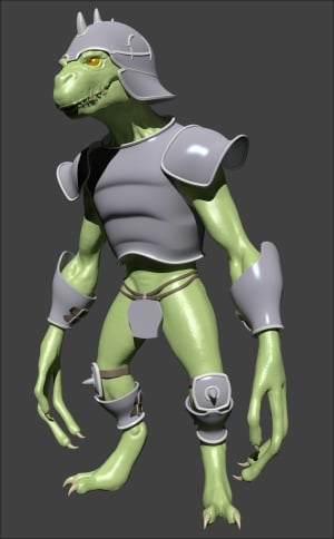
The completed armor as it appears in the rendering
How to do it…
Assuming we have gone out of Edit Mode and then saved the file, reopen the Gidiosaurus_modeling.blend file and proceed with the following:
- Go back in Edit Mode and select the edge-loop around the neck (Alt + right-click), the edge-loop around the shoulder hole (Alt + Shift + right-click), and the last one at the base of the Breastplate (Alt + Shift + right-click again).
- Press Shift + D and soon after, the right-mouse button to duplicate without moving them; press P to separate them (in the Separate pop-up menu, choose the Selection item):
Separating geometry by selection
- Go out of Edit Mode to select the Breastplate.001 object (the duplicated edge-loops).
- Press Alt + C and in the Convert to pop-up menu, select the first item: Curve from Mesh/Text.
- The mesh edge-loops actually get converted into Curve objects, as you can see in the Object Data window under the main Properties panel on the right-hand side of the UI:
Converting the geometry in Curves
- In the Object Data window, under the Geometry tab, set the Extrude value to 0.002 and the Depth value to 0.010; then, under the Shape tab, set the Fill mode to Full:
"Modeling" the Curves by the settings
- Press Alt + C and this time, in the Convert to pop-up menu, select the second item: Mesh from Curve/Meta/Surf/Text.
- Press Tab to go in Edit Mode, press A to select all the vertices, and in the Mesh Tools tab under the Tools tab in the Tool Shelf panel, click on the Remove Doubles button (note that in the top main header, a message appears: Removed 2240 vertices; so always remember to remove the doubles after a conversion!).
- Go out of Edit Mode and click on the Smooth button in the Edit subpanel; in the Outliner, rename it as Breastplate_decorations.
- Assign a Subdivision Surface modifier, with the Subdivision level as 2 and Optimal Display enabled.
- Go to the Material window and assign a new material; rename it as
Armor_lightand copy all the settings and options from theArmor_darkmaterial, except for the diffuse and the specular colors—set them to RGB 1.000 (pure white; a faster way is to assign theArmor_darkmaterial, make it a single user, change the colors to white, and rename the material asArmor_light).Assigning a new material
- As always, remember to save the file.
Even if at first sight this seems a complex process, actually it's one of the easiest and fastest ways to model a mesh. We have just duplicated the edge-loops that are located where we had the intention of adding the modeled borders. With a simple shortcut, we have converted them to a curve object that can be beveled both by other curve objects or simply by values to be inserted in the fields under the Geometry tab. Then, once we obtained the shape we wanted, we converted the curve back to a mesh object.
We could have kept the armor decorations as curves, but by converting them to meshes, we have the opportunity to unwrap them for the mapping of the textures according to the rest of the armor.
Note that the Preview U value under the Resolution item in the Shape subpanel for the curve objects should be kept low if you don't want a resulting mesh with a lot of vertices; you can set it quite lower than the default 12. Just experiment before the final conversion, while keeping in mind that once converted to mesh, the decorations will probably be smoothed by a Subdivision Surface modifier with the rest of the armor; in any case, the obtained decorations mesh can also be simplified at a successive stage.
In this chapter, we saw the process that can be used to model the armor meshes. We will not demonstrate the rest of the armor modeling, as the same techniques can be used over again. However, feel free to model the rest of the armor on your own or have a look at the provided Gidiosaurus_modeling_02.blend file:
The completed armor as it appears in the rendering
How it works…
Even if at first sight this seems a complex process, actually it's one of the easiest and fastest ways to model a mesh. We have just duplicated the edge-loops that are located where we had the intention of adding the modeled borders. With a simple shortcut, we have converted them to a curve object that can be beveled both by other curve objects or simply by values to be inserted in the fields under the Geometry tab. Then, once we obtained the shape we wanted, we converted the curve back to a mesh object.
We could have kept the armor decorations as curves, but by converting them to meshes, we have the opportunity to unwrap them for the mapping of the textures according to the rest of the armor.
Note that the Preview U value under the Resolution item in the Shape subpanel for the curve objects should be kept low if you don't want a resulting mesh with a lot of vertices; you can set it quite lower than the default 12. Just experiment before the final conversion, while keeping in mind that once converted to mesh, the decorations will probably be smoothed by a Subdivision Surface modifier with the rest of the armor; in any case, the obtained decorations mesh can also be simplified at a successive stage.
In this chapter, we saw the process that can be used to model the armor meshes. We will not demonstrate the rest of the armor modeling, as the same techniques can be used over again. However, feel free to model the rest of the armor on your own or have a look at the provided Gidiosaurus_modeling_02.blend file:
The completed armor as it appears in the rendering
In this chapter, we will cover the following recipes:
- Using the Grease Pencil tool to plan the edge-loops flow
- Using the Snap tool to re-topologize the mesh
- Using the Shrinkwrap modifier to re-topologize the mesh
- Using the LoopTools add-on to re-topologize the mesh
- Concluding the re-topologized mesh
The re-topology of a mesh, as the name itself explains, is simply the reconstruction of that mesh with a different topology; usually, the re-topology is used to obtain a low resolution mesh from a high resolution one.
In our case, this is obviously needed because we are later going to rig and animate our Gidiosaurus, and these tasks would be almost impossible with a mesh as dense as the high resolution sculpted one; we not only need to reconstruct the shape of the mesh with a lower number of vertices, but also with the edge-loops properly placed and flowing for the best render and deformation of the character's features.
In Blender, we have several tools to accomplish this task, both hardcoded into the software or as add-ons to be enabled, and in this chapter, we are going to see them.
It would be perfectly possible to start immediately to re-topologize the high resolution mesh, at least for an expert modeler; by the way, it's usually a good practice to have a guide to be followed in the process, to solve a priori any issue (or at least most of them) that we would come across.
So, let's start this chapter by planning what the right topology can be for a low resolution mesh of our Gidiosaurus character; we are going to use the Grease Pencil tool to draw the paths of the edge-loops and polygons flow, straight onto the sculpted mesh.
First, let's prepare the screen:
- Open the
Gidiosaurus_modeling_02.blendfile. - Go to the UV/Image Editor window to the left and Shift + left-click on the X icon on the toolbar to get rid of the template image (to be more technically precise, to unlink the template image data block; the Shift key is to set the users to 0 and definitely eliminate the image from the file).
- Put the mouse pointer on the border between the two windows and right-click; in the little Area Options pop-up panel, left-click on the Join Area item and then slightly move the mouse pointer to the left and left-click again, to join the two windows and obtain a single big 3D viewport window:

Joining the two windows into one
- Click on the 11th scene layer button to show only the sculpted Gidiosaurus mesh and parts such as the teeth, eyes, and so on.
- Go to the Outliner and click on the icons showing an eye image placed to the right side of the Eyeballs, Fangs, and Talons items to hide them.
- Press the N key to make the Properties 3D view sidepanel appear to the right of the 3D window and scroll it to find the Grease Pencil subpanel (already enabled by default); go to the Tool Shelf panel to the left of the 3D window and click on the Grease Pencil tab:

The Grease Pencil panels and the screen layout in current state
- Check to enable the Continuous Drawing item just below the four buttons at the top of the Grease Pencil tab on the Tool Shelf.
- Go to the Grease Pencil subpanel under the Properties 3D view sidepanel to the right and click on the New button; then, click on the + icon button to the left side to add a new Grease Pencil layer, which is by default labeled GP_Layer; set the Stroke color to RGB 1.000, 0.000, 0.350 and Thickness of the strokes to 4 pixels.
- Double-click on the GP_Layer name to rename it as Head.
- Go to the Tool Shelf and, under Stroke Placement, click on the Surface button:

Starting to use the Grease Pencil tool
- Save the file as
Gidiosaurus_retopology.blend.
We are now going to start to draw on the character's head:
- Press Shift + B and draw a box around the head of the Gidiosaurus to zoom to it; then, press the 5 key on the numpad to go into Ortho view.
- Click on the Draw, Line or Poly buttons at the top of the Grease Pencil tab in the Tool Shelf; alternatively, keep the D key pressed (along with left-click) to start to draw the first stroke on the mesh (Ctrl + D + left-click and Ctrl + D + right-click, respectively for Line and Poly).
Because we enabled the Continuous Drawing item in the Tool Shelf, we can continue to draw without the need to reactivate the drawing mode at each stroke. To quit the sketching session (for example, to change the brush), we can press the Esc or the Enter keys, so confirming the sketching session itself at the same time; otherwise, without the Continuous Drawing item enabled, the sketching is confirmed right after each stroke.
- Start to draw (one half side of the mesh is enough) the strokes; try to make the strokes follow the main, basic, and more remarkable features of the sculpted mesh such as the main skin folders going from the snout to the eye sockets and the bags under the eyes, nostril, mouth rim, and so on.
- Don't worry too much about the quality or the precision of the strokes; also, don't be afraid to erase (D + right-click or the Erase button) and/or correct the strokes, if necessary. The Grease Pencil, in this case, is just a tool to sketch directly on the mesh the guidelines we will later follow for the re-topology stage:

Drawing the head's main features topology
In the case of our Gidiosaurus, the topology for a correct deformation is similar to the topology we would use for a human face, but a lot simpler: we just need edge-loops around the eyes and in the eyebrows area, to give them mobility for expressiveness; a few edge-loops around the mouth that, however, in our case, remains quite rigid; and edge-loops following the folders on the top of the snout, which can also be important for the growl expression.
- Once the strokes for the main features have been posed, try to join them into a web of edges, as balanced and efficient as possible:

Connecting the strokes
- At a certain point, when and if the overlapping of the strokes starts to become confusing, you can uncheck the X Ray item, which is located to the right side of the Thickness slot in the Grease Pencil layer subpanel, to disable the visibility of the strokes behind the mesh surface.
- Forget about the edge-loops of stiff parts such as the cranium; it's enough to plan the position and the flow of the deforming ones. In the screenshot at the bottom right, I have highlighted (in Gimp) the main facial edge-loops for the Gidiosaurus with different colors:

The X Ray button and the highlighted main edge-loops
- When you think you are done with the head, click on the + icon button to add a new layer and rename it as Neck. Set the values the same you did for the Head layer, just change the color of the strokes; I set mine to RGB 0.106, 0.435, 0.993, but whatever color you choose, be sure that it stands out in the viewport against the mesh color.
- In the case of the neck, the important thing is to find the correct joining with the head's edge-loops under the lower jaw, as you can see in the bottom-right screenshot:

The Neck layer
- Continue to stroke on the neck by drawing parallel horizontal loops along its length and use the vertical strokes to outline the neck's muscles (don't look for a sternocleidomastoid muscle here; the Gidiosaurus, anatomy, although similar in some ways, is not human at all!).
- Remember that because our character is wearing an armor, it is not necessary to re-topologize the whole body, but only the exposed parts; so we can stop the planning just a little beyond the plates outside edges. To verify the correct extension of the strokes, just be sure to have the X Ray item enabled in the Grease Pencil layers and also the 13th scene layer enabled to show the armor:

Verifying the extension of the strokes under the armor
- Click again on the + icon button in the Grease Pencil subpanel under the Properties 3D view sidepanel and rename the new layer as Arm. Set the values the same as you did for the Head and Neck layers, but change the color once more (R 0.000, G 1.000, B 0.476); this time, we have to plan the joining of the cylindrical shape of the arm with the shoulder and the collar bones areas:

Sketching the guidelines on the arm
- As before, also in this case, it is not necessary to go beyond the boundaries of the armor chest plate, but including also the muscles of the chest and back in the topology planning can give a more natural result:

The completed guidelines for the shoulder and the arm joining
- When you are done, save the file.
At this point, we can stop with the Grease Pencil sketching of the topology; the remaining parts of the exposed body are a lot simpler and will be quickly resolved in the successive recipe of this chapter.
We can load any already existing Grease Pencil layer data blocks even into an empty scene, by clicking on the little arrows on the left-hand side of the Gpencil slot (Freehand annotation sketchbook) at the top of the Grease Pencil subpanel on the Properties 3D view sidepanel, and indifferently for Scene or Object. Actually, the Grease Pencil tool can be used as a sketchbook tool, to write quick notes and/or corrections inside the Node Editor window or the UV/Image Editor window, and even as an animation tool, by drawing inside an empty scene or on the surface of other objects to be used as templates.
In the following screenshot, you can see the sketching sessions previously made on the Gidiosaurus object's surface, showing a solo and keeping the volumes of the character in the 3D space:
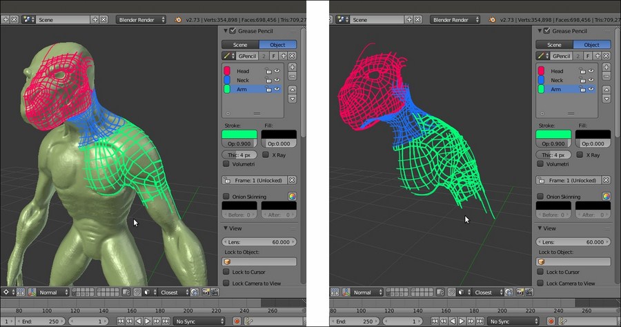
The Grease Pencil layers in the 3D space
Getting ready
First, let's prepare the screen:
- Open the
Gidiosaurus_modeling_02.blendfile. - Go to the UV/Image Editor window to the left and Shift + left-click on the X icon on the toolbar to get rid of the template image (to be more technically precise, to unlink the template image data block; the Shift key is to set the users to 0 and definitely eliminate the image from the file).
- Put the mouse pointer on the border between the two windows and right-click; in the little Area Options pop-up panel, left-click on the Join Area item and then slightly move the mouse pointer to the left and left-click again, to join the two windows and obtain a single big 3D viewport window:
Joining the two windows into one
- Click on the 11th scene layer button to show only the sculpted Gidiosaurus mesh and parts such as the teeth, eyes, and so on.
- Go to the Outliner and click on the icons showing an eye image placed to the right side of the Eyeballs, Fangs, and Talons items to hide them.
- Press the N key to make the Properties 3D view sidepanel appear to the right of the 3D window and scroll it to find the Grease Pencil subpanel (already enabled by default); go to the Tool Shelf panel to the left of the 3D window and click on the Grease Pencil tab:
The Grease Pencil panels and the screen layout in current state
- Check to enable the Continuous Drawing item just below the four buttons at the top of the Grease Pencil tab on the Tool Shelf.
- Go to the Grease Pencil subpanel under the Properties 3D view sidepanel to the right and click on the New button; then, click on the + icon button to the left side to add a new Grease Pencil layer, which is by default labeled GP_Layer; set the Stroke color to RGB 1.000, 0.000, 0.350 and Thickness of the strokes to 4 pixels.
- Double-click on the GP_Layer name to rename it as Head.
- Go to the Tool Shelf and, under Stroke Placement, click on the Surface button:
Starting to use the Grease Pencil tool
- Save the file as
Gidiosaurus_retopology.blend.
We are now going to start to draw on the character's head:
- Press Shift + B and draw a box around the head of the Gidiosaurus to zoom to it; then, press the 5 key on the numpad to go into Ortho view.
- Click on the Draw, Line or Poly buttons at the top of the Grease Pencil tab in the Tool Shelf; alternatively, keep the D key pressed (along with left-click) to start to draw the first stroke on the mesh (Ctrl + D + left-click and Ctrl + D + right-click, respectively for Line and Poly).
Because we enabled the Continuous Drawing item in the Tool Shelf, we can continue to draw without the need to reactivate the drawing mode at each stroke. To quit the sketching session (for example, to change the brush), we can press the Esc or the Enter keys, so confirming the sketching session itself at the same time; otherwise, without the Continuous Drawing item enabled, the sketching is confirmed right after each stroke.
- Start to draw (one half side of the mesh is enough) the strokes; try to make the strokes follow the main, basic, and more remarkable features of the sculpted mesh such as the main skin folders going from the snout to the eye sockets and the bags under the eyes, nostril, mouth rim, and so on.
- Don't worry too much about the quality or the precision of the strokes; also, don't be afraid to erase (D + right-click or the Erase button) and/or correct the strokes, if necessary. The Grease Pencil, in this case, is just a tool to sketch directly on the mesh the guidelines we will later follow for the re-topology stage:
Drawing the head's main features topology
In the case of our Gidiosaurus, the topology for a correct deformation is similar to the topology we would use for a human face, but a lot simpler: we just need edge-loops around the eyes and in the eyebrows area, to give them mobility for expressiveness; a few edge-loops around the mouth that, however, in our case, remains quite rigid; and edge-loops following the folders on the top of the snout, which can also be important for the growl expression.
- Once the strokes for the main features have been posed, try to join them into a web of edges, as balanced and efficient as possible:
Connecting the strokes
- At a certain point, when and if the overlapping of the strokes starts to become confusing, you can uncheck the X Ray item, which is located to the right side of the Thickness slot in the Grease Pencil layer subpanel, to disable the visibility of the strokes behind the mesh surface.
- Forget about the edge-loops of stiff parts such as the cranium; it's enough to plan the position and the flow of the deforming ones. In the screenshot at the bottom right, I have highlighted (in Gimp) the main facial edge-loops for the Gidiosaurus with different colors:
The X Ray button and the highlighted main edge-loops
- When you think you are done with the head, click on the + icon button to add a new layer and rename it as Neck. Set the values the same you did for the Head layer, just change the color of the strokes; I set mine to RGB 0.106, 0.435, 0.993, but whatever color you choose, be sure that it stands out in the viewport against the mesh color.
- In the case of the neck, the important thing is to find the correct joining with the head's edge-loops under the lower jaw, as you can see in the bottom-right screenshot:
The Neck layer
- Continue to stroke on the neck by drawing parallel horizontal loops along its length and use the vertical strokes to outline the neck's muscles (don't look for a sternocleidomastoid muscle here; the Gidiosaurus, anatomy, although similar in some ways, is not human at all!).
- Remember that because our character is wearing an armor, it is not necessary to re-topologize the whole body, but only the exposed parts; so we can stop the planning just a little beyond the plates outside edges. To verify the correct extension of the strokes, just be sure to have the X Ray item enabled in the Grease Pencil layers and also the 13th scene layer enabled to show the armor:
Verifying the extension of the strokes under the armor
- Click again on the + icon button in the Grease Pencil subpanel under the Properties 3D view sidepanel and rename the new layer as Arm. Set the values the same as you did for the Head and Neck layers, but change the color once more (R 0.000, G 1.000, B 0.476); this time, we have to plan the joining of the cylindrical shape of the arm with the shoulder and the collar bones areas:
Sketching the guidelines on the arm
- As before, also in this case, it is not necessary to go beyond the boundaries of the armor chest plate, but including also the muscles of the chest and back in the topology planning can give a more natural result:
The completed guidelines for the shoulder and the arm joining
- When you are done, save the file.
At this point, we can stop with the Grease Pencil sketching of the topology; the remaining parts of the exposed body are a lot simpler and will be quickly resolved in the successive recipe of this chapter.
We can load any already existing Grease Pencil layer data blocks even into an empty scene, by clicking on the little arrows on the left-hand side of the Gpencil slot (Freehand annotation sketchbook) at the top of the Grease Pencil subpanel on the Properties 3D view sidepanel, and indifferently for Scene or Object. Actually, the Grease Pencil tool can be used as a sketchbook tool, to write quick notes and/or corrections inside the Node Editor window or the UV/Image Editor window, and even as an animation tool, by drawing inside an empty scene or on the surface of other objects to be used as templates.
In the following screenshot, you can see the sketching sessions previously made on the Gidiosaurus object's surface, showing a solo and keeping the volumes of the character in the 3D space:
The Grease Pencil layers in the 3D space
How to do it…
We are now going to start to draw on the character's head:
- Press Shift + B and draw a box around the head of the Gidiosaurus to zoom to it; then, press the 5 key on the numpad to go into Ortho view.
- Click on the Draw, Line or Poly buttons at the top of the Grease Pencil tab in the Tool Shelf; alternatively, keep the D key pressed (along with left-click) to start to draw the first stroke on the mesh (Ctrl + D + left-click and Ctrl + D + right-click, respectively for Line and Poly).
Because we enabled the Continuous Drawing item in the Tool Shelf, we can continue to draw without the need to reactivate the drawing mode at each stroke. To quit the sketching session (for example, to change the brush), we can press the Esc or the Enter keys, so confirming the sketching session itself at the same time; otherwise, without the Continuous Drawing item enabled, the sketching is confirmed right after each stroke.
- Start to draw (one half side of the mesh is enough) the strokes; try to make the strokes follow the main, basic, and more remarkable features of the sculpted mesh such as the main skin folders going from the snout to the eye sockets and the bags under the eyes, nostril, mouth rim, and so on.
- Don't worry too much about the quality or the precision of the strokes; also, don't be afraid to erase (D + right-click or the Erase button) and/or correct the strokes, if necessary. The Grease Pencil, in this case, is just a tool to sketch directly on the mesh the guidelines we will later follow for the re-topology stage:
Drawing the head's main features topology
In the case of our Gidiosaurus, the topology for a correct deformation is similar to the topology we would use for a human face, but a lot simpler: we just need edge-loops around the eyes and in the eyebrows area, to give them mobility for expressiveness; a few edge-loops around the mouth that, however, in our case, remains quite rigid; and edge-loops following the folders on the top of the snout, which can also be important for the growl expression.
- Once the strokes for the main features have been posed, try to join them into a web of edges, as balanced and efficient as possible:
Connecting the strokes
- At a certain point, when and if the overlapping of the strokes starts to become confusing, you can uncheck the X Ray item, which is located to the right side of the Thickness slot in the Grease Pencil layer subpanel, to disable the visibility of the strokes behind the mesh surface.
- Forget about the edge-loops of stiff parts such as the cranium; it's enough to plan the position and the flow of the deforming ones. In the screenshot at the bottom right, I have highlighted (in Gimp) the main facial edge-loops for the Gidiosaurus with different colors:
The X Ray button and the highlighted main edge-loops
- When you think you are done with the head, click on the + icon button to add a new layer and rename it as Neck. Set the values the same you did for the Head layer, just change the color of the strokes; I set mine to RGB 0.106, 0.435, 0.993, but whatever color you choose, be sure that it stands out in the viewport against the mesh color.
- In the case of the neck, the important thing is to find the correct joining with the head's edge-loops under the lower jaw, as you can see in the bottom-right screenshot:
The Neck layer
- Continue to stroke on the neck by drawing parallel horizontal loops along its length and use the vertical strokes to outline the neck's muscles (don't look for a sternocleidomastoid muscle here; the Gidiosaurus, anatomy, although similar in some ways, is not human at all!).
- Remember that because our character is wearing an armor, it is not necessary to re-topologize the whole body, but only the exposed parts; so we can stop the planning just a little beyond the plates outside edges. To verify the correct extension of the strokes, just be sure to have the X Ray item enabled in the Grease Pencil layers and also the 13th scene layer enabled to show the armor:
Verifying the extension of the strokes under the armor
- Click again on the + icon button in the Grease Pencil subpanel under the Properties 3D view sidepanel and rename the new layer as Arm. Set the values the same as you did for the Head and Neck layers, but change the color once more (R 0.000, G 1.000, B 0.476); this time, we have to plan the joining of the cylindrical shape of the arm with the shoulder and the collar bones areas:
Sketching the guidelines on the arm
- As before, also in this case, it is not necessary to go beyond the boundaries of the armor chest plate, but including also the muscles of the chest and back in the topology planning can give a more natural result:
The completed guidelines for the shoulder and the arm joining
- When you are done, save the file.
At this point, we can stop with the Grease Pencil sketching of the topology; the remaining parts of the exposed body are a lot simpler and will be quickly resolved in the successive recipe of this chapter.
We can load any already existing Grease Pencil layer data blocks even into an empty scene, by clicking on the little arrows on the left-hand side of the Gpencil slot (Freehand annotation sketchbook) at the top of the Grease Pencil subpanel on the Properties 3D view sidepanel, and indifferently for Scene or Object. Actually, the Grease Pencil tool can be used as a sketchbook tool, to write quick notes and/or corrections inside the Node Editor window or the UV/Image Editor window, and even as an animation tool, by drawing inside an empty scene or on the surface of other objects to be used as templates.
In the following screenshot, you can see the sketching sessions previously made on the Gidiosaurus object's surface, showing a solo and keeping the volumes of the character in the 3D space:
The Grease Pencil layers in the 3D space
There's more…
We can load any already existing Grease Pencil layer data blocks even into an empty scene, by clicking on the little arrows on the left-hand side of the Gpencil slot (Freehand annotation sketchbook) at the top of the Grease Pencil subpanel on the Properties 3D view sidepanel, and indifferently for Scene or Object. Actually, the Grease Pencil tool can be used as a sketchbook tool, to write quick notes and/or corrections inside the Node Editor window or the UV/Image Editor window, and even as an animation tool, by drawing inside an empty scene or on the surface of other objects to be used as templates.
In the following screenshot, you can see the sketching sessions previously made on the Gidiosaurus object's surface, showing a solo and keeping the volumes of the character in the 3D space:
The Grease Pencil layers in the 3D space
In this recipe, we'll use the Snap tool to start to re-topologize the sculpted high resolution mesh.
First, let's prepare both, the mesh to be traced, which is the high resolution mesh, and the tool itself:
- Go to the Outliner and click on the Restrict viewport selection icon, which is the arrow one, to the side of the Gidiosaurus item to make it not selectable.
- Be sure that the 3D Cursor is at the center of the scene (Shift + C) and add a Plane primitive.
- Click on the Snap during transform button, the little icon with the magnet, on the 3D view toolbar, or else press Shift + Tab to activate the tool.
- Click on the Snap Element button (Type of element to snap to) on the close right to select the Face item, or else press Shift + Ctrl + Tab to make the Snap Element pop-up menu appear in order to select the item from:

The Snap Element menu
Now, we are going to start the re-topology:
- With the Plane object selected, press Tab to go into Edit Mode; with all the vertices already selected by default, by pressing Shift + right-click, deselect just one vertex (anyone of them, it doesn't matter which one).
- Press X to delete the other three vertices that are still selected.
- Select the single remaining vertex and move it onto the head of the sculpted mesh, close to the left eye socket; as the Snap tool is enabled, the vertex stays on the mesh surface.
- Press the period (.) key on the numpad to zoom the 3D view centered on the selected vertex:

Starting the re-topology process
- Go to the Object Data window and check the X-Ray item under the Display subpanel in the main Properties panel to the right of the screen.
- Start to extrude the vertex, building an edge-loop around the eye socket and following the Grease Pencil guideline, both by pressing the E key or Ctrl + left-click to add vertices; if needed, press G to move them at the right location (that is, at the intersections of the guidelines).
- When you have almost completed the edge-loop around the eye socket, select the last and the first vertices and press the F key to close it.
- Select the bottom row of vertices of the edge-loop and extrude them; adjust the position of each vertex on the ground of the strokes guideline:

The first re-topology around the eye socket
- Do the same with the upper row of vertices and then select the free vertices on the right-hand side of the edge-loops and press Alt + M to merge them at the center (At Center):

Building the eye edge-loop
- While still in Edit Mode, select all the vertices and press Ctrl + N to recalculate the normals.
- Keep on extruding the edge-loops to build the faces around the eye socket. Select the inner edge-loop and extrude it; then, scale it inside and adjust the vertices position as usual.
- Cut a new edge-loop in the middle of the eye socket by pressing Ctrl + R and then select each vertex; press G and, immediately after, click with the left button of the mouse. This way the newly added vertex stays in place, but is snapped to the underlying surface (sadly, it doesn't work automatically as you cut or add vertices; they must be moved in some way to make the Snap tool work).

Adding geometry and snapping the vertices to the surface
- Keep on adding geometry to the mesh, extruding or Ctrl + left-clicking, and switch between edges and vertices selection mode to make the workflow faster. Press 5 on the numpad to go into Ortho view when necessary. Following the strokes guideline, build faces going towards the median line of the object.
- As you are arrived to the median line of the object, go to the Object Modifiers window under the Properties panel and assign a Mirror modifier.
- Click on the Adjust edit cage to modifier result icon (the last one in the row to the side of the modifier's name), to activate the modifier during the editing, and check the Clipping item.
- Adjust the vertices you just added to the median line of the mesh to stay on the y axis and recalculate the normals.
- Go to the Outliner and rename the Plane item as Gidiosaurus_lowres.

Going towards the median line
- Build the remainder of the faces the same way, extruding edges or vertices, moving them to react to the Snap tool, and adding cuts and edge-loops where needed to keep all quads. N-gons faces can be split into quads by dividing an edge to add a vertex in the middle, selecting the new vertex and its opposite one and pressing the J key to connect them (see the two screenshots at the bottom row):

Building the eyebrows and dividing N-gons into two quad faces
- Assign a Subdivision Surface modifier to the low resolution mesh and set Subdivisions to 2. Check the Optimal Display item; if you want, click on the Adjust edit cage to modifier result icon, which is the last one in the row to the side of the modifier's name. To work with an already smoothed mesh (in the end, the mesh will be subdivided in any case) is a usual workflow; by the way, it depends on your preferences. If you prefer to work without the modifier, occasionally go out of Edit Mode to verify how the geometry behaves under the Subdivision Surface modifier.

The created geometry in the Subdivision Surface visualization mode
- Around the eyebrows, it is important to have continuous edge-loops to allow for better mesh deformation; often, it is enough to merge (Alt + M) two vertices to obtain the right flow. Note that this creates a pole (check out the screenshot at the top right) that can later be eliminated by a cut and then merges the two tris faces into a quad (Alt + J; the two screenshots at the bottom):

Closing two edge-loops
- We have almost completed the Gidiosaurus' face. Select the vertices of the lower jaw and press the H key to hide them; select the upper mouth rim and extrude it and then adjust the vertices' position.
- Deselect the vertices, press Alt + H to unhide the mandible, and press Shift + H to hide the unselected vertices (in this case, the upper face). Select the mouth rim of the mandible and extrude and then tweak the position of the vertices.
- Connect the upper and the lower jaws by connecting the last vertices, as shown in the bottom-left of screenshot and then build a face. Tweak the vertices' position:

Connecting the jaw to the upper mouth
We can stop using the Snap tool at this point and continue with the re-topologizing by using different tools; we'll see this in the upcoming recipes.
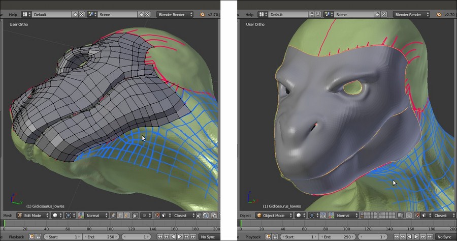
The re-topologized face of the character
The main requirement for a re-topology tool is the ability to trace the shape and volume of the high resolution mesh as easily as possible. In this recipe, we used the Blender Snap tool that, once set to Face, guarantees that every added vertex lies on the faces of any directly underlying object; this way, it is quite simple to concentrate on the flow of the polygons, while their vertices stay anchored to the mesh's surface.
To remark that the strokes are there only as a generic indication, note that in certain areas we are doubling the number of faces sketched with the Grease Pencil tool as well as to try to keep the density of the mesh as even as possible.
Getting ready
First, let's prepare both, the mesh to be traced, which is the high resolution mesh, and the tool itself:
- Go to the Outliner and click on the Restrict viewport selection icon, which is the arrow one, to the side of the Gidiosaurus item to make it not selectable.
- Be sure that the 3D Cursor is at the center of the scene (Shift + C) and add a Plane primitive.
- Click on the Snap during transform button, the little icon with the magnet, on the 3D view toolbar, or else press Shift + Tab to activate the tool.
- Click on the Snap Element button (Type of element to snap to) on the close right to select the Face item, or else press Shift + Ctrl + Tab to make the Snap Element pop-up menu appear in order to select the item from:
The Snap Element menu
Now, we are going to start the re-topology:
- With the Plane object selected, press Tab to go into Edit Mode; with all the vertices already selected by default, by pressing Shift + right-click, deselect just one vertex (anyone of them, it doesn't matter which one).
- Press X to delete the other three vertices that are still selected.
- Select the single remaining vertex and move it onto the head of the sculpted mesh, close to the left eye socket; as the Snap tool is enabled, the vertex stays on the mesh surface.
- Press the period (.) key on the numpad to zoom the 3D view centered on the selected vertex:
Starting the re-topology process
- Go to the Object Data window and check the X-Ray item under the Display subpanel in the main Properties panel to the right of the screen.
- Start to extrude the vertex, building an edge-loop around the eye socket and following the Grease Pencil guideline, both by pressing the E key or Ctrl + left-click to add vertices; if needed, press G to move them at the right location (that is, at the intersections of the guidelines).
- When you have almost completed the edge-loop around the eye socket, select the last and the first vertices and press the F key to close it.
- Select the bottom row of vertices of the edge-loop and extrude them; adjust the position of each vertex on the ground of the strokes guideline:
The first re-topology around the eye socket
- Do the same with the upper row of vertices and then select the free vertices on the right-hand side of the edge-loops and press Alt + M to merge them at the center (At Center):
Building the eye edge-loop
- While still in Edit Mode, select all the vertices and press Ctrl + N to recalculate the normals.
- Keep on extruding the edge-loops to build the faces around the eye socket. Select the inner edge-loop and extrude it; then, scale it inside and adjust the vertices position as usual.
- Cut a new edge-loop in the middle of the eye socket by pressing Ctrl + R and then select each vertex; press G and, immediately after, click with the left button of the mouse. This way the newly added vertex stays in place, but is snapped to the underlying surface (sadly, it doesn't work automatically as you cut or add vertices; they must be moved in some way to make the Snap tool work).
Adding geometry and snapping the vertices to the surface
- Keep on adding geometry to the mesh, extruding or Ctrl + left-clicking, and switch between edges and vertices selection mode to make the workflow faster. Press 5 on the numpad to go into Ortho view when necessary. Following the strokes guideline, build faces going towards the median line of the object.
- As you are arrived to the median line of the object, go to the Object Modifiers window under the Properties panel and assign a Mirror modifier.
- Click on the Adjust edit cage to modifier result icon (the last one in the row to the side of the modifier's name), to activate the modifier during the editing, and check the Clipping item.
- Adjust the vertices you just added to the median line of the mesh to stay on the y axis and recalculate the normals.
- Go to the Outliner and rename the Plane item as Gidiosaurus_lowres.
Going towards the median line
- Build the remainder of the faces the same way, extruding edges or vertices, moving them to react to the Snap tool, and adding cuts and edge-loops where needed to keep all quads. N-gons faces can be split into quads by dividing an edge to add a vertex in the middle, selecting the new vertex and its opposite one and pressing the J key to connect them (see the two screenshots at the bottom row):
Building the eyebrows and dividing N-gons into two quad faces
- Assign a Subdivision Surface modifier to the low resolution mesh and set Subdivisions to 2. Check the Optimal Display item; if you want, click on the Adjust edit cage to modifier result icon, which is the last one in the row to the side of the modifier's name. To work with an already smoothed mesh (in the end, the mesh will be subdivided in any case) is a usual workflow; by the way, it depends on your preferences. If you prefer to work without the modifier, occasionally go out of Edit Mode to verify how the geometry behaves under the Subdivision Surface modifier.
The created geometry in the Subdivision Surface visualization mode
- Around the eyebrows, it is important to have continuous edge-loops to allow for better mesh deformation; often, it is enough to merge (Alt + M) two vertices to obtain the right flow. Note that this creates a pole (check out the screenshot at the top right) that can later be eliminated by a cut and then merges the two tris faces into a quad (Alt + J; the two screenshots at the bottom):
Closing two edge-loops
- We have almost completed the Gidiosaurus' face. Select the vertices of the lower jaw and press the H key to hide them; select the upper mouth rim and extrude it and then adjust the vertices' position.
- Deselect the vertices, press Alt + H to unhide the mandible, and press Shift + H to hide the unselected vertices (in this case, the upper face). Select the mouth rim of the mandible and extrude and then tweak the position of the vertices.
- Connect the upper and the lower jaws by connecting the last vertices, as shown in the bottom-left of screenshot and then build a face. Tweak the vertices' position:
Connecting the jaw to the upper mouth
We can stop using the Snap tool at this point and continue with the re-topologizing by using different tools; we'll see this in the upcoming recipes.
The re-topologized face of the character
The main requirement for a re-topology tool is the ability to trace the shape and volume of the high resolution mesh as easily as possible. In this recipe, we used the Blender Snap tool that, once set to Face, guarantees that every added vertex lies on the faces of any directly underlying object; this way, it is quite simple to concentrate on the flow of the polygons, while their vertices stay anchored to the mesh's surface.
To remark that the strokes are there only as a generic indication, note that in certain areas we are doubling the number of faces sketched with the Grease Pencil tool as well as to try to keep the density of the mesh as even as possible.
How to do it…
Now, we are going to start the re-topology:
- With the Plane object selected, press Tab to go into Edit Mode; with all the vertices already selected by default, by pressing Shift + right-click, deselect just one vertex (anyone of them, it doesn't matter which one).
- Press X to delete the other three vertices that are still selected.
- Select the single remaining vertex and move it onto the head of the sculpted mesh, close to the left eye socket; as the Snap tool is enabled, the vertex stays on the mesh surface.
- Press the period (.) key on the numpad to zoom the 3D view centered on the selected vertex:
Starting the re-topology process
- Go to the Object Data window and check the X-Ray item under the Display subpanel in the main Properties panel to the right of the screen.
- Start to extrude the vertex, building an edge-loop around the eye socket and following the Grease Pencil guideline, both by pressing the E key or Ctrl + left-click to add vertices; if needed, press G to move them at the right location (that is, at the intersections of the guidelines).
- When you have almost completed the edge-loop around the eye socket, select the last and the first vertices and press the F key to close it.
- Select the bottom row of vertices of the edge-loop and extrude them; adjust the position of each vertex on the ground of the strokes guideline:
The first re-topology around the eye socket
- Do the same with the upper row of vertices and then select the free vertices on the right-hand side of the edge-loops and press Alt + M to merge them at the center (At Center):
Building the eye edge-loop
- While still in Edit Mode, select all the vertices and press Ctrl + N to recalculate the normals.
- Keep on extruding the edge-loops to build the faces around the eye socket. Select the inner edge-loop and extrude it; then, scale it inside and adjust the vertices position as usual.
- Cut a new edge-loop in the middle of the eye socket by pressing Ctrl + R and then select each vertex; press G and, immediately after, click with the left button of the mouse. This way the newly added vertex stays in place, but is snapped to the underlying surface (sadly, it doesn't work automatically as you cut or add vertices; they must be moved in some way to make the Snap tool work).
Adding geometry and snapping the vertices to the surface
- Keep on adding geometry to the mesh, extruding or Ctrl + left-clicking, and switch between edges and vertices selection mode to make the workflow faster. Press 5 on the numpad to go into Ortho view when necessary. Following the strokes guideline, build faces going towards the median line of the object.
- As you are arrived to the median line of the object, go to the Object Modifiers window under the Properties panel and assign a Mirror modifier.
- Click on the Adjust edit cage to modifier result icon (the last one in the row to the side of the modifier's name), to activate the modifier during the editing, and check the Clipping item.
- Adjust the vertices you just added to the median line of the mesh to stay on the y axis and recalculate the normals.
- Go to the Outliner and rename the Plane item as Gidiosaurus_lowres.
Going towards the median line
- Build the remainder of the faces the same way, extruding edges or vertices, moving them to react to the Snap tool, and adding cuts and edge-loops where needed to keep all quads. N-gons faces can be split into quads by dividing an edge to add a vertex in the middle, selecting the new vertex and its opposite one and pressing the J key to connect them (see the two screenshots at the bottom row):
Building the eyebrows and dividing N-gons into two quad faces
- Assign a Subdivision Surface modifier to the low resolution mesh and set Subdivisions to 2. Check the Optimal Display item; if you want, click on the Adjust edit cage to modifier result icon, which is the last one in the row to the side of the modifier's name. To work with an already smoothed mesh (in the end, the mesh will be subdivided in any case) is a usual workflow; by the way, it depends on your preferences. If you prefer to work without the modifier, occasionally go out of Edit Mode to verify how the geometry behaves under the Subdivision Surface modifier.
The created geometry in the Subdivision Surface visualization mode
- Around the eyebrows, it is important to have continuous edge-loops to allow for better mesh deformation; often, it is enough to merge (Alt + M) two vertices to obtain the right flow. Note that this creates a pole (check out the screenshot at the top right) that can later be eliminated by a cut and then merges the two tris faces into a quad (Alt + J; the two screenshots at the bottom):
Closing two edge-loops
- We have almost completed the Gidiosaurus' face. Select the vertices of the lower jaw and press the H key to hide them; select the upper mouth rim and extrude it and then adjust the vertices' position.
- Deselect the vertices, press Alt + H to unhide the mandible, and press Shift + H to hide the unselected vertices (in this case, the upper face). Select the mouth rim of the mandible and extrude and then tweak the position of the vertices.
- Connect the upper and the lower jaws by connecting the last vertices, as shown in the bottom-left of screenshot and then build a face. Tweak the vertices' position:
Connecting the jaw to the upper mouth
We can stop using the Snap tool at this point and continue with the re-topologizing by using different tools; we'll see this in the upcoming recipes.
The re-topologized face of the character
The main requirement for a re-topology tool is the ability to trace the shape and volume of the high resolution mesh as easily as possible. In this recipe, we used the Blender Snap tool that, once set to Face, guarantees that every added vertex lies on the faces of any directly underlying object; this way, it is quite simple to concentrate on the flow of the polygons, while their vertices stay anchored to the mesh's surface.
To remark that the strokes are there only as a generic indication, note that in certain areas we are doubling the number of faces sketched with the Grease Pencil tool as well as to try to keep the density of the mesh as even as possible.
How it works…
The main requirement for a re-topology tool is the ability to trace the shape and volume of the high resolution mesh as easily as possible. In this recipe, we used the Blender Snap tool that, once set to Face, guarantees that every added vertex lies on the faces of any directly underlying object; this way, it is quite simple to concentrate on the flow of the polygons, while their vertices stay anchored to the mesh's surface.
To remark that the strokes are there only as a generic indication, note that in certain areas we are doubling the number of faces sketched with the Grease Pencil tool as well as to try to keep the density of the mesh as even as possible.
Sometimes, the Snap tool is not enough or can be quite difficult to use because of a particular shape of the high resolution mesh; in these cases, the Shrinkwrap modifier can be very handy.
Basically, the usage of this method is all in the preparation of the modifier:
- Assign the Shrinkwrap modifier to the Gidiosaurus_lowres mesh and, in the modifier stack, move it before the Subdivision Surface modifier.
- Click on the Target field to select the Gidiosaurus mesh item and leave the Mode option to Nearest Surface Point (this seems to be the more efficient mode for this task; by the way, you can experiment with the other two modes that can reveal themselves useful in other situations).
- Enable the Display modifier in Edit mode and Adjust edit cage to modifier result buttons (the penultimate one and the last one to the right, with the cube and four selected vertices image and with the upside-down triangle and three vertices image, respectively) and the Keep Above Surface item.
- In Edit Mode, if it's necessary to make the low resolution mesh more easily visible against the high resolution one, change the Offset value to 0.001.
- Having the X-Ray item still active, go to the Shading subpanel under the Properties 3D view sidepanel and check the Backface Culling item:

The Shrinkwrap modifier panel
In Edit Mode, select, extrude, and move the vertices as required! The Shrinkwrap modifier will take care of keeping the vertices adhering to the target mesh surface.
If you are having issues, such as vertices jumping everywhere as you try to move them, try to disable the Snap tool. This is not always the case, but sometimes the combination of both the tool and the modifier can give unexpected results; other times, it can be the opposite.
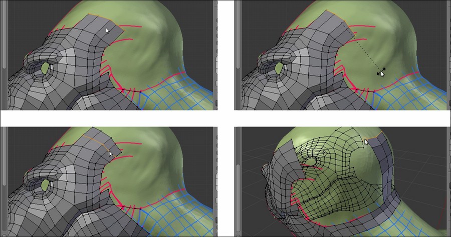
Extruding and cutting an edge-loop under the Shrinkwrap modifier
Remember that if you are using this method to re-topologize, at the end of the process, you must apply the Shrinkwrap modifier.
Also, save the file.
Getting ready
Basically, the usage of this method is all in the preparation of the modifier:
- Assign the Shrinkwrap modifier to the Gidiosaurus_lowres mesh and, in the modifier stack, move it before the Subdivision Surface modifier.
- Click on the Target field to select the Gidiosaurus mesh item and leave the Mode option to Nearest Surface Point (this seems to be the more efficient mode for this task; by the way, you can experiment with the other two modes that can reveal themselves useful in other situations).
- Enable the Display modifier in Edit mode and Adjust edit cage to modifier result buttons (the penultimate one and the last one to the right, with the cube and four selected vertices image and with the upside-down triangle and three vertices image, respectively) and the Keep Above Surface item.
- In Edit Mode, if it's necessary to make the low resolution mesh more easily visible against the high resolution one, change the Offset value to 0.001.
- Having the X-Ray item still active, go to the Shading subpanel under the Properties 3D view sidepanel and check the Backface Culling item:
The Shrinkwrap modifier panel
In Edit Mode, select, extrude, and move the vertices as required! The Shrinkwrap modifier will take care of keeping the vertices adhering to the target mesh surface.
If you are having issues, such as vertices jumping everywhere as you try to move them, try to disable the Snap tool. This is not always the case, but sometimes the combination of both the tool and the modifier can give unexpected results; other times, it can be the opposite.
Extruding and cutting an edge-loop under the Shrinkwrap modifier
Remember that if you are using this method to re-topologize, at the end of the process, you must apply the Shrinkwrap modifier.
Also, save the file.
How to do it…
In Edit Mode, select, extrude, and move the vertices as required! The Shrinkwrap modifier will take care of keeping the vertices adhering to the target mesh surface.
If you are having issues, such as vertices jumping everywhere as you try to move them, try to disable the Snap tool. This is not always the case, but sometimes the combination of both the tool and the modifier can give unexpected results; other times, it can be the opposite.
Extruding and cutting an edge-loop under the Shrinkwrap modifier
Remember that if you are using this method to re-topologize, at the end of the process, you must apply the Shrinkwrap modifier.
Also, save the file.
We have already seen the LoopTools add-on in Chapter 3, Polygonal Modeling of the Character's Accessories. This incredibly useful Python script can even be used for the re-topology!
If the LoopTools add-on isn't enabled yet, perform the following steps:
- Start Blender and call the Blender User Preferences panel (Ctrl + Alt + U); go to the Addons tab.
- Under the Categories item on the left-hand side of the panel, click on Mesh.
- Check the empty little box to the right of the Mesh: LoopTools add-on to enable it.
- Click on the Save User Settings button at the bottom-left of the panel to save your preferences and close the panel:

The User Preferences panel and the LoopTools add-on enabled
- Load the
Gidiosaurus_retopology.blendfile. - Click on the Snap during transform button on the 3D view toolbar (or else, press Shift + Tab) to enable the Snap tool again.
In the LoopTools add-on, there are at least three tools that can be used for the re-topology: Gstretch, Bridge, and Loft (the last two seem to have almost the same effect so, at least for our present goal, we can consider them to be interchangeable).
Let's first see the Gstretch tool:
- Go to the Grease Pencil subpanel under the Properties 3D view sidepanel to the right. Be sure that the Grease Pencil checkbox is checked and click on the + icon button to add a fourth layer after the Arm layer (actually, you can also delete the preexisting GPencil data block and start with a brand new one, or in any case disable the visibility of the other layers); leave the strokes color as it is by default—that is, pure black.
- In Edit Mode, press D and sketch one edge-loop stroke.
- Select the edges of the low resolution mesh and press E to extrude them and then right-click; click on the Gstretch button (or press W | Specials | LoopTools | Gstretch).
- In the last operator panel at the bottom of the Tool Shelf (or else, press F6 to make the pop-up window appear at the mouse cursor location), check the Delete strokes item.
- Press Ctrl + R to cut the required edge-loops in the new faces:

Using the Gstretch tool in conjunction with the Grease Pencil tool
Yes, it's that simple; it's enough to stroke the target position line and the new extruded vertices will be moved to that target position.
Also, now let's see the Bridge and the Loft tools:
- Select a group of edges and press Shift + D to duplicate them.
- Move them into a new position and adjust the vertices as required.
- Select both the new edges as the previous group.
- Go to the LoopTools panel and click on the Bridge button (or again, through the W key to call the Specials menu).

Using the Bridge tool
- If you need to add cuts, instead of the usual Ctrl + R shortcut, go to the last operator panel (F6) and change the value of the Segments slot to the number required.
It's not mandatory to duplicate new edges, it's enough to select the same number of vertices in the two edge-loops to be connected; here, after the Bridge tool operation, we have set the Segments value to 3:
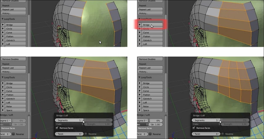
Adding cuts to the bridge operation
You can repeat the operation and the add-on will keep the last values you entered.
Repeat the steps, and this time click on the Loft button. The effect is almost the same, but if the new faces come out really messy, just click twice on the Reverse checkbox in the last operator panel; this should fix the issue.
You can then use all the other buttons to refine the added geometry; in the following screenshots, I tweaked the new geometry a little bit by selecting the horizontal edges and clicking on the Space, Flatten, and Relax buttons:
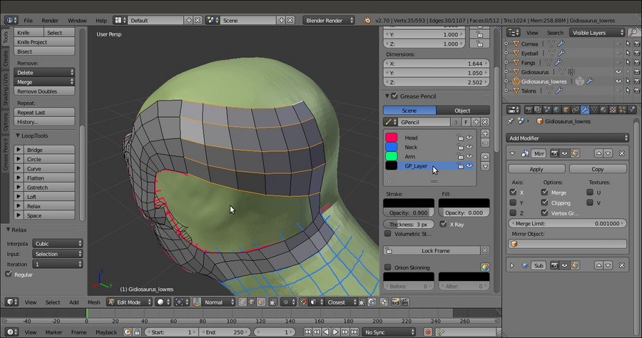
Completing the Gidiosaurus head
Using a mix of all the previous methods, in a short time, we have completed the head and the joining of the neck of our Gidiosaurus_lowres mesh; as you can see, particularly in the second screenshot at the bottom, the technique of following the main features and folders of the sculpted surface with the edge-loops can highlight the organic shapes even with a low resolution mesh:
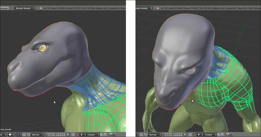
The completed head
Getting ready
If the LoopTools add-on isn't enabled yet, perform the following steps:
- Start Blender and call the Blender User Preferences panel (Ctrl + Alt + U); go to the Addons tab.
- Under the Categories item on the left-hand side of the panel, click on Mesh.
- Check the empty little box to the right of the Mesh: LoopTools add-on to enable it.
- Click on the Save User Settings button at the bottom-left of the panel to save your preferences and close the panel:
The User Preferences panel and the LoopTools add-on enabled
- Load the
Gidiosaurus_retopology.blendfile. - Click on the Snap during transform button on the 3D view toolbar (or else, press Shift + Tab) to enable the Snap tool again.
In the LoopTools add-on, there are at least three tools that can be used for the re-topology: Gstretch, Bridge, and Loft (the last two seem to have almost the same effect so, at least for our present goal, we can consider them to be interchangeable).
Let's first see the Gstretch tool:
- Go to the Grease Pencil subpanel under the Properties 3D view sidepanel to the right. Be sure that the Grease Pencil checkbox is checked and click on the + icon button to add a fourth layer after the Arm layer (actually, you can also delete the preexisting GPencil data block and start with a brand new one, or in any case disable the visibility of the other layers); leave the strokes color as it is by default—that is, pure black.
- In Edit Mode, press D and sketch one edge-loop stroke.
- Select the edges of the low resolution mesh and press E to extrude them and then right-click; click on the Gstretch button (or press W | Specials | LoopTools | Gstretch).
- In the last operator panel at the bottom of the Tool Shelf (or else, press F6 to make the pop-up window appear at the mouse cursor location), check the Delete strokes item.
- Press Ctrl + R to cut the required edge-loops in the new faces:
Using the Gstretch tool in conjunction with the Grease Pencil tool
Yes, it's that simple; it's enough to stroke the target position line and the new extruded vertices will be moved to that target position.
Also, now let's see the Bridge and the Loft tools:
- Select a group of edges and press Shift + D to duplicate them.
- Move them into a new position and adjust the vertices as required.
- Select both the new edges as the previous group.
- Go to the LoopTools panel and click on the Bridge button (or again, through the W key to call the Specials menu).
Using the Bridge tool
- If you need to add cuts, instead of the usual Ctrl + R shortcut, go to the last operator panel (F6) and change the value of the Segments slot to the number required.
It's not mandatory to duplicate new edges, it's enough to select the same number of vertices in the two edge-loops to be connected; here, after the Bridge tool operation, we have set the Segments value to 3:
Adding cuts to the bridge operation
You can repeat the operation and the add-on will keep the last values you entered.
Repeat the steps, and this time click on the Loft button. The effect is almost the same, but if the new faces come out really messy, just click twice on the Reverse checkbox in the last operator panel; this should fix the issue.
You can then use all the other buttons to refine the added geometry; in the following screenshots, I tweaked the new geometry a little bit by selecting the horizontal edges and clicking on the Space, Flatten, and Relax buttons:
Completing the Gidiosaurus head
Using a mix of all the previous methods, in a short time, we have completed the head and the joining of the neck of our Gidiosaurus_lowres mesh; as you can see, particularly in the second screenshot at the bottom, the technique of following the main features and folders of the sculpted surface with the edge-loops can highlight the organic shapes even with a low resolution mesh:
The completed head
How to do it…
In the LoopTools add-on, there are at least three tools that can be used for the re-topology: Gstretch, Bridge, and Loft (the last two seem to have almost the same effect so, at least for our present goal, we can consider them to be interchangeable).
Let's first see the Gstretch tool:
- Go to the Grease Pencil subpanel under the Properties 3D view sidepanel to the right. Be sure that the Grease Pencil checkbox is checked and click on the + icon button to add a fourth layer after the Arm layer (actually, you can also delete the preexisting GPencil data block and start with a brand new one, or in any case disable the visibility of the other layers); leave the strokes color as it is by default—that is, pure black.
- In Edit Mode, press D and sketch one edge-loop stroke.
- Select the edges of the low resolution mesh and press E to extrude them and then right-click; click on the Gstretch button (or press W | Specials | LoopTools | Gstretch).
- In the last operator panel at the bottom of the Tool Shelf (or else, press F6 to make the pop-up window appear at the mouse cursor location), check the Delete strokes item.
- Press Ctrl + R to cut the required edge-loops in the new faces:
Using the Gstretch tool in conjunction with the Grease Pencil tool
Yes, it's that simple; it's enough to stroke the target position line and the new extruded vertices will be moved to that target position.
Also, now let's see the Bridge and the Loft tools:
- Select a group of edges and press Shift + D to duplicate them.
- Move them into a new position and adjust the vertices as required.
- Select both the new edges as the previous group.
- Go to the LoopTools panel and click on the Bridge button (or again, through the W key to call the Specials menu).
Using the Bridge tool
- If you need to add cuts, instead of the usual Ctrl + R shortcut, go to the last operator panel (F6) and change the value of the Segments slot to the number required.
It's not mandatory to duplicate new edges, it's enough to select the same number of vertices in the two edge-loops to be connected; here, after the Bridge tool operation, we have set the Segments value to 3:
Adding cuts to the bridge operation
You can repeat the operation and the add-on will keep the last values you entered.
Repeat the steps, and this time click on the Loft button. The effect is almost the same, but if the new faces come out really messy, just click twice on the Reverse checkbox in the last operator panel; this should fix the issue.
You can then use all the other buttons to refine the added geometry; in the following screenshots, I tweaked the new geometry a little bit by selecting the horizontal edges and clicking on the Space, Flatten, and Relax buttons:
Completing the Gidiosaurus head
Using a mix of all the previous methods, in a short time, we have completed the head and the joining of the neck of our Gidiosaurus_lowres mesh; as you can see, particularly in the second screenshot at the bottom, the technique of following the main features and folders of the sculpted surface with the edge-loops can highlight the organic shapes even with a low resolution mesh:
The completed head
The Shrinkwrap modifier method can be the way to quickly finish the rest of the re-topology of the Gidiosaurus sculpted mesh, by quickly re-topologizing the simpler cylindrical shapes and then completing the more difficult parts by hand.
If necessary, repeat the steps to set up the Shrinkwrap modifier technique:
- Assign the Shrinkwrap modifier to the Gidiosaurus_lowres mesh and in the modifier stack, move it before the Subdivision Surface modifier.
- Click on the Target field to select the Gidiosaurus mesh item and leave Mode to Nearest Surface Point.
- Enable the Display modifier in Edit mode and Adjust edit cage to modifier result buttons and the Keep Above Surface item.
- In Edit Mode, to make the low resolution mesh more easily visible against the high resolution one, change the Offset value to 0.001.
- Having the X-Ray item still active, go to the Shading subpanel under the Properties 3D view sidepanel and check the Backface Culling item.
- Then, to conclude the re-topology, we also need to enable the Copy Attributes Menu add-on; go to Blender User Preferences | Addons | 3D View | 3D View: Copy Attributes Menu.
Let's go on by building the geometry of the neck:
- While still in Edit Mode, just select the head's last edge loop on the neck and extrude it (E key) towards the shoulders.
- Press the Ctrl + R keys and add at least 7 or 8 widthwise edge-loops:

Extruding the neck
- Also, with the aid of the Snap tool, tweak the position of the bottom row of vertices, extrude them to add an edge-loop of faces, and tweak again. Go out of Edit Mode.

The re-topology of the neck
We can use the same technique as in steps 1, 2, and 3 to quickly re-topologize the left arm and leg of the character. Instead of extruding the new geometry from the Gidiosaurus_lowres mesh, in this case, it's better to add a new simple primitive: a Circle or also a Plane; whatever the primitive, when you add it, be sure that the 3D Cursor is at the character's origin pivot point.
As you can see in the following screenshot, at first we just created the geometry only for the main cylindrical sections of the limbs:
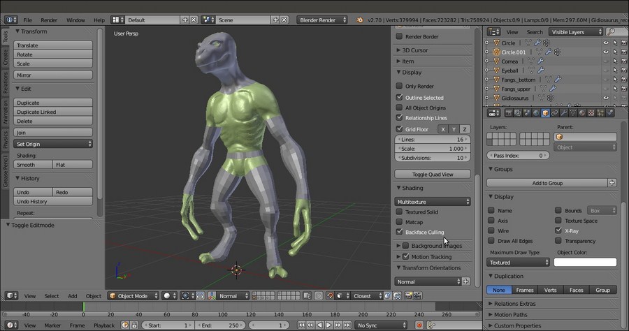
Arms and legs re-topologized
Do the same for the body: just a couple of edge-loops placed at the waist to extrude the geometry from; remember that the chest is covered with the armor breastplate, so only the exposed area needs to be re-topologized.
One Mirror and one Subdivision Surface modifier has been assigned to the three objects (head/neck, arm, and hips/leg). Also, because of the Mirror modifier, the vertices of the half side of the abdomen's edge-loops have been deleted.
After the main parts have been re-topologized, we can start to tweak the position of the vertices on the arm and leg, to better fit the flow and shapes of the muscles and tendons in the sculpted mesh.
Thanks to the aid of the Shrinkwrap modifier, we can do it quite freely; however, before we start with the tweaking, we require a little bit of preparation for a better visibility of the working objects, to affect and modify the new geometry (visible as a wireframe) and have the underlying sculpted mesh visible at the same time.
To do this, we have two ways:
- Go to the Shrinkwrap modifier panel and set the Offset value to 0.002.
- Go to the Object window and disable the X-Ray item; in the Maximum Draw Type slot, under the Display subpanel, select Wire:

The mesh visualized in wireframe mode
- Go to the Shrinkwrap modifier and set the Offset value back to 0.000.
- If this is the case, go to the Object window and, under the Display subpanel, enable the X-Ray item. In the Maximum Draw Type slot, under the Display subpanel, select Textured.
- Go to the Properties 3D view sidepanel (press N if not already present); if necessary, enter Edit Mode and under the Shading subpanel, check the Hidden Wire item.
- In both ways (I used the second one), if you want to enable the Display modifier in Edit mode and Adjust edit cage to modifier result buttons for the Subdivision Surface modifier to see its effect in Edit Mode, it is better to move the Shrinkwrap modifier after the Subdivision Surface modifier in the stack, to have a better looking result.

The second wireframe visualization method
We can now start to add the missing parts, by extruding and moving the vertices to better fit the sculpted features and also adding, if necessary, new edge-loops to better define these features:
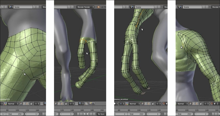
Refining and completing the remaining features
After the wireframe setup, it's easy to tweak the low resolution geometry to better fit the character's anatomy:
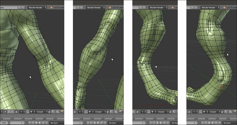
The character's anatomy
The still missing parts are modeled at this stage, such as the inside of the nostrils or the eyelids, again with the aid of the Shrinkwrap modifier; this time, targeted to the Cornea object to project the eyelids geometry onto it with an Offset value of 0.0035:
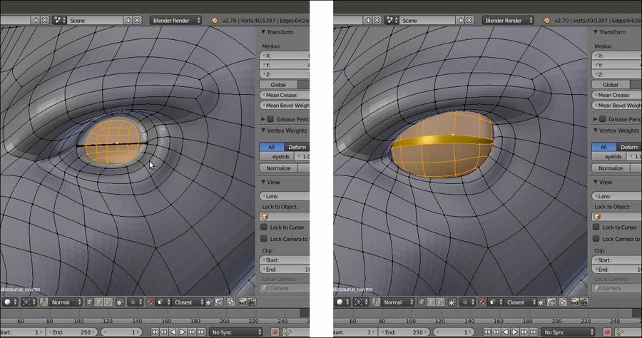
The character's eyelids
Also, we built the inner mouth and the tongue of our character and refined the dental alveoli:
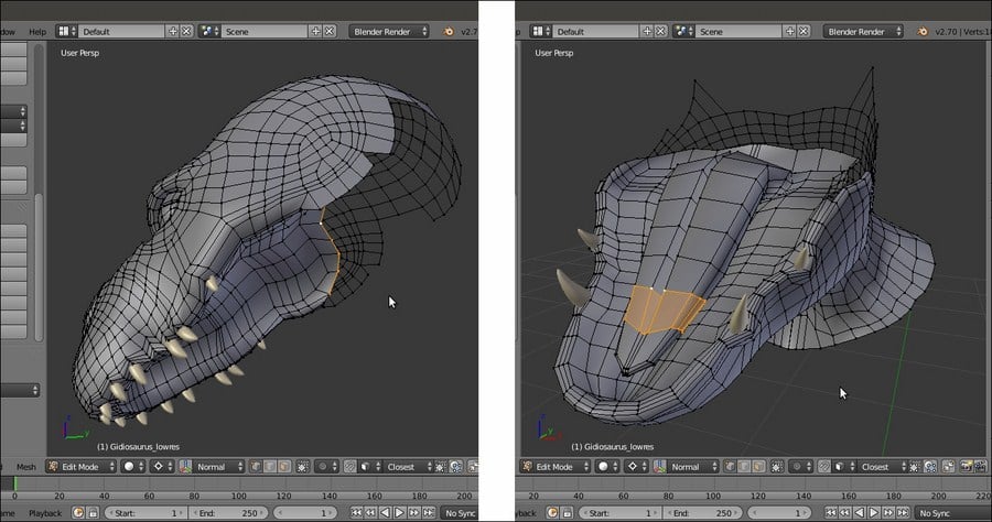
The character's alveoli and tongue
As in every project, we can go on with the refining, adding edge-loops, and so on, and this would seem a never-ending work; instead, at this point, we can consider the Gidiosaurus re-topology at the end, so it's time to apply the Shrinkwrap modifiers and, if this is the case, select the Gidiosaurus body's still separated objects and join them together to have a single mesh.
It's time to do the same with the armor that is still waiting on the 13th scene layer:
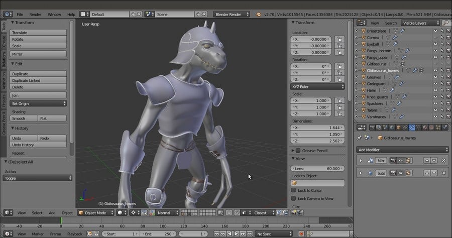
The totally completed re-topologized character with the armor
First, we have to quickly build the geometry using the Shrinkwrap modifier technique and then set the visibility of this geometry to wireframe (Wire), to make the underlying sculpted mesh visible.
The Shrinkwrap modifier, in the first case with the Offset value set high enough to allow the wireframe visibility over the sculpted surface, ensured that all the moved vertices and the new added geometry are automatically wrapped around the target mesh to preserve the volume.
At the end, we took back the Offset value to 0.000 anyway and we applied the Shrinkwrap modifier; then, we joined the re-topologized arm and leg objects together to the Gidiosaurus_lowres one.
As you have probably noticed, we haven't applied the Mirror modifiers yet. This is because it will still be useful in the next chapter.
Getting ready
If necessary, repeat the steps to set up the Shrinkwrap modifier technique:
- Assign the Shrinkwrap modifier to the Gidiosaurus_lowres mesh and in the modifier stack, move it before the Subdivision Surface modifier.
- Click on the Target field to select the Gidiosaurus mesh item and leave Mode to Nearest Surface Point.
- Enable the Display modifier in Edit mode and Adjust edit cage to modifier result buttons and the Keep Above Surface item.
- In Edit Mode, to make the low resolution mesh more easily visible against the high resolution one, change the Offset value to 0.001.
- Having the X-Ray item still active, go to the Shading subpanel under the Properties 3D view sidepanel and check the Backface Culling item.
- Then, to conclude the re-topology, we also need to enable the Copy Attributes Menu add-on; go to Blender User Preferences | Addons | 3D View | 3D View: Copy Attributes Menu.
Let's go on by building the geometry of the neck:
- While still in Edit Mode, just select the head's last edge loop on the neck and extrude it (E key) towards the shoulders.
- Press the Ctrl + R keys and add at least 7 or 8 widthwise edge-loops:
Extruding the neck
- Also, with the aid of the Snap tool, tweak the position of the bottom row of vertices, extrude them to add an edge-loop of faces, and tweak again. Go out of Edit Mode.
The re-topology of the neck
We can use the same technique as in steps 1, 2, and 3 to quickly re-topologize the left arm and leg of the character. Instead of extruding the new geometry from the Gidiosaurus_lowres mesh, in this case, it's better to add a new simple primitive: a Circle or also a Plane; whatever the primitive, when you add it, be sure that the 3D Cursor is at the character's origin pivot point.
As you can see in the following screenshot, at first we just created the geometry only for the main cylindrical sections of the limbs:
Arms and legs re-topologized
Do the same for the body: just a couple of edge-loops placed at the waist to extrude the geometry from; remember that the chest is covered with the armor breastplate, so only the exposed area needs to be re-topologized.
One Mirror and one Subdivision Surface modifier has been assigned to the three objects (head/neck, arm, and hips/leg). Also, because of the Mirror modifier, the vertices of the half side of the abdomen's edge-loops have been deleted.
After the main parts have been re-topologized, we can start to tweak the position of the vertices on the arm and leg, to better fit the flow and shapes of the muscles and tendons in the sculpted mesh.
Thanks to the aid of the Shrinkwrap modifier, we can do it quite freely; however, before we start with the tweaking, we require a little bit of preparation for a better visibility of the working objects, to affect and modify the new geometry (visible as a wireframe) and have the underlying sculpted mesh visible at the same time.
To do this, we have two ways:
- Go to the Shrinkwrap modifier panel and set the Offset value to 0.002.
- Go to the Object window and disable the X-Ray item; in the Maximum Draw Type slot, under the Display subpanel, select Wire:
The mesh visualized in wireframe mode
- Go to the Shrinkwrap modifier and set the Offset value back to 0.000.
- If this is the case, go to the Object window and, under the Display subpanel, enable the X-Ray item. In the Maximum Draw Type slot, under the Display subpanel, select Textured.
- Go to the Properties 3D view sidepanel (press N if not already present); if necessary, enter Edit Mode and under the Shading subpanel, check the Hidden Wire item.
- In both ways (I used the second one), if you want to enable the Display modifier in Edit mode and Adjust edit cage to modifier result buttons for the Subdivision Surface modifier to see its effect in Edit Mode, it is better to move the Shrinkwrap modifier after the Subdivision Surface modifier in the stack, to have a better looking result.
The second wireframe visualization method
We can now start to add the missing parts, by extruding and moving the vertices to better fit the sculpted features and also adding, if necessary, new edge-loops to better define these features:
Refining and completing the remaining features
After the wireframe setup, it's easy to tweak the low resolution geometry to better fit the character's anatomy:
The character's anatomy
The still missing parts are modeled at this stage, such as the inside of the nostrils or the eyelids, again with the aid of the Shrinkwrap modifier; this time, targeted to the Cornea object to project the eyelids geometry onto it with an Offset value of 0.0035:
The character's eyelids
Also, we built the inner mouth and the tongue of our character and refined the dental alveoli:
The character's alveoli and tongue
As in every project, we can go on with the refining, adding edge-loops, and so on, and this would seem a never-ending work; instead, at this point, we can consider the Gidiosaurus re-topology at the end, so it's time to apply the Shrinkwrap modifiers and, if this is the case, select the Gidiosaurus body's still separated objects and join them together to have a single mesh.
It's time to do the same with the armor that is still waiting on the 13th scene layer:
The totally completed re-topologized character with the armor
First, we have to quickly build the geometry using the Shrinkwrap modifier technique and then set the visibility of this geometry to wireframe (Wire), to make the underlying sculpted mesh visible.
The Shrinkwrap modifier, in the first case with the Offset value set high enough to allow the wireframe visibility over the sculpted surface, ensured that all the moved vertices and the new added geometry are automatically wrapped around the target mesh to preserve the volume.
At the end, we took back the Offset value to 0.000 anyway and we applied the Shrinkwrap modifier; then, we joined the re-topologized arm and leg objects together to the Gidiosaurus_lowres one.
As you have probably noticed, we haven't applied the Mirror modifiers yet. This is because it will still be useful in the next chapter.
How to do it…
Let's go on by building the geometry of the neck:
- While still in Edit Mode, just select the head's last edge loop on the neck and extrude it (E key) towards the shoulders.
- Press the Ctrl + R keys and add at least 7 or 8 widthwise edge-loops:
Extruding the neck
- Also, with the aid of the Snap tool, tweak the position of the bottom row of vertices, extrude them to add an edge-loop of faces, and tweak again. Go out of Edit Mode.
The re-topology of the neck
We can use the same technique as in steps 1, 2, and 3 to quickly re-topologize the left arm and leg of the character. Instead of extruding the new geometry from the Gidiosaurus_lowres mesh, in this case, it's better to add a new simple primitive: a Circle or also a Plane; whatever the primitive, when you add it, be sure that the 3D Cursor is at the character's origin pivot point.
As you can see in the following screenshot, at first we just created the geometry only for the main cylindrical sections of the limbs:
Arms and legs re-topologized
Do the same for the body: just a couple of edge-loops placed at the waist to extrude the geometry from; remember that the chest is covered with the armor breastplate, so only the exposed area needs to be re-topologized.
One Mirror and one Subdivision Surface modifier has been assigned to the three objects (head/neck, arm, and hips/leg). Also, because of the Mirror modifier, the vertices of the half side of the abdomen's edge-loops have been deleted.
After the main parts have been re-topologized, we can start to tweak the position of the vertices on the arm and leg, to better fit the flow and shapes of the muscles and tendons in the sculpted mesh.
Thanks to the aid of the Shrinkwrap modifier, we can do it quite freely; however, before we start with the tweaking, we require a little bit of preparation for a better visibility of the working objects, to affect and modify the new geometry (visible as a wireframe) and have the underlying sculpted mesh visible at the same time.
To do this, we have two ways:
- Go to the Shrinkwrap modifier panel and set the Offset value to 0.002.
- Go to the Object window and disable the X-Ray item; in the Maximum Draw Type slot, under the Display subpanel, select Wire:
The mesh visualized in wireframe mode
- Go to the Shrinkwrap modifier and set the Offset value back to 0.000.
- If this is the case, go to the Object window and, under the Display subpanel, enable the X-Ray item. In the Maximum Draw Type slot, under the Display subpanel, select Textured.
- Go to the Properties 3D view sidepanel (press N if not already present); if necessary, enter Edit Mode and under the Shading subpanel, check the Hidden Wire item.
- In both ways (I used the second one), if you want to enable the Display modifier in Edit mode and Adjust edit cage to modifier result buttons for the Subdivision Surface modifier to see its effect in Edit Mode, it is better to move the Shrinkwrap modifier after the Subdivision Surface modifier in the stack, to have a better looking result.
The second wireframe visualization method
We can now start to add the missing parts, by extruding and moving the vertices to better fit the sculpted features and also adding, if necessary, new edge-loops to better define these features:
Refining and completing the remaining features
After the wireframe setup, it's easy to tweak the low resolution geometry to better fit the character's anatomy:
The character's anatomy
The still missing parts are modeled at this stage, such as the inside of the nostrils or the eyelids, again with the aid of the Shrinkwrap modifier; this time, targeted to the Cornea object to project the eyelids geometry onto it with an Offset value of 0.0035:
The character's eyelids
Also, we built the inner mouth and the tongue of our character and refined the dental alveoli:
The character's alveoli and tongue
As in every project, we can go on with the refining, adding edge-loops, and so on, and this would seem a never-ending work; instead, at this point, we can consider the Gidiosaurus re-topology at the end, so it's time to apply the Shrinkwrap modifiers and, if this is the case, select the Gidiosaurus body's still separated objects and join them together to have a single mesh.
It's time to do the same with the armor that is still waiting on the 13th scene layer:
The totally completed re-topologized character with the armor
First, we have to quickly build the geometry using the Shrinkwrap modifier technique and then set the visibility of this geometry to wireframe (Wire), to make the underlying sculpted mesh visible.
The Shrinkwrap modifier, in the first case with the Offset value set high enough to allow the wireframe visibility over the sculpted surface, ensured that all the moved vertices and the new added geometry are automatically wrapped around the target mesh to preserve the volume.
At the end, we took back the Offset value to 0.000 anyway and we applied the Shrinkwrap modifier; then, we joined the re-topologized arm and leg objects together to the Gidiosaurus_lowres one.
As you have probably noticed, we haven't applied the Mirror modifiers yet. This is because it will still be useful in the next chapter.
There's more…
After the main parts have been re-topologized, we can start to tweak the position of the vertices on the arm and leg, to better fit the flow and shapes of the muscles and tendons in the sculpted mesh.
Thanks to the aid of the Shrinkwrap modifier, we can do it quite freely; however, before we start with the tweaking, we require a little bit of preparation for a better visibility of the working objects, to affect and modify the new geometry (visible as a wireframe) and have the underlying sculpted mesh visible at the same time.
To do this, we have two ways:
- Go to the Shrinkwrap modifier panel and set the Offset value to 0.002.
- Go to the Object window and disable the X-Ray item; in the Maximum Draw Type slot, under the Display subpanel, select Wire:
The mesh visualized in wireframe mode
- Go to the Shrinkwrap modifier and set the Offset value back to 0.000.
- If this is the case, go to the Object window and, under the Display subpanel, enable the X-Ray item. In the Maximum Draw Type slot, under the Display subpanel, select Textured.
- Go to the Properties 3D view sidepanel (press N if not already present); if necessary, enter Edit Mode and under the Shading subpanel, check the Hidden Wire item.
- In both ways (I used the second one), if you want to enable the Display modifier in Edit mode and Adjust edit cage to modifier result buttons for the Subdivision Surface modifier to see its effect in Edit Mode, it is better to move the Shrinkwrap modifier after the Subdivision Surface modifier in the stack, to have a better looking result.
The second wireframe visualization method
We can now start to add the missing parts, by extruding and moving the vertices to better fit the sculpted features and also adding, if necessary, new edge-loops to better define these features:
Refining and completing the remaining features
After the wireframe setup, it's easy to tweak the low resolution geometry to better fit the character's anatomy:
The character's anatomy
The still missing parts are modeled at this stage, such as the inside of the nostrils or the eyelids, again with the aid of the Shrinkwrap modifier; this time, targeted to the Cornea object to project the eyelids geometry onto it with an Offset value of 0.0035:
The character's eyelids
Also, we built the inner mouth and the tongue of our character and refined the dental alveoli:
The character's alveoli and tongue
As in every project, we can go on with the refining, adding edge-loops, and so on, and this would seem a never-ending work; instead, at this point, we can consider the Gidiosaurus re-topology at the end, so it's time to apply the Shrinkwrap modifiers and, if this is the case, select the Gidiosaurus body's still separated objects and join them together to have a single mesh.
It's time to do the same with the armor that is still waiting on the 13th scene layer:
The totally completed re-topologized character with the armor
First, we have to quickly build the geometry using the Shrinkwrap modifier technique and then set the visibility of this geometry to wireframe (Wire), to make the underlying sculpted mesh visible.
The Shrinkwrap modifier, in the first case with the Offset value set high enough to allow the wireframe visibility over the sculpted surface, ensured that all the moved vertices and the new added geometry are automatically wrapped around the target mesh to preserve the volume.
At the end, we took back the Offset value to 0.000 anyway and we applied the Shrinkwrap modifier; then, we joined the re-topologized arm and leg objects together to the Gidiosaurus_lowres one.
As you have probably noticed, we haven't applied the Mirror modifiers yet. This is because it will still be useful in the next chapter.
How it works…
First, we have to quickly build the geometry using the Shrinkwrap modifier technique and then set the visibility of this geometry to wireframe (Wire), to make the underlying sculpted mesh visible.
The Shrinkwrap modifier, in the first case with the Offset value set high enough to allow the wireframe visibility over the sculpted surface, ensured that all the moved vertices and the new added geometry are automatically wrapped around the target mesh to preserve the volume.
At the end, we took back the Offset value to 0.000 anyway and we applied the Shrinkwrap modifier; then, we joined the re-topologized arm and leg objects together to the Gidiosaurus_lowres one.
As you have probably noticed, we haven't applied the Mirror modifiers yet. This is because it will still be useful in the next chapter.
In this chapter, we will cover the following recipes:
- Preparing the low resolution mesh for unwrapping
- UV unwrapping the mesh
- Editing the UV islands
- Using the Smart UV Project tool
- Modifying the mesh and the UV islands
- Setting up additional UV layers
- Exporting the UV Map layout
So, at this point, we have sculpted our high resolution character and through the retopology process, we have obtained a low resolution copy, which is easier to use for rigging, texturing, and animation.
There are several ways to apply textures to a mesh in Blender, as in any other 3D package. In our case, we are going to use UV Mapping, which is certainly one of the most commonly used and efficient methods for organic shapes.
Before the unwrapping process, the mesh must be prepared to make the task easier.
In this recipe, we'll fix the last details such as the position of some of the character's parts (for instance, the closed mouth) and in general, anything that is needed to facilitate the unwrapping.
To be more precise, before the unwrapping, we must perform the following tasks in the right order:
- Join the teeth and talons to the body.
- Create the vertex group for the mandible.
- Open the mouth.
- Mark the seams to unwrap the body.
So, open the Gidiosaurus_retopology.blend file and deactivate the layer with the armor to hide it; select the
Gidiosaurus object and save the file as Gidiosaurus_unwrap.blend.
The simplest of the four tasks just so happens to be the first, joining the body with the teeth and talons.
To join the body parts, follow these steps:
- Select the Talons item in the Outliner, and then hold Shift and select the Fangs_bottom, Fangs_upper, and Gidiosaurus_lowres items.
- Press Ctrl + J to join them.
- Right away we will notice that, because the retopologized mesh didn't have any material assigned, the whole object gets the only material available, which is the
Enamelmaterial we had assigned to the talons and teeth earlier. - To fix this, assign a new material, or you can also assign the already existing
Bodymaterial, to the retopologized mesh before the joining operation. - Alternatively, after the joining, click on the + icon to the side of the material names, and then select the New button in the Material window to create a new material. Now, enter Edit Mode, put the mouse pointer on the Gidiosaurus mesh, and press the L key to select all the connected vertices. Because the talons and teeth vertices are joined, but not connected to the face vertices, they don't get selected; for the same reason, you have to repeat the operation three times to select the head, arm, hips, and leg vertices:

The head, arm and hip/leg vertices selected in Edit Mode
- Click on the Assign button and go out of the Edit Mode. Now, edit the name and color of the new material or whatever, or else switch it with the
Bodyone.The second task is a bit more complex and is covered in more detail in Chapter 7, Skinning the Low Resolution Mesh, which is about the skinning process. However, we need to explore this subject a little bit now, as it will help us operate on a small portion of the mesh easily.
To create a vertex group to open the mouth, follow these steps:
- Go to the Side view and zoom in on the head of the character.
- Go to the Object Data window; under the Vertex Groups subpanel, add a new group and rename it
mand(short for mandible). - Press Ctrl + Tab to go into Weight Paint mode (or left-click on the mode button on the 3D window toolbar to switch from Edit Mode to Weight Paint mode); press Z to go into Wireframe viewport shading mode so that you can see the edges of the topology.
- By using a combination of vertex selection mode, both in Edit Mode and by painting with Weight and Strength as 1.000 in the Weight Paint mode, assign vertices to the group of the mandible area and the part of the neck; obviously, you have to include the vertices of the inner bottom jaw, as well as the tongue and bottom teeth:

The visualization of the mand vertex group
- Press Ctrl + Tab to exit the Weight Paint mode.
Note that a vertex group can be edited at a later time, so it will be easier to set the exact amount of weight on the vertices by looking at the Lattice modifier feedback, which is the next step.
So, to open the mouth, perform the following steps:
- Add an Empty object to the center of the scene (Shift + A | Empty | Plain Axes).
- Go to the Side view (press the 3 key on the numpad). Move the Empty to the position where the mandible should join the skull (to be precise, I placed it at this location: X = 0.0000, Y = -0.3206, and Z = 2.2644; go to the Properties 3D view sidepanel, and under the Transform subpanel, enter the values in the first three slots under the Location item).
- To ensure that the Empty cannot be moved anymore, click on the lock icon on the right-hand side of its slot in the Outliner and also rename it to
Empty_rot_mand:
The Empty_rot_mand in place
- With the Empty still selected, press Shift + S | Cursor to Selected.
- Add a Lattice object to the scene (Shift + A | Lattice), and in the Object Data window, set Interpolation Type for U, V, and W to Linear; select the Gidiosaurus object and go to the Objects Modifier window; assign a Lattice modifier. Move it before the Subdivision Surface modifier.
- In the Object field, select the Lattice item; in the Vertex Group field, select the mand item.
- In the Side view, select the Lattice object, go into Edit Mode, and select all the vertices and rotate them 35 degrees counterclockwise around the x axis:

Rotating the Lattice to open the mouth
As you can see, the Lattice only affects the vertices inside the mand vertex group; however, there is a clear indentation on the throat where the mand vertex group ends abruptly, so now we must blur this boundary to keep the smooth curved transition from the bottom jaw to the neck, and remove the abrupt edge.
- Go back into the Weight Paint mode (Ctrl + Tab) and click on the Brush icon at the top of the Tools tab to switch the Draw brush with the Blur brush, and then start to blur the boundaries of the mand vertex group.
- Sometimes, blurring the edge weights is not enough, so go back to the Draw brush, set the Strength to 0.500 (or whatever value you find works best), and paint on the vertices; then refine the transition again with the Blur brush:

Blurring and painting the weights
- To make the job easier and faster, you can temporarily disable the Lattice modifier, as well as the Subdivision Surface modifier.
- When you are done, go out of the Weight Paint mode, apply the Lattice modifier, and delete the Lattice object.
- Make sure to keep the Empty_rot_mand, which that will turn out to be useful when rigging the character. For now, just hide or move it onto a different layer.
At this point, we can obviously edit the throat area vertices as usual: relaxing and tweaking them and so on. Actually, this is the right moment to tweak all the vertices and any areas that couldn't be done before, such as the inside of the mouth, the inner cheeks, and so forth, because now we are going to do the last preparation task before the unwrapping.
To mark seams for the unwrapping of the body, we have to perform the following steps. Because our low resolution mesh is actually still only one half side, we don't need to place seams as median cuts, we only need to divide different areas (for example, the inside of the mouth from the outside of the mouth) and unroll cylindrical parts such as the arms, fingers, and teeth:
- Go into Edit Mode and zoom in to the character's head; press Ctrl + Tab to call the Mesh Select Mode pop-up menu and select the Edge item, and then start to select the edge-loop inside the mouth (Alt + right-click to select an edge-loop); start from the bottom jaw, switching direction at the end of the mouth rim to go upward, and finish on the inside of the upper jaw:

The selected edge-loops inside the mouth
- Press Ctrl + E to open the Edges pop-up menu and select the Mark Seam item. Alternatively, click on the Shading / UVs tab in the Tool Shelf, to the left-hand side of the screen, and in the UVs subpanel, click on the Mark Seam button under the UV Mapping item:

Marking the seams
- Repeat the procedure for the arm; try to place the seams in the less visible areas:

The seams on the arm
- Do the same for the pelvis and leg; divide them into two parts with the seams and also try to place the seams inside the natural body folds, if possible:

The seams on the pelvis/leg parts
- It is important to try to place the seams to divide parts that would get unwrapped badly if treated as a single object; for example, the inner nostril and tongue from the inner mouth:

The seams inside the head
- The final seams to add are for the teeth and talons, which would otherwise get badly unwrapped as squares:

The seams of the small parts
- Save the file.
Getting ready
To be more precise, before the unwrapping, we must perform the following tasks in the right order:
- Join the teeth and talons to the body.
- Create the vertex group for the mandible.
- Open the mouth.
- Mark the seams to unwrap the body.
So, open the Gidiosaurus_retopology.blend file and deactivate the layer with the armor to hide it; select the
Gidiosaurus object and save the file as Gidiosaurus_unwrap.blend.
The simplest of the four tasks just so happens to be the first, joining the body with the teeth and talons.
To join the body parts, follow these steps:
- Select the Talons item in the Outliner, and then hold Shift and select the Fangs_bottom, Fangs_upper, and Gidiosaurus_lowres items.
- Press Ctrl + J to join them.
- Right away we will notice that, because the retopologized mesh didn't have any material assigned, the whole object gets the only material available, which is the
Enamelmaterial we had assigned to the talons and teeth earlier. - To fix this, assign a new material, or you can also assign the already existing
Bodymaterial, to the retopologized mesh before the joining operation. - Alternatively, after the joining, click on the + icon to the side of the material names, and then select the New button in the Material window to create a new material. Now, enter Edit Mode, put the mouse pointer on the Gidiosaurus mesh, and press the L key to select all the connected vertices. Because the talons and teeth vertices are joined, but not connected to the face vertices, they don't get selected; for the same reason, you have to repeat the operation three times to select the head, arm, hips, and leg vertices:
The head, arm and hip/leg vertices selected in Edit Mode
- Click on the Assign button and go out of the Edit Mode. Now, edit the name and color of the new material or whatever, or else switch it with the
Bodyone.The second task is a bit more complex and is covered in more detail in Chapter 7, Skinning the Low Resolution Mesh, which is about the skinning process. However, we need to explore this subject a little bit now, as it will help us operate on a small portion of the mesh easily.
To create a vertex group to open the mouth, follow these steps:
- Go to the Side view and zoom in on the head of the character.
- Go to the Object Data window; under the Vertex Groups subpanel, add a new group and rename it
mand(short for mandible). - Press Ctrl + Tab to go into Weight Paint mode (or left-click on the mode button on the 3D window toolbar to switch from Edit Mode to Weight Paint mode); press Z to go into Wireframe viewport shading mode so that you can see the edges of the topology.
- By using a combination of vertex selection mode, both in Edit Mode and by painting with Weight and Strength as 1.000 in the Weight Paint mode, assign vertices to the group of the mandible area and the part of the neck; obviously, you have to include the vertices of the inner bottom jaw, as well as the tongue and bottom teeth:
The visualization of the mand vertex group
- Press Ctrl + Tab to exit the Weight Paint mode.
Note that a vertex group can be edited at a later time, so it will be easier to set the exact amount of weight on the vertices by looking at the Lattice modifier feedback, which is the next step.
So, to open the mouth, perform the following steps:
- Add an Empty object to the center of the scene (Shift + A | Empty | Plain Axes).
- Go to the Side view (press the 3 key on the numpad). Move the Empty to the position where the mandible should join the skull (to be precise, I placed it at this location: X = 0.0000, Y = -0.3206, and Z = 2.2644; go to the Properties 3D view sidepanel, and under the Transform subpanel, enter the values in the first three slots under the Location item).
- To ensure that the Empty cannot be moved anymore, click on the lock icon on the right-hand side of its slot in the Outliner and also rename it to
Empty_rot_mand:The Empty_rot_mand in place
- With the Empty still selected, press Shift + S | Cursor to Selected.
- Add a Lattice object to the scene (Shift + A | Lattice), and in the Object Data window, set Interpolation Type for U, V, and W to Linear; select the Gidiosaurus object and go to the Objects Modifier window; assign a Lattice modifier. Move it before the Subdivision Surface modifier.
- In the Object field, select the Lattice item; in the Vertex Group field, select the mand item.
- In the Side view, select the Lattice object, go into Edit Mode, and select all the vertices and rotate them 35 degrees counterclockwise around the x axis:
Rotating the Lattice to open the mouth
As you can see, the Lattice only affects the vertices inside the mand vertex group; however, there is a clear indentation on the throat where the mand vertex group ends abruptly, so now we must blur this boundary to keep the smooth curved transition from the bottom jaw to the neck, and remove the abrupt edge.
- Go back into the Weight Paint mode (Ctrl + Tab) and click on the Brush icon at the top of the Tools tab to switch the Draw brush with the Blur brush, and then start to blur the boundaries of the mand vertex group.
- Sometimes, blurring the edge weights is not enough, so go back to the Draw brush, set the Strength to 0.500 (or whatever value you find works best), and paint on the vertices; then refine the transition again with the Blur brush:
Blurring and painting the weights
- To make the job easier and faster, you can temporarily disable the Lattice modifier, as well as the Subdivision Surface modifier.
- When you are done, go out of the Weight Paint mode, apply the Lattice modifier, and delete the Lattice object.
- Make sure to keep the Empty_rot_mand, which that will turn out to be useful when rigging the character. For now, just hide or move it onto a different layer.
At this point, we can obviously edit the throat area vertices as usual: relaxing and tweaking them and so on. Actually, this is the right moment to tweak all the vertices and any areas that couldn't be done before, such as the inside of the mouth, the inner cheeks, and so forth, because now we are going to do the last preparation task before the unwrapping.
To mark seams for the unwrapping of the body, we have to perform the following steps. Because our low resolution mesh is actually still only one half side, we don't need to place seams as median cuts, we only need to divide different areas (for example, the inside of the mouth from the outside of the mouth) and unroll cylindrical parts such as the arms, fingers, and teeth:
- Go into Edit Mode and zoom in to the character's head; press Ctrl + Tab to call the Mesh Select Mode pop-up menu and select the Edge item, and then start to select the edge-loop inside the mouth (Alt + right-click to select an edge-loop); start from the bottom jaw, switching direction at the end of the mouth rim to go upward, and finish on the inside of the upper jaw:
The selected edge-loops inside the mouth
- Press Ctrl + E to open the Edges pop-up menu and select the Mark Seam item. Alternatively, click on the Shading / UVs tab in the Tool Shelf, to the left-hand side of the screen, and in the UVs subpanel, click on the Mark Seam button under the UV Mapping item:
Marking the seams
- Repeat the procedure for the arm; try to place the seams in the less visible areas:
The seams on the arm
- Do the same for the pelvis and leg; divide them into two parts with the seams and also try to place the seams inside the natural body folds, if possible:
The seams on the pelvis/leg parts
- It is important to try to place the seams to divide parts that would get unwrapped badly if treated as a single object; for example, the inner nostril and tongue from the inner mouth:
The seams inside the head
- The final seams to add are for the teeth and talons, which would otherwise get badly unwrapped as squares:
The seams of the small parts
- Save the file.
How to do it…
The simplest of the four tasks just so happens to be the first, joining the body with the teeth and talons.
To join the body parts, follow these steps:
- Select the Talons item in the Outliner, and then hold Shift and select the Fangs_bottom, Fangs_upper, and Gidiosaurus_lowres items.
- Press Ctrl + J to join them.
- Right away we will notice that, because the retopologized mesh didn't have any material assigned, the whole object gets the only material available, which is the
Enamelmaterial we had assigned to the talons and teeth earlier. - To fix this, assign a new material, or you can also assign the already existing
Bodymaterial, to the retopologized mesh before the joining operation. - Alternatively, after the joining, click on the + icon to the side of the material names, and then select the New button in the Material window to create a new material. Now, enter Edit Mode, put the mouse pointer on the Gidiosaurus mesh, and press the L key to select all the connected vertices. Because the talons and teeth vertices are joined, but not connected to the face vertices, they don't get selected; for the same reason, you have to repeat the operation three times to select the head, arm, hips, and leg vertices:
The head, arm and hip/leg vertices selected in Edit Mode
- Click on the Assign button and go out of the Edit Mode. Now, edit the name and color of the new material or whatever, or else switch it with the
Bodyone.The second task is a bit more complex and is covered in more detail in Chapter 7, Skinning the Low Resolution Mesh, which is about the skinning process. However, we need to explore this subject a little bit now, as it will help us operate on a small portion of the mesh easily.
To create a vertex group to open the mouth, follow these steps:
- Go to the Side view and zoom in on the head of the character.
- Go to the Object Data window; under the Vertex Groups subpanel, add a new group and rename it
mand(short for mandible). - Press Ctrl + Tab to go into Weight Paint mode (or left-click on the mode button on the 3D window toolbar to switch from Edit Mode to Weight Paint mode); press Z to go into Wireframe viewport shading mode so that you can see the edges of the topology.
- By using a combination of vertex selection mode, both in Edit Mode and by painting with Weight and Strength as 1.000 in the Weight Paint mode, assign vertices to the group of the mandible area and the part of the neck; obviously, you have to include the vertices of the inner bottom jaw, as well as the tongue and bottom teeth:
The visualization of the mand vertex group
- Press Ctrl + Tab to exit the Weight Paint mode.
Note that a vertex group can be edited at a later time, so it will be easier to set the exact amount of weight on the vertices by looking at the Lattice modifier feedback, which is the next step.
So, to open the mouth, perform the following steps:
- Add an Empty object to the center of the scene (Shift + A | Empty | Plain Axes).
- Go to the Side view (press the 3 key on the numpad). Move the Empty to the position where the mandible should join the skull (to be precise, I placed it at this location: X = 0.0000, Y = -0.3206, and Z = 2.2644; go to the Properties 3D view sidepanel, and under the Transform subpanel, enter the values in the first three slots under the Location item).
- To ensure that the Empty cannot be moved anymore, click on the lock icon on the right-hand side of its slot in the Outliner and also rename it to
Empty_rot_mand:The Empty_rot_mand in place
- With the Empty still selected, press Shift + S | Cursor to Selected.
- Add a Lattice object to the scene (Shift + A | Lattice), and in the Object Data window, set Interpolation Type for U, V, and W to Linear; select the Gidiosaurus object and go to the Objects Modifier window; assign a Lattice modifier. Move it before the Subdivision Surface modifier.
- In the Object field, select the Lattice item; in the Vertex Group field, select the mand item.
- In the Side view, select the Lattice object, go into Edit Mode, and select all the vertices and rotate them 35 degrees counterclockwise around the x axis:
Rotating the Lattice to open the mouth
As you can see, the Lattice only affects the vertices inside the mand vertex group; however, there is a clear indentation on the throat where the mand vertex group ends abruptly, so now we must blur this boundary to keep the smooth curved transition from the bottom jaw to the neck, and remove the abrupt edge.
- Go back into the Weight Paint mode (Ctrl + Tab) and click on the Brush icon at the top of the Tools tab to switch the Draw brush with the Blur brush, and then start to blur the boundaries of the mand vertex group.
- Sometimes, blurring the edge weights is not enough, so go back to the Draw brush, set the Strength to 0.500 (or whatever value you find works best), and paint on the vertices; then refine the transition again with the Blur brush:
Blurring and painting the weights
- To make the job easier and faster, you can temporarily disable the Lattice modifier, as well as the Subdivision Surface modifier.
- When you are done, go out of the Weight Paint mode, apply the Lattice modifier, and delete the Lattice object.
- Make sure to keep the Empty_rot_mand, which that will turn out to be useful when rigging the character. For now, just hide or move it onto a different layer.
At this point, we can obviously edit the throat area vertices as usual: relaxing and tweaking them and so on. Actually, this is the right moment to tweak all the vertices and any areas that couldn't be done before, such as the inside of the mouth, the inner cheeks, and so forth, because now we are going to do the last preparation task before the unwrapping.
To mark seams for the unwrapping of the body, we have to perform the following steps. Because our low resolution mesh is actually still only one half side, we don't need to place seams as median cuts, we only need to divide different areas (for example, the inside of the mouth from the outside of the mouth) and unroll cylindrical parts such as the arms, fingers, and teeth:
- Go into Edit Mode and zoom in to the character's head; press Ctrl + Tab to call the Mesh Select Mode pop-up menu and select the Edge item, and then start to select the edge-loop inside the mouth (Alt + right-click to select an edge-loop); start from the bottom jaw, switching direction at the end of the mouth rim to go upward, and finish on the inside of the upper jaw:
The selected edge-loops inside the mouth
- Press Ctrl + E to open the Edges pop-up menu and select the Mark Seam item. Alternatively, click on the Shading / UVs tab in the Tool Shelf, to the left-hand side of the screen, and in the UVs subpanel, click on the Mark Seam button under the UV Mapping item:
Marking the seams
- Repeat the procedure for the arm; try to place the seams in the less visible areas:
The seams on the arm
- Do the same for the pelvis and leg; divide them into two parts with the seams and also try to place the seams inside the natural body folds, if possible:
The seams on the pelvis/leg parts
- It is important to try to place the seams to divide parts that would get unwrapped badly if treated as a single object; for example, the inner nostril and tongue from the inner mouth:
The seams inside the head
- The final seams to add are for the teeth and talons, which would otherwise get badly unwrapped as squares:
The seams of the small parts
- Save the file.
At this point, everything is ready for the unwrapping.
Put the mouse pointer on the bottom or on the top horizontal borders of the 3D window. As the mouse pointer changes to a double-arrow icon, right-click and in the Area Options pop-up menu select the Split Area item; then, left-click to obtain two windows and switch the left one to UV/Image Editor.

The two windows
To unwrap the mesh in Blender, several options are available; however, the one we are going to use now is the basic unwrap, the result of which we will edit and refine later:
- Ensure that the UV/Image Editor window is not set to Render Result, otherwise it won't display the UV islands.
- Select the Gidiosaurus_lowres object and enter Edit Mode. Select all the vertices (A key) and press the U key; in the UV Mapping pop-up menu, select the first item, Unwrap:

Unwrapping the mesh
After a while, the UV layer of the unwrapped mesh appears in the UV/Image Editor window; as you can see, several things can be improved. Moreover, we are still using only half of a mesh.
- Go out of the Edit Mode and go to the Object Modifiers window; apply the Mirror modifier.
- Go back into Edit Mode and press 1 on the numpad to go to the Front view; press Ctrl + R and place a median seam through the head part of the mesh, as well as through the pelvis part:

A new loop cut
- Press Ctrl + Tab to switch to vertex selection and press Z to go into the Wireframe viewport shading mode, and then box-select the vertices on the left-hand side of the mesh (which is the side created by the Mirror modifier).
- Go to the UV/Image Editor window; if not already selected, press A to select all the UV islands of the UV layer, and then press Ctrl + M | X | Enter to mirror these selected islands.
- Press G to move them (temporarily) outside the default U0/V0 tile space, as shown in the following screenshot:

The selected half body vertices and the corresponding UV islands outside the U0/V0 tile space
- Go to the 3D view and press A twice to select all the vertices; go to the UV/Image Editor window and press Ctrl + A to average the size of all the islands reciprocally.
- Select all the islands and press Ctrl + P to automatically pack all of them inside the UV tile.
- If you are not satisfied with the result of the Pack islands tool, adjust the position (G key), rotation (R key), and scale (S key) of the islands; group together the similar ones (for example, the teeth, talons, arms, and so on), but try to place them to fill the image tile space as much as possible. To select one island, just put the mouse over it and press L, and Shift + L to multiselect. Use the X and Y keys to constrain the movements of the islands on the corresponding axis:

Adjusting the UV islands' position
- When you are done, ensure that all the vertices of all the islands in the UV/Image Editor window are selected, and click on the New button on the toolbar of the UV/Image Editor window; in the New Image pop-up panel, set Width and Height to 3072 pixels, and Generated Type should be set to UV Grid. Then, click on the OK button to confirm.
- Go to the 3D window and press Z to go in the Solid viewport shading mode. Then, go to the Properties 3D view sidepanel and under the Shading subpanel, check the Textured Solid item.
- Go out of the Edit Mode and save the file:

Assigning a grid image to the unwrapped UV islands
This should be enough; even if the halves of the mesh are disconnected, Blender can perfectly solve the mesh painting without visible seams.
However, if we look at the character shown in the Textured Solid mode in the 3D view, it's clear that the unwrap of some part of the mesh could be better; for example, you can see a difference in the size of the mapped grid in the head/neck area, inside the mouth, and on the arms and legs (look at the arrows in the following images):
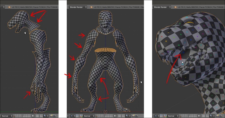
Differences in the mapped grid image
Although this is not a very big issue, the unwrap can be refined further to avoid distortions as much as possible, as well as potential future problems when we'll paint the character textures; we are going to see this in the next recipe.
Getting ready
Put the mouse pointer on the bottom or on the top horizontal borders of the 3D window. As the mouse pointer changes to a double-arrow icon, right-click and in the Area Options pop-up menu select the Split Area item; then, left-click to obtain two windows and switch the left one to UV/Image Editor.
The two windows
To unwrap the mesh in Blender, several options are available; however, the one we are going to use now is the basic unwrap, the result of which we will edit and refine later:
- Ensure that the UV/Image Editor window is not set to Render Result, otherwise it won't display the UV islands.
- Select the Gidiosaurus_lowres object and enter Edit Mode. Select all the vertices (A key) and press the U key; in the UV Mapping pop-up menu, select the first item, Unwrap:
Unwrapping the mesh
After a while, the UV layer of the unwrapped mesh appears in the UV/Image Editor window; as you can see, several things can be improved. Moreover, we are still using only half of a mesh.
- Go out of the Edit Mode and go to the Object Modifiers window; apply the Mirror modifier.
- Go back into Edit Mode and press 1 on the numpad to go to the Front view; press Ctrl + R and place a median seam through the head part of the mesh, as well as through the pelvis part:
A new loop cut
- Press Ctrl + Tab to switch to vertex selection and press Z to go into the Wireframe viewport shading mode, and then box-select the vertices on the left-hand side of the mesh (which is the side created by the Mirror modifier).
- Go to the UV/Image Editor window; if not already selected, press A to select all the UV islands of the UV layer, and then press Ctrl + M | X | Enter to mirror these selected islands.
- Press G to move them (temporarily) outside the default U0/V0 tile space, as shown in the following screenshot:
The selected half body vertices and the corresponding UV islands outside the U0/V0 tile space
- Go to the 3D view and press A twice to select all the vertices; go to the UV/Image Editor window and press Ctrl + A to average the size of all the islands reciprocally.
- Select all the islands and press Ctrl + P to automatically pack all of them inside the UV tile.
- If you are not satisfied with the result of the Pack islands tool, adjust the position (G key), rotation (R key), and scale (S key) of the islands; group together the similar ones (for example, the teeth, talons, arms, and so on), but try to place them to fill the image tile space as much as possible. To select one island, just put the mouse over it and press L, and Shift + L to multiselect. Use the X and Y keys to constrain the movements of the islands on the corresponding axis:
Adjusting the UV islands' position
- When you are done, ensure that all the vertices of all the islands in the UV/Image Editor window are selected, and click on the New button on the toolbar of the UV/Image Editor window; in the New Image pop-up panel, set Width and Height to 3072 pixels, and Generated Type should be set to UV Grid. Then, click on the OK button to confirm.
- Go to the 3D window and press Z to go in the Solid viewport shading mode. Then, go to the Properties 3D view sidepanel and under the Shading subpanel, check the Textured Solid item.
- Go out of the Edit Mode and save the file:
Assigning a grid image to the unwrapped UV islands
This should be enough; even if the halves of the mesh are disconnected, Blender can perfectly solve the mesh painting without visible seams.
However, if we look at the character shown in the Textured Solid mode in the 3D view, it's clear that the unwrap of some part of the mesh could be better; for example, you can see a difference in the size of the mapped grid in the head/neck area, inside the mouth, and on the arms and legs (look at the arrows in the following images):
Differences in the mapped grid image
Although this is not a very big issue, the unwrap can be refined further to avoid distortions as much as possible, as well as potential future problems when we'll paint the character textures; we are going to see this in the next recipe.
How to do it…
To unwrap the mesh in Blender, several options are available; however, the one we are going to use now is the basic unwrap, the result of which we will edit and refine later:
- Ensure that the UV/Image Editor window is not set to Render Result, otherwise it won't display the UV islands.
- Select the Gidiosaurus_lowres object and enter Edit Mode. Select all the vertices (A key) and press the U key; in the UV Mapping pop-up menu, select the first item, Unwrap:
Unwrapping the mesh
After a while, the UV layer of the unwrapped mesh appears in the UV/Image Editor window; as you can see, several things can be improved. Moreover, we are still using only half of a mesh.
- Go out of the Edit Mode and go to the Object Modifiers window; apply the Mirror modifier.
- Go back into Edit Mode and press 1 on the numpad to go to the Front view; press Ctrl + R and place a median seam through the head part of the mesh, as well as through the pelvis part:
A new loop cut
- Press Ctrl + Tab to switch to vertex selection and press Z to go into the Wireframe viewport shading mode, and then box-select the vertices on the left-hand side of the mesh (which is the side created by the Mirror modifier).
- Go to the UV/Image Editor window; if not already selected, press A to select all the UV islands of the UV layer, and then press Ctrl + M | X | Enter to mirror these selected islands.
- Press G to move them (temporarily) outside the default U0/V0 tile space, as shown in the following screenshot:
The selected half body vertices and the corresponding UV islands outside the U0/V0 tile space
- Go to the 3D view and press A twice to select all the vertices; go to the UV/Image Editor window and press Ctrl + A to average the size of all the islands reciprocally.
- Select all the islands and press Ctrl + P to automatically pack all of them inside the UV tile.
- If you are not satisfied with the result of the Pack islands tool, adjust the position (G key), rotation (R key), and scale (S key) of the islands; group together the similar ones (for example, the teeth, talons, arms, and so on), but try to place them to fill the image tile space as much as possible. To select one island, just put the mouse over it and press L, and Shift + L to multiselect. Use the X and Y keys to constrain the movements of the islands on the corresponding axis:
Adjusting the UV islands' position
- When you are done, ensure that all the vertices of all the islands in the UV/Image Editor window are selected, and click on the New button on the toolbar of the UV/Image Editor window; in the New Image pop-up panel, set Width and Height to 3072 pixels, and Generated Type should be set to UV Grid. Then, click on the OK button to confirm.
- Go to the 3D window and press Z to go in the Solid viewport shading mode. Then, go to the Properties 3D view sidepanel and under the Shading subpanel, check the Textured Solid item.
- Go out of the Edit Mode and save the file:
Assigning a grid image to the unwrapped UV islands
This should be enough; even if the halves of the mesh are disconnected, Blender can perfectly solve the mesh painting without visible seams.
However, if we look at the character shown in the Textured Solid mode in the 3D view, it's clear that the unwrap of some part of the mesh could be better; for example, you can see a difference in the size of the mapped grid in the head/neck area, inside the mouth, and on the arms and legs (look at the arrows in the following images):
Differences in the mapped grid image
Although this is not a very big issue, the unwrap can be refined further to avoid distortions as much as possible, as well as potential future problems when we'll paint the character textures; we are going to see this in the next recipe.
We are now going to join the two UV islands' halves together, in order to improve the final look of the texturing; we are also going to modify, if possible, a little of the island proportions in order to obtain a more regular flow of the UV vertices, and fix the distortions we have seen in the last image of the previous recipe.
We are going to the use the pin tool, which is normally used in conjunction with the Live Unwrap tool.
First, we'll try to recalculate the unwrap of some of the islands by modifying the seams of the mesh.
Before we start though, let's see if we can improve some of the visibility of the UV islands in the UV/Image Editor:
- Put the mouse cursor in the UV/Image Editor window and press the N key.
- In the Properties sidepanel that appears by pressing the N key on the right-hand side of the window, go to the Display subpanel and click on the Black or White button (depending on your preference) under the UV item. Check also the Smooth item box.
- Also, check the Stretch item, which even though it was made for a different purpose, can increase the visibility of the islands a lot.
- Press N again to get rid of the Properties sidepanel.
All these options enabled should make the islands more easily readable in the UV/Image Editor window:
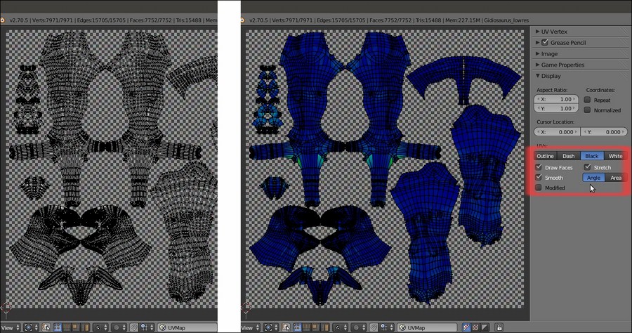
The UV islands made more easily readable by the enabled items
Now we can start with the editing; initially, we are going to freeze the islands that we don't want to modify because their unwrap is either satisfactory, or we will deal with it later. So, perform the following steps:
- Press A to select all the islands, then by putting the mouse pointer on the two pelvis island halves and pressing Shift + L, multi-deselect them; press the P key to pin the remaining selected UV islands and then A to deselect everything:

To the right-hand side, the pinned UV islands
- Zoom in on the islands of the pelvis, select both the left and right outer edge-loops, as shown in the following left image, and press P to pin them.
- Go to the 3D view and clear only the front part of the median seam on the pelvis. To do this, start to clear the seam from the front edges, go down and stop where it crosses the horizontal seam that passes the bottom part of the groin and legs, and leave the back part of the vertical median seam still marked:

Pinning the extreme vertices in the UV/Image Editor, and editing the seam on the mesh
- Go into Face selection mode and select all the faces of the pelvis; put the mouse pointer in the 3D view and press U | Unwrap (alternatively, go into the UV/Image Editor and press E):

Unwrapping again with the pinning and a different seam
The island will keep the previous position because of the pinned edges, and is now unwrapped as one single piece (with the obvious exception of the seam on the back).
- We won't modify the pelvis island any further, so select all its vertices and press P to pin all of them and then deselect them.
- Press A in the 3D view to select all the faces of the mesh and make all the islands visible in the UV/Image Editor. Note that they are all pinned at the moment, so just select the vertices you want to unpin (Alt + P) in the islands of the tongue and inner mouth. Then, clear the median seam in the corresponding pieces on the mesh, and press E again:

Re-unwrapping the tongue and inner mouth areas
- Select the UV vertices of the resulting islands and unpin them all; next, pin just one vertex at the top of the islands and one at the bottom, and unwrap again. This will result in a more organically distributed unwrap of the parts:

Re-unwrapping again with a different pinning
- Select all the faces of the mesh, and then all the islands in the UV/Image Editor window. Press Ctrl + A to average their relative size and adjust their position in the default tile space:

The rearranged UV islands
Now, let's work on the head piece that, as in every character, should be the most important and well-finished piece.
At the moment, the face is made using two separate islands; although this won't be visible in the final textured rendering of our character, it's always better, if possible, to join them in order to have a single piece, especially in the front mesh faces. Due to the elongated snout of the character, if we were to unwrap the head as a single piece simply without the median seam, we wouldn't get a nice evenly mapped result, so we must divide the whole head into more pieces.
Actually, we can take advantage of the fact that the Gidiosaurus is wearing a helmet and that most of the head will be covered by it; this allows us to easily split the face from the rest of the mesh, hiding the seams under the helmet.
- Go into Edge selection mode and mark the seams, dividing the face from the cranium and neck as shown in the following screenshots. Select the crossing edge-loops, and then clear the unnecessary parts:

New seams for the character's head part 1
- Also clear the median seam in the upper face part, and under the seam on the bottom jaw, leaving it only on the front mandible and on the back of the cranium and neck:

New seams for the character's head part 2
- Go in the Face selection mode and select only the face section of the mesh, and then press E to unwrap. The new unwrap comes upside down, so select all the UV vertices and rotate the island by 180 degrees:

The character's face unwrapped
- Select the cranium/neck section on the mesh and repeat the process:

The rest of the head mesh unwrapped as a whole piece
- Now, select all the faces of the mesh and all the islands in the UV/Image Editor, and press Ctrl + A to average their reciprocal size.
- Once again, adjust the position of the islands inside the UV tile (Ctrl + P to automatically pack them inside the available space, and then tweak their position, rotation, and scale):

The character's UV islands packed inside the default U0/V0 tile space
Starting from the UV unwrap in the previous recipe, we improved some of the islands by joining together the halves representing common mesh parts. When doing this, we tried to retain the already good parts of the unwrap by pinning the UV vertices that we didn't want to modify; this way, the new unwrap process was forced to calculate the position of the unpinned vertices using the constraints of the pinned ones (pelvis, tongue, and inner mouth). In other cases, we totally cleared the old seams on the model and marked new ones, in order to have a completely new unwrap of the mesh part (the head), we also used the character furniture (such as the armor) to hide the seams (which in any case, won't be visible at all).
At this point, looking at the UV/Image Editor window containing the islands, it's evident that if we want to keep several parts in proportion to each other, some of the islands are a little too small to give a good amount of detail when texturing; for example, the Gidiosaurus's face.
A technique for a good unwrap that is the current standard in the industry is UDIM UV Mapping, which means U-Dimension; basically, after the usual unwrap, the islands are scaled bigger and placed outside the default U0/V0 tile space.
Look at the following screenshots, showing the Blender UV/Image Editor window:
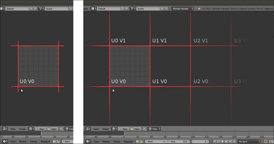
The default U0/V0 tile space and the possible consecutive other tile spaces
On the left-hand side, you can see, highlighted with red lines, the single UV tile that at present is the standard for Blender, which is identified by the UV coordinates 0 and 0: that is, U (horizontal) = 0 and V (vertical) = 0.
Although not visible in the UV/Image Editor window, all the other possible consecutive tiles can be identified by the corresponding UV coordinates, as shown on the right-hand side of the preceding screenshot (again, highlighted with red lines). So, adjacent to the tile U0/V0, we can have the row with the tiles U1/V0, U2/V0, and so on, but we can also go upwards: U0/V1, U1/V1, U2/V1, and so on.
To help you identify the tiles, Blender will show you the amount of pixels and also the number of tiles you are moving the islands in the toolbar of the UV/Image Editor window. In the following screenshot, the arm islands have been moved horizontally (on the negative x axis) by -3072.000 pixels; this is correct because that's exactly the X size of the grid image we loaded in the previous recipes. In fact, in the toolbar of the UV/Image Editor window, while moving the islands we can read D: -3072.000 (pixels) and (inside brackets) 1.0000 (tile) along X; effectively, 3072 pixels = 1 tile.
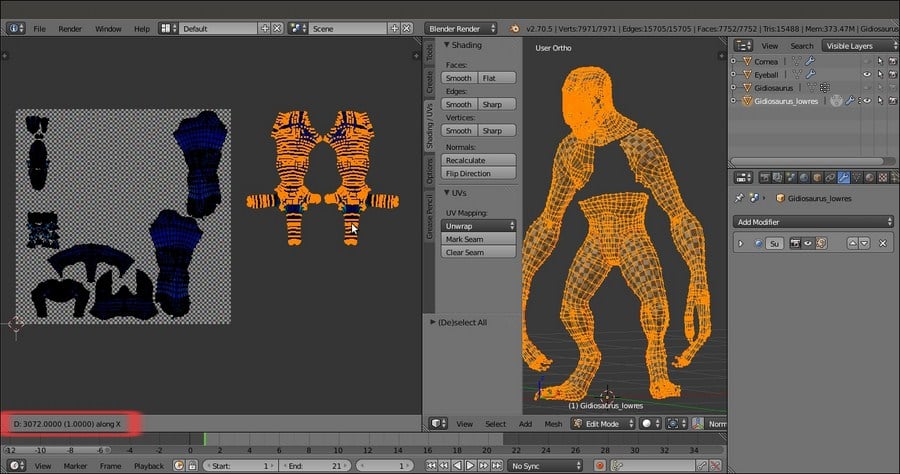
Moving the arm islands to the U1/V0 tile space
When moving UV islands from tile to tile, remember to check that the Constrain to Image Bounds item in the UVs menu on the toolbar of the UV/Image Editor window is disabled; also, enabling the Normalized item inside the Display subpanel under the N key Properties sidepanel of the same editor window will display the UV coordinates from 0.0 to 1.0, rather than in pixels. More, pressing the Ctrl key while moving the islands will constrain the movement to intervals, making it easy to translate them to exactly 1 tile space.
Because at the moment Blender doesn't support the UDIM UV Mapping standard, simply moving an island outside the default U0/V0 tile, for example to U1/V0, will repeat the image you loaded in the U0/V0 tile and on the faces associated with the moved islands. To solve this, it's necessary, after moving the islands, to assign a different material, if necessary with its own different image textures, to each group of vertices/faces associated with each tile space. So, if you shared your islands over 4 tiles, you need to assign 4 different materials to your object, and each material must load the proper image texture.
The goal of this process is obviously to obtain bigger islands mapped with bigger texture images, by selecting all the islands, scaling them bigger together using the largest ones as a guide, and then tweaking their position and distribution.
One last thing: it is also better to unwrap the corneas and eyes (which are separate objects from the Gidiosaurus body mesh) and add their islands to the tiles where you put the face, mouth, teeth, and so on (use the Draw Other Objects tool in the View menu of the UV/Image Editor window to also show the UV islands of the other nonjoined unwrapped objects):
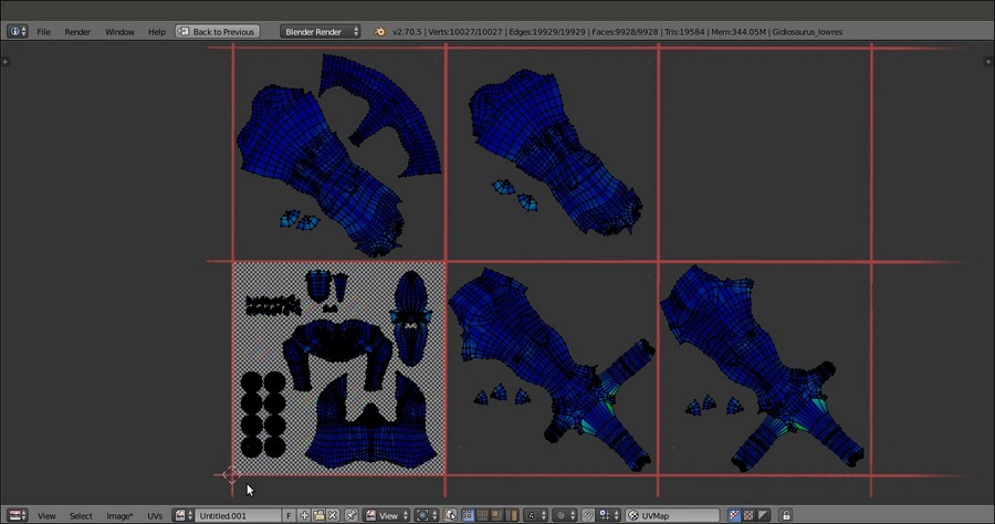
UV islands unwrapped, following the UDIM UV Mapping standard
In our case, we assigned the Gidiosaurus body islands to 5 different tiles, U0/V0, U1/V0, U2/V0, U0/V1, and U1/V1, so we'll have to assign 5 different materials. However, we will cover this in a later recipe.
Note that for exposition purposes only, in the preceding screenshot, you can see the cornea and eye islands together with the Gidiosaurus body islands because I temporarily joined the objects; however, it's usually better to maintain the eyes and corneas as separate objects from the main body.
Getting ready
First, we'll try to recalculate the unwrap of some of the islands by modifying the seams of the mesh.
Before we start though, let's see if we can improve some of the visibility of the UV islands in the UV/Image Editor:
- Put the mouse cursor in the UV/Image Editor window and press the N key.
- In the Properties sidepanel that appears by pressing the N key on the right-hand side of the window, go to the Display subpanel and click on the Black or White button (depending on your preference) under the UV item. Check also the Smooth item box.
- Also, check the Stretch item, which even though it was made for a different purpose, can increase the visibility of the islands a lot.
- Press N again to get rid of the Properties sidepanel.
All these options enabled should make the islands more easily readable in the UV/Image Editor window:
The UV islands made more easily readable by the enabled items
Now we can start with the editing; initially, we are going to freeze the islands that we don't want to modify because their unwrap is either satisfactory, or we will deal with it later. So, perform the following steps:
- Press A to select all the islands, then by putting the mouse pointer on the two pelvis island halves and pressing Shift + L, multi-deselect them; press the P key to pin the remaining selected UV islands and then A to deselect everything:
To the right-hand side, the pinned UV islands
- Zoom in on the islands of the pelvis, select both the left and right outer edge-loops, as shown in the following left image, and press P to pin them.
- Go to the 3D view and clear only the front part of the median seam on the pelvis. To do this, start to clear the seam from the front edges, go down and stop where it crosses the horizontal seam that passes the bottom part of the groin and legs, and leave the back part of the vertical median seam still marked:
Pinning the extreme vertices in the UV/Image Editor, and editing the seam on the mesh
- Go into Face selection mode and select all the faces of the pelvis; put the mouse pointer in the 3D view and press U | Unwrap (alternatively, go into the UV/Image Editor and press E):
Unwrapping again with the pinning and a different seam
The island will keep the previous position because of the pinned edges, and is now unwrapped as one single piece (with the obvious exception of the seam on the back).
- We won't modify the pelvis island any further, so select all its vertices and press P to pin all of them and then deselect them.
- Press A in the 3D view to select all the faces of the mesh and make all the islands visible in the UV/Image Editor. Note that they are all pinned at the moment, so just select the vertices you want to unpin (Alt + P) in the islands of the tongue and inner mouth. Then, clear the median seam in the corresponding pieces on the mesh, and press E again:
Re-unwrapping the tongue and inner mouth areas
- Select the UV vertices of the resulting islands and unpin them all; next, pin just one vertex at the top of the islands and one at the bottom, and unwrap again. This will result in a more organically distributed unwrap of the parts:
Re-unwrapping again with a different pinning
- Select all the faces of the mesh, and then all the islands in the UV/Image Editor window. Press Ctrl + A to average their relative size and adjust their position in the default tile space:
The rearranged UV islands
Now, let's work on the head piece that, as in every character, should be the most important and well-finished piece.
At the moment, the face is made using two separate islands; although this won't be visible in the final textured rendering of our character, it's always better, if possible, to join them in order to have a single piece, especially in the front mesh faces. Due to the elongated snout of the character, if we were to unwrap the head as a single piece simply without the median seam, we wouldn't get a nice evenly mapped result, so we must divide the whole head into more pieces.
Actually, we can take advantage of the fact that the Gidiosaurus is wearing a helmet and that most of the head will be covered by it; this allows us to easily split the face from the rest of the mesh, hiding the seams under the helmet.
- Go into Edge selection mode and mark the seams, dividing the face from the cranium and neck as shown in the following screenshots. Select the crossing edge-loops, and then clear the unnecessary parts:
New seams for the character's head part 1
- Also clear the median seam in the upper face part, and under the seam on the bottom jaw, leaving it only on the front mandible and on the back of the cranium and neck:
New seams for the character's head part 2
- Go in the Face selection mode and select only the face section of the mesh, and then press E to unwrap. The new unwrap comes upside down, so select all the UV vertices and rotate the island by 180 degrees:
The character's face unwrapped
- Select the cranium/neck section on the mesh and repeat the process:
The rest of the head mesh unwrapped as a whole piece
- Now, select all the faces of the mesh and all the islands in the UV/Image Editor, and press Ctrl + A to average their reciprocal size.
- Once again, adjust the position of the islands inside the UV tile (Ctrl + P to automatically pack them inside the available space, and then tweak their position, rotation, and scale):
The character's UV islands packed inside the default U0/V0 tile space
Starting from the UV unwrap in the previous recipe, we improved some of the islands by joining together the halves representing common mesh parts. When doing this, we tried to retain the already good parts of the unwrap by pinning the UV vertices that we didn't want to modify; this way, the new unwrap process was forced to calculate the position of the unpinned vertices using the constraints of the pinned ones (pelvis, tongue, and inner mouth). In other cases, we totally cleared the old seams on the model and marked new ones, in order to have a completely new unwrap of the mesh part (the head), we also used the character furniture (such as the armor) to hide the seams (which in any case, won't be visible at all).
At this point, looking at the UV/Image Editor window containing the islands, it's evident that if we want to keep several parts in proportion to each other, some of the islands are a little too small to give a good amount of detail when texturing; for example, the Gidiosaurus's face.
A technique for a good unwrap that is the current standard in the industry is UDIM UV Mapping, which means U-Dimension; basically, after the usual unwrap, the islands are scaled bigger and placed outside the default U0/V0 tile space.
Look at the following screenshots, showing the Blender UV/Image Editor window:
The default U0/V0 tile space and the possible consecutive other tile spaces
On the left-hand side, you can see, highlighted with red lines, the single UV tile that at present is the standard for Blender, which is identified by the UV coordinates 0 and 0: that is, U (horizontal) = 0 and V (vertical) = 0.
Although not visible in the UV/Image Editor window, all the other possible consecutive tiles can be identified by the corresponding UV coordinates, as shown on the right-hand side of the preceding screenshot (again, highlighted with red lines). So, adjacent to the tile U0/V0, we can have the row with the tiles U1/V0, U2/V0, and so on, but we can also go upwards: U0/V1, U1/V1, U2/V1, and so on.
To help you identify the tiles, Blender will show you the amount of pixels and also the number of tiles you are moving the islands in the toolbar of the UV/Image Editor window. In the following screenshot, the arm islands have been moved horizontally (on the negative x axis) by -3072.000 pixels; this is correct because that's exactly the X size of the grid image we loaded in the previous recipes. In fact, in the toolbar of the UV/Image Editor window, while moving the islands we can read D: -3072.000 (pixels) and (inside brackets) 1.0000 (tile) along X; effectively, 3072 pixels = 1 tile.
Moving the arm islands to the U1/V0 tile space
When moving UV islands from tile to tile, remember to check that the Constrain to Image Bounds item in the UVs menu on the toolbar of the UV/Image Editor window is disabled; also, enabling the Normalized item inside the Display subpanel under the N key Properties sidepanel of the same editor window will display the UV coordinates from 0.0 to 1.0, rather than in pixels. More, pressing the Ctrl key while moving the islands will constrain the movement to intervals, making it easy to translate them to exactly 1 tile space.
Because at the moment Blender doesn't support the UDIM UV Mapping standard, simply moving an island outside the default U0/V0 tile, for example to U1/V0, will repeat the image you loaded in the U0/V0 tile and on the faces associated with the moved islands. To solve this, it's necessary, after moving the islands, to assign a different material, if necessary with its own different image textures, to each group of vertices/faces associated with each tile space. So, if you shared your islands over 4 tiles, you need to assign 4 different materials to your object, and each material must load the proper image texture.
The goal of this process is obviously to obtain bigger islands mapped with bigger texture images, by selecting all the islands, scaling them bigger together using the largest ones as a guide, and then tweaking their position and distribution.
One last thing: it is also better to unwrap the corneas and eyes (which are separate objects from the Gidiosaurus body mesh) and add their islands to the tiles where you put the face, mouth, teeth, and so on (use the Draw Other Objects tool in the View menu of the UV/Image Editor window to also show the UV islands of the other nonjoined unwrapped objects):
UV islands unwrapped, following the UDIM UV Mapping standard
In our case, we assigned the Gidiosaurus body islands to 5 different tiles, U0/V0, U1/V0, U2/V0, U0/V1, and U1/V1, so we'll have to assign 5 different materials. However, we will cover this in a later recipe.
Note that for exposition purposes only, in the preceding screenshot, you can see the cornea and eye islands together with the Gidiosaurus body islands because I temporarily joined the objects; however, it's usually better to maintain the eyes and corneas as separate objects from the main body.
How to do it…
Now we can start with the editing; initially, we are going to freeze the islands that we don't want to modify because their unwrap is either satisfactory, or we will deal with it later. So, perform the following steps:
- Press A to select all the islands, then by putting the mouse pointer on the two pelvis island halves and pressing Shift + L, multi-deselect them; press the P key to pin the remaining selected UV islands and then A to deselect everything:
To the right-hand side, the pinned UV islands
- Zoom in on the islands of the pelvis, select both the left and right outer edge-loops, as shown in the following left image, and press P to pin them.
- Go to the 3D view and clear only the front part of the median seam on the pelvis. To do this, start to clear the seam from the front edges, go down and stop where it crosses the horizontal seam that passes the bottom part of the groin and legs, and leave the back part of the vertical median seam still marked:
Pinning the extreme vertices in the UV/Image Editor, and editing the seam on the mesh
- Go into Face selection mode and select all the faces of the pelvis; put the mouse pointer in the 3D view and press U | Unwrap (alternatively, go into the UV/Image Editor and press E):
Unwrapping again with the pinning and a different seam
The island will keep the previous position because of the pinned edges, and is now unwrapped as one single piece (with the obvious exception of the seam on the back).
- We won't modify the pelvis island any further, so select all its vertices and press P to pin all of them and then deselect them.
- Press A in the 3D view to select all the faces of the mesh and make all the islands visible in the UV/Image Editor. Note that they are all pinned at the moment, so just select the vertices you want to unpin (Alt + P) in the islands of the tongue and inner mouth. Then, clear the median seam in the corresponding pieces on the mesh, and press E again:
Re-unwrapping the tongue and inner mouth areas
- Select the UV vertices of the resulting islands and unpin them all; next, pin just one vertex at the top of the islands and one at the bottom, and unwrap again. This will result in a more organically distributed unwrap of the parts:
Re-unwrapping again with a different pinning
- Select all the faces of the mesh, and then all the islands in the UV/Image Editor window. Press Ctrl + A to average their relative size and adjust their position in the default tile space:
The rearranged UV islands
Now, let's work on the head piece that, as in every character, should be the most important and well-finished piece.
At the moment, the face is made using two separate islands; although this won't be visible in the final textured rendering of our character, it's always better, if possible, to join them in order to have a single piece, especially in the front mesh faces. Due to the elongated snout of the character, if we were to unwrap the head as a single piece simply without the median seam, we wouldn't get a nice evenly mapped result, so we must divide the whole head into more pieces.
Actually, we can take advantage of the fact that the Gidiosaurus is wearing a helmet and that most of the head will be covered by it; this allows us to easily split the face from the rest of the mesh, hiding the seams under the helmet.
- Go into Edge selection mode and mark the seams, dividing the face from the cranium and neck as shown in the following screenshots. Select the crossing edge-loops, and then clear the unnecessary parts:
New seams for the character's head part 1
- Also clear the median seam in the upper face part, and under the seam on the bottom jaw, leaving it only on the front mandible and on the back of the cranium and neck:
New seams for the character's head part 2
- Go in the Face selection mode and select only the face section of the mesh, and then press E to unwrap. The new unwrap comes upside down, so select all the UV vertices and rotate the island by 180 degrees:
The character's face unwrapped
- Select the cranium/neck section on the mesh and repeat the process:
The rest of the head mesh unwrapped as a whole piece
- Now, select all the faces of the mesh and all the islands in the UV/Image Editor, and press Ctrl + A to average their reciprocal size.
- Once again, adjust the position of the islands inside the UV tile (Ctrl + P to automatically pack them inside the available space, and then tweak their position, rotation, and scale):
The character's UV islands packed inside the default U0/V0 tile space
Starting from the UV unwrap in the previous recipe, we improved some of the islands by joining together the halves representing common mesh parts. When doing this, we tried to retain the already good parts of the unwrap by pinning the UV vertices that we didn't want to modify; this way, the new unwrap process was forced to calculate the position of the unpinned vertices using the constraints of the pinned ones (pelvis, tongue, and inner mouth). In other cases, we totally cleared the old seams on the model and marked new ones, in order to have a completely new unwrap of the mesh part (the head), we also used the character furniture (such as the armor) to hide the seams (which in any case, won't be visible at all).
At this point, looking at the UV/Image Editor window containing the islands, it's evident that if we want to keep several parts in proportion to each other, some of the islands are a little too small to give a good amount of detail when texturing; for example, the Gidiosaurus's face.
A technique for a good unwrap that is the current standard in the industry is UDIM UV Mapping, which means U-Dimension; basically, after the usual unwrap, the islands are scaled bigger and placed outside the default U0/V0 tile space.
Look at the following screenshots, showing the Blender UV/Image Editor window:
The default U0/V0 tile space and the possible consecutive other tile spaces
On the left-hand side, you can see, highlighted with red lines, the single UV tile that at present is the standard for Blender, which is identified by the UV coordinates 0 and 0: that is, U (horizontal) = 0 and V (vertical) = 0.
Although not visible in the UV/Image Editor window, all the other possible consecutive tiles can be identified by the corresponding UV coordinates, as shown on the right-hand side of the preceding screenshot (again, highlighted with red lines). So, adjacent to the tile U0/V0, we can have the row with the tiles U1/V0, U2/V0, and so on, but we can also go upwards: U0/V1, U1/V1, U2/V1, and so on.
To help you identify the tiles, Blender will show you the amount of pixels and also the number of tiles you are moving the islands in the toolbar of the UV/Image Editor window. In the following screenshot, the arm islands have been moved horizontally (on the negative x axis) by -3072.000 pixels; this is correct because that's exactly the X size of the grid image we loaded in the previous recipes. In fact, in the toolbar of the UV/Image Editor window, while moving the islands we can read D: -3072.000 (pixels) and (inside brackets) 1.0000 (tile) along X; effectively, 3072 pixels = 1 tile.
Moving the arm islands to the U1/V0 tile space
When moving UV islands from tile to tile, remember to check that the Constrain to Image Bounds item in the UVs menu on the toolbar of the UV/Image Editor window is disabled; also, enabling the Normalized item inside the Display subpanel under the N key Properties sidepanel of the same editor window will display the UV coordinates from 0.0 to 1.0, rather than in pixels. More, pressing the Ctrl key while moving the islands will constrain the movement to intervals, making it easy to translate them to exactly 1 tile space.
Because at the moment Blender doesn't support the UDIM UV Mapping standard, simply moving an island outside the default U0/V0 tile, for example to U1/V0, will repeat the image you loaded in the U0/V0 tile and on the faces associated with the moved islands. To solve this, it's necessary, after moving the islands, to assign a different material, if necessary with its own different image textures, to each group of vertices/faces associated with each tile space. So, if you shared your islands over 4 tiles, you need to assign 4 different materials to your object, and each material must load the proper image texture.
The goal of this process is obviously to obtain bigger islands mapped with bigger texture images, by selecting all the islands, scaling them bigger together using the largest ones as a guide, and then tweaking their position and distribution.
One last thing: it is also better to unwrap the corneas and eyes (which are separate objects from the Gidiosaurus body mesh) and add their islands to the tiles where you put the face, mouth, teeth, and so on (use the Draw Other Objects tool in the View menu of the UV/Image Editor window to also show the UV islands of the other nonjoined unwrapped objects):
UV islands unwrapped, following the UDIM UV Mapping standard
In our case, we assigned the Gidiosaurus body islands to 5 different tiles, U0/V0, U1/V0, U2/V0, U0/V1, and U1/V1, so we'll have to assign 5 different materials. However, we will cover this in a later recipe.
Note that for exposition purposes only, in the preceding screenshot, you can see the cornea and eye islands together with the Gidiosaurus body islands because I temporarily joined the objects; however, it's usually better to maintain the eyes and corneas as separate objects from the main body.
How it works…
Starting from the UV unwrap in the previous recipe, we improved some of the islands by joining together the halves representing common mesh parts. When doing this, we tried to retain the already good parts of the unwrap by pinning the UV vertices that we didn't want to modify; this way, the new unwrap process was forced to calculate the position of the unpinned vertices using the constraints of the pinned ones (pelvis, tongue, and inner mouth). In other cases, we totally cleared the old seams on the model and marked new ones, in order to have a completely new unwrap of the mesh part (the head), we also used the character furniture (such as the armor) to hide the seams (which in any case, won't be visible at all).
At this point, looking at the UV/Image Editor window containing the islands, it's evident that if we want to keep several parts in proportion to each other, some of the islands are a little too small to give a good amount of detail when texturing; for example, the Gidiosaurus's face.
A technique for a good unwrap that is the current standard in the industry is UDIM UV Mapping, which means U-Dimension; basically, after the usual unwrap, the islands are scaled bigger and placed outside the default U0/V0 tile space.
Look at the following screenshots, showing the Blender UV/Image Editor window:
The default U0/V0 tile space and the possible consecutive other tile spaces
On the left-hand side, you can see, highlighted with red lines, the single UV tile that at present is the standard for Blender, which is identified by the UV coordinates 0 and 0: that is, U (horizontal) = 0 and V (vertical) = 0.
Although not visible in the UV/Image Editor window, all the other possible consecutive tiles can be identified by the corresponding UV coordinates, as shown on the right-hand side of the preceding screenshot (again, highlighted with red lines). So, adjacent to the tile U0/V0, we can have the row with the tiles U1/V0, U2/V0, and so on, but we can also go upwards: U0/V1, U1/V1, U2/V1, and so on.
To help you identify the tiles, Blender will show you the amount of pixels and also the number of tiles you are moving the islands in the toolbar of the UV/Image Editor window. In the following screenshot, the arm islands have been moved horizontally (on the negative x axis) by -3072.000 pixels; this is correct because that's exactly the X size of the grid image we loaded in the previous recipes. In fact, in the toolbar of the UV/Image Editor window, while moving the islands we can read D: -3072.000 (pixels) and (inside brackets) 1.0000 (tile) along X; effectively, 3072 pixels = 1 tile.
Moving the arm islands to the U1/V0 tile space
When moving UV islands from tile to tile, remember to check that the Constrain to Image Bounds item in the UVs menu on the toolbar of the UV/Image Editor window is disabled; also, enabling the Normalized item inside the Display subpanel under the N key Properties sidepanel of the same editor window will display the UV coordinates from 0.0 to 1.0, rather than in pixels. More, pressing the Ctrl key while moving the islands will constrain the movement to intervals, making it easy to translate them to exactly 1 tile space.
Because at the moment Blender doesn't support the UDIM UV Mapping standard, simply moving an island outside the default U0/V0 tile, for example to U1/V0, will repeat the image you loaded in the U0/V0 tile and on the faces associated with the moved islands. To solve this, it's necessary, after moving the islands, to assign a different material, if necessary with its own different image textures, to each group of vertices/faces associated with each tile space. So, if you shared your islands over 4 tiles, you need to assign 4 different materials to your object, and each material must load the proper image texture.
The goal of this process is obviously to obtain bigger islands mapped with bigger texture images, by selecting all the islands, scaling them bigger together using the largest ones as a guide, and then tweaking their position and distribution.
One last thing: it is also better to unwrap the corneas and eyes (which are separate objects from the Gidiosaurus body mesh) and add their islands to the tiles where you put the face, mouth, teeth, and so on (use the Draw Other Objects tool in the View menu of the UV/Image Editor window to also show the UV islands of the other nonjoined unwrapped objects):
UV islands unwrapped, following the UDIM UV Mapping standard
In our case, we assigned the Gidiosaurus body islands to 5 different tiles, U0/V0, U1/V0, U2/V0, U0/V1, and U1/V1, so we'll have to assign 5 different materials. However, we will cover this in a later recipe.
Note that for exposition purposes only, in the preceding screenshot, you can see the cornea and eye islands together with the Gidiosaurus body islands because I temporarily joined the objects; however, it's usually better to maintain the eyes and corneas as separate objects from the main body.
There's more…
At this point, looking at the UV/Image Editor window containing the islands, it's evident that if we want to keep several parts in proportion to each other, some of the islands are a little too small to give a good amount of detail when texturing; for example, the Gidiosaurus's face.
A technique for a good unwrap that is the current standard in the industry is UDIM UV Mapping, which means U-Dimension; basically, after the usual unwrap, the islands are scaled bigger and placed outside the default U0/V0 tile space.
Look at the following screenshots, showing the Blender UV/Image Editor window:
The default U0/V0 tile space and the possible consecutive other tile spaces
On the left-hand side, you can see, highlighted with red lines, the single UV tile that at present is the standard for Blender, which is identified by the UV coordinates 0 and 0: that is, U (horizontal) = 0 and V (vertical) = 0.
Although not visible in the UV/Image Editor window, all the other possible consecutive tiles can be identified by the corresponding UV coordinates, as shown on the right-hand side of the preceding screenshot (again, highlighted with red lines). So, adjacent to the tile U0/V0, we can have the row with the tiles U1/V0, U2/V0, and so on, but we can also go upwards: U0/V1, U1/V1, U2/V1, and so on.
To help you identify the tiles, Blender will show you the amount of pixels and also the number of tiles you are moving the islands in the toolbar of the UV/Image Editor window. In the following screenshot, the arm islands have been moved horizontally (on the negative x axis) by -3072.000 pixels; this is correct because that's exactly the X size of the grid image we loaded in the previous recipes. In fact, in the toolbar of the UV/Image Editor window, while moving the islands we can read D: -3072.000 (pixels) and (inside brackets) 1.0000 (tile) along X; effectively, 3072 pixels = 1 tile.
Moving the arm islands to the U1/V0 tile space
When moving UV islands from tile to tile, remember to check that the Constrain to Image Bounds item in the UVs menu on the toolbar of the UV/Image Editor window is disabled; also, enabling the Normalized item inside the Display subpanel under the N key Properties sidepanel of the same editor window will display the UV coordinates from 0.0 to 1.0, rather than in pixels. More, pressing the Ctrl key while moving the islands will constrain the movement to intervals, making it easy to translate them to exactly 1 tile space.
Because at the moment Blender doesn't support the UDIM UV Mapping standard, simply moving an island outside the default U0/V0 tile, for example to U1/V0, will repeat the image you loaded in the U0/V0 tile and on the faces associated with the moved islands. To solve this, it's necessary, after moving the islands, to assign a different material, if necessary with its own different image textures, to each group of vertices/faces associated with each tile space. So, if you shared your islands over 4 tiles, you need to assign 4 different materials to your object, and each material must load the proper image texture.
The goal of this process is obviously to obtain bigger islands mapped with bigger texture images, by selecting all the islands, scaling them bigger together using the largest ones as a guide, and then tweaking their position and distribution.
One last thing: it is also better to unwrap the corneas and eyes (which are separate objects from the Gidiosaurus body mesh) and add their islands to the tiles where you put the face, mouth, teeth, and so on (use the Draw Other Objects tool in the View menu of the UV/Image Editor window to also show the UV islands of the other nonjoined unwrapped objects):
UV islands unwrapped, following the UDIM UV Mapping standard
In our case, we assigned the Gidiosaurus body islands to 5 different tiles, U0/V0, U1/V0, U2/V0, U0/V1, and U1/V1, so we'll have to assign 5 different materials. However, we will cover this in a later recipe.
Note that for exposition purposes only, in the preceding screenshot, you can see the cornea and eye islands together with the Gidiosaurus body islands because I temporarily joined the objects; however, it's usually better to maintain the eyes and corneas as separate objects from the main body.
Now, we are going to use a much easier and faster method to do the unwrapping of the Armor: the Smart UV Project tool.
The first thing to do is to prepare the armor pieces for the unwrap process, so perform the following steps:
- Starting from the last
Gidiosaurus_unwrap.blendfile you saved, click on the 13th scene layer to reveal the armor and at the same time, hide the Gidiosaurus_lowres object. - Go to the Outliner and select the first item, the Breastplate; then, use Shift to multiselect all the other visible objects.
- Press Ctrl + J to join them into a single object, and then in the Outliner, rename the result as
Armor. - Go to the Object Modifiers window and expand the Mirror modifier subpanel; be sure that the Clipping item is activated and click on the Apply button:

The Armor as a single object and the Mirror modifier
Here is the unwrap process:
- Press Tab to go into Edit Mode and press the A key to select all the vertices of the Armor.
- With the mouse cursor in the 3D view, press the U key, and in the UV Mapping pop-up menu that just appeared, select the second item from the top, Smart UV Project.
- A second pop-up appears with some options that you can leave as they are, besides Angle Limit (the maximum angle in the mesh used by the tool to separate the islands), which by default is set to 66.00; raise it to the maximum, which is 89.00, and then click on the big OK button:

The Smart UV Project tool
The mesh has been divided into several smaller unwrapped parts and is automatically packed inside the U0/V0 UV tile.
- Select all the islands in the UV/Image Editor window, click on the small double-arrow icon on the toolbar, close to the New and Open buttons, and select the Untitled.001 image (the same grid image we used for the Gidiosaurus unwrap).
- Press Tab to go out of Edit Mode:

The unwrapped Armor
Considering the amount of tiny islands that the tool created, it's better to separate the big armor parts (basically, the plates) from the smaller ones (belts, borders, and so on) and re-unwrap them with the Smart UV Project tool, as we did for the Gidiosaurus body in the previous recipe; then, place them into two adjacent tiles:

The Armor islands inside the U0/V0 and U1/V0 tiles
Getting ready
The first thing to do is to prepare the armor pieces for the unwrap process, so perform the following steps:
- Starting from the last
Gidiosaurus_unwrap.blendfile you saved, click on the 13th scene layer to reveal the armor and at the same time, hide the Gidiosaurus_lowres object. - Go to the Outliner and select the first item, the Breastplate; then, use Shift to multiselect all the other visible objects.
- Press Ctrl + J to join them into a single object, and then in the Outliner, rename the result as
Armor. - Go to the Object Modifiers window and expand the Mirror modifier subpanel; be sure that the Clipping item is activated and click on the Apply button:
The Armor as a single object and the Mirror modifier
Here is the unwrap process:
- Press Tab to go into Edit Mode and press the A key to select all the vertices of the Armor.
- With the mouse cursor in the 3D view, press the U key, and in the UV Mapping pop-up menu that just appeared, select the second item from the top, Smart UV Project.
- A second pop-up appears with some options that you can leave as they are, besides Angle Limit (the maximum angle in the mesh used by the tool to separate the islands), which by default is set to 66.00; raise it to the maximum, which is 89.00, and then click on the big OK button:
The Smart UV Project tool
The mesh has been divided into several smaller unwrapped parts and is automatically packed inside the U0/V0 UV tile.
- Select all the islands in the UV/Image Editor window, click on the small double-arrow icon on the toolbar, close to the New and Open buttons, and select the Untitled.001 image (the same grid image we used for the Gidiosaurus unwrap).
- Press Tab to go out of Edit Mode:
The unwrapped Armor
Considering the amount of tiny islands that the tool created, it's better to separate the big armor parts (basically, the plates) from the smaller ones (belts, borders, and so on) and re-unwrap them with the Smart UV Project tool, as we did for the Gidiosaurus body in the previous recipe; then, place them into two adjacent tiles:
The Armor islands inside the U0/V0 and U1/V0 tiles
How to do it…
Here is the unwrap process:
- Press Tab to go into Edit Mode and press the A key to select all the vertices of the Armor.
- With the mouse cursor in the 3D view, press the U key, and in the UV Mapping pop-up menu that just appeared, select the second item from the top, Smart UV Project.
- A second pop-up appears with some options that you can leave as they are, besides Angle Limit (the maximum angle in the mesh used by the tool to separate the islands), which by default is set to 66.00; raise it to the maximum, which is 89.00, and then click on the big OK button:
The Smart UV Project tool
The mesh has been divided into several smaller unwrapped parts and is automatically packed inside the U0/V0 UV tile.
- Select all the islands in the UV/Image Editor window, click on the small double-arrow icon on the toolbar, close to the New and Open buttons, and select the Untitled.001 image (the same grid image we used for the Gidiosaurus unwrap).
- Press Tab to go out of Edit Mode:
The unwrapped Armor
Considering the amount of tiny islands that the tool created, it's better to separate the big armor parts (basically, the plates) from the smaller ones (belts, borders, and so on) and re-unwrap them with the Smart UV Project tool, as we did for the Gidiosaurus body in the previous recipe; then, place them into two adjacent tiles:
The Armor islands inside the U0/V0 and U1/V0 tiles
At this point, when we look at the Gidiosaurus mesh, we realize that some detail in the model is still missing; for example, the lower teeth. In fact, we modeled the mouth closed and the lower teeth, enclosed in the upper mouth rim, weren't visible.
It's now time to add them; in fact, even though we have already done the unwrapping stage, it's still possible to modify the mesh further and also update the UV islands accordingly.
Start from the last Gidiosaurus_unwrap.blend file you saved:
- Press N to open the Properties 3D view sidepanel, and disable the Textured Solid item under the Shading subpanel.
- Click on the 11th scene layer button to reveal the Gidiosaurus_lowres object and select it; go into the Side view, zoom in to the head, and enter Edit Mode. Press the A key to select all the vertices of the mesh.
- Put the mouse pointer inside the UV/Image Editor, select all the UV vertices (again the A key), and pin them by pressing the P key; then deselect everything (the A key once more).
We can now start to add new teeth:
- Select the vertices of one lower tooth and press Shift + D to duplicate it; using the Transform Orientation widget set to Normal, scale it smaller, rotate and modify it a bit, and then move it in a new position along the mandible rim:

The new added tooth
- Repeat the process to create the bottom teeth row on the left-hand side of the mandible:

Adding the missing teeth
- Go out of the Edit Mode and put the 3D Cursor at the pivot point of the mesh (coincidentally, at the center of the scene), and then press the period key (.) to set the Pivot Point around the 3D Cursor.
- Press 1 on the numpad to go in the Front view, enter Edit Mode again, and select all the new teeth; press Shift + D to duplicate them, and then right-click; then, press Ctrl + M | X | Enter to mirror them on the x axis to the right-hand side of the mandible.
- Press Ctrl + N to recalculate the normals and go out of the Edit Mode:

The new teeth mirrored on the x axis
Now, we must adjust the rim of the mandible where we added the new teeth, in order to create the alveoli.
- Go back into the Edit Mode and start to add vertical edge-loops on the lower mouth rim, in order to create more geometry for the alveoli:

Adding new edge-loops
- Click on the Options tab under the Tool Shelf to the left-hand side of the 3D window and enable the X Mirror item under the Mesh Options subpanel.
- Tweak the vertices to create the alveoli around the new teeth; enable the Subdivision Surface modifier visibility during Edit Mode in order to have better feedback:

Modeling the alveoli
- Press Alt + S to scale the teeth vertices on their normals, in order to thicken them, and add edge-loops where needed to make the transition from the alveoli to inner mouth as natural as possible.
When you are done, it's time to update the unwrapped UV layer with the new modifications.
- In Edit Mode, first select the vertices of the new teeth. Because we made them by duplicating one of the already unwrapped fangs, the new teeth will share the same UV island. In the UV/Image Editor, press A to select all their UV vertices and Alt + P to unpin them, and then press E for a new unwrap.
- Scale the new teeth islands to 0.200, and then select the original teeth on the mesh; adjust the size and position of the new islands based on the old ones and then pin them.
- Now, switch to the Face selection mode and select the Gidiosaurus face; in the UV/Image Editor window, unpin all the vertices of its island (Alt + P), and then pin only the vertices of certain areas such as the eyes, nose, and upper outside edge-loop (P key).
With this method, the unwrap of all the new geometry gets recalculated together with the old one. Thanks to the pinned UV vertices, it will keep the previous size and position as much as possible. In the following image, you can see the face island before (left) and after (right):

The updated unwrap
Note that you need to recalculate the unwrap for all the islands involved in the mesh's modification, and then save the file.
Getting ready
Start from the last Gidiosaurus_unwrap.blend file you saved:
- Press N to open the Properties 3D view sidepanel, and disable the Textured Solid item under the Shading subpanel.
- Click on the 11th scene layer button to reveal the Gidiosaurus_lowres object and select it; go into the Side view, zoom in to the head, and enter Edit Mode. Press the A key to select all the vertices of the mesh.
- Put the mouse pointer inside the UV/Image Editor, select all the UV vertices (again the A key), and pin them by pressing the P key; then deselect everything (the A key once more).
We can now start to add new teeth:
- Select the vertices of one lower tooth and press Shift + D to duplicate it; using the Transform Orientation widget set to Normal, scale it smaller, rotate and modify it a bit, and then move it in a new position along the mandible rim:
The new added tooth
- Repeat the process to create the bottom teeth row on the left-hand side of the mandible:
Adding the missing teeth
- Go out of the Edit Mode and put the 3D Cursor at the pivot point of the mesh (coincidentally, at the center of the scene), and then press the period key (.) to set the Pivot Point around the 3D Cursor.
- Press 1 on the numpad to go in the Front view, enter Edit Mode again, and select all the new teeth; press Shift + D to duplicate them, and then right-click; then, press Ctrl + M | X | Enter to mirror them on the x axis to the right-hand side of the mandible.
- Press Ctrl + N to recalculate the normals and go out of the Edit Mode:
The new teeth mirrored on the x axis
Now, we must adjust the rim of the mandible where we added the new teeth, in order to create the alveoli.
- Go back into the Edit Mode and start to add vertical edge-loops on the lower mouth rim, in order to create more geometry for the alveoli:
Adding new edge-loops
- Click on the Options tab under the Tool Shelf to the left-hand side of the 3D window and enable the X Mirror item under the Mesh Options subpanel.
- Tweak the vertices to create the alveoli around the new teeth; enable the Subdivision Surface modifier visibility during Edit Mode in order to have better feedback:
Modeling the alveoli
- Press Alt + S to scale the teeth vertices on their normals, in order to thicken them, and add edge-loops where needed to make the transition from the alveoli to inner mouth as natural as possible.
When you are done, it's time to update the unwrapped UV layer with the new modifications.
- In Edit Mode, first select the vertices of the new teeth. Because we made them by duplicating one of the already unwrapped fangs, the new teeth will share the same UV island. In the UV/Image Editor, press A to select all their UV vertices and Alt + P to unpin them, and then press E for a new unwrap.
- Scale the new teeth islands to 0.200, and then select the original teeth on the mesh; adjust the size and position of the new islands based on the old ones and then pin them.
- Now, switch to the Face selection mode and select the Gidiosaurus face; in the UV/Image Editor window, unpin all the vertices of its island (Alt + P), and then pin only the vertices of certain areas such as the eyes, nose, and upper outside edge-loop (P key).
With this method, the unwrap of all the new geometry gets recalculated together with the old one. Thanks to the pinned UV vertices, it will keep the previous size and position as much as possible. In the following image, you can see the face island before (left) and after (right):
The updated unwrap
Note that you need to recalculate the unwrap for all the islands involved in the mesh's modification, and then save the file.
How to do it…
We can now start to add new teeth:
- Select the vertices of one lower tooth and press Shift + D to duplicate it; using the Transform Orientation widget set to Normal, scale it smaller, rotate and modify it a bit, and then move it in a new position along the mandible rim:
The new added tooth
- Repeat the process to create the bottom teeth row on the left-hand side of the mandible:
Adding the missing teeth
- Go out of the Edit Mode and put the 3D Cursor at the pivot point of the mesh (coincidentally, at the center of the scene), and then press the period key (.) to set the Pivot Point around the 3D Cursor.
- Press 1 on the numpad to go in the Front view, enter Edit Mode again, and select all the new teeth; press Shift + D to duplicate them, and then right-click; then, press Ctrl + M | X | Enter to mirror them on the x axis to the right-hand side of the mandible.
- Press Ctrl + N to recalculate the normals and go out of the Edit Mode:
The new teeth mirrored on the x axis
Now, we must adjust the rim of the mandible where we added the new teeth, in order to create the alveoli.
- Go back into the Edit Mode and start to add vertical edge-loops on the lower mouth rim, in order to create more geometry for the alveoli:
Adding new edge-loops
- Click on the Options tab under the Tool Shelf to the left-hand side of the 3D window and enable the X Mirror item under the Mesh Options subpanel.
- Tweak the vertices to create the alveoli around the new teeth; enable the Subdivision Surface modifier visibility during Edit Mode in order to have better feedback:
Modeling the alveoli
- Press Alt + S to scale the teeth vertices on their normals, in order to thicken them, and add edge-loops where needed to make the transition from the alveoli to inner mouth as natural as possible.
When you are done, it's time to update the unwrapped UV layer with the new modifications.
- In Edit Mode, first select the vertices of the new teeth. Because we made them by duplicating one of the already unwrapped fangs, the new teeth will share the same UV island. In the UV/Image Editor, press A to select all their UV vertices and Alt + P to unpin them, and then press E for a new unwrap.
- Scale the new teeth islands to 0.200, and then select the original teeth on the mesh; adjust the size and position of the new islands based on the old ones and then pin them.
- Now, switch to the Face selection mode and select the Gidiosaurus face; in the UV/Image Editor window, unpin all the vertices of its island (Alt + P), and then pin only the vertices of certain areas such as the eyes, nose, and upper outside edge-loop (P key).
With this method, the unwrap of all the new geometry gets recalculated together with the old one. Thanks to the pinned UV vertices, it will keep the previous size and position as much as possible. In the following image, you can see the face island before (left) and after (right):
The updated unwrap
Note that you need to recalculate the unwrap for all the islands involved in the mesh's modification, and then save the file.
Up until now, we have set just one UV layer whose name is, by default, UVMap (go to the Object Data window and look under the UV Maps subpanel):

The UV Maps subpanel with the UV Map coordinates layer
Actually, in Blender, it is possible to set more than one UV coordinates layer on the same object in order to mix different UV projections that can eventually also be baked into a single image map.
The names of the UV layers under the UV Maps subpanel are important, because they specify which one of the projections a material has to use for the mapping of a texture. By clicking on the + icon to the side of the UV Maps subpanel, it is possible to add a new UV layer (whose name, in this case, will be UVMap.001 by default; of course it's possible to change these names by using Ctrl + clicking on them and typing the new ones).
We are now going to add a new UV layer to the Gidiosaurus object:
- Ensure that the Gidiosaurus object is selected and go to the Object Data window under the main Properties panel to the right-hand of the screen.
- Go to the UV Maps subpanel and click on the + icon to the right-hand side of the names window; a new UV layer is added to the list, right under the first one, and its name is UVMap.001 (in case you don't see it, it may be because the window is too small; just put the mouse cursor on the = sign at the bottom of the window and drag it down to enlarge it):

The new UV coordinates layer
- Use Ctrl + left-click on the UVMap.001 item and rename it as UVMap_scales. Then, press Enter to confirm.
Now we must set the projection of the UV layer:
- Go into Edit Mode, switch to the Face selection mode, put the mouse pointer on the mesh, and press the L key to select all the faces of the skin of the Gidiosaurus mesh.
- Go to the UV/Image Editor window, select all the visible islands and unpin them (Alt + P).
- Click on the Image item on the toolbar and select the Open Image item in the pop-up menu (or else, put the mouse cursor in the UV/Image Editor window and press Alt + O); browse to the
texturesfolder and load thescales_tiles.pngimage. - With the mouse pointer in 3D view, press U and from the UV Mapping pop-up menu, select the Cube Projection item.
- In the UV/Image Editor window, select all the islands and scale them 5 times bigger (A | S | 5 | Enter):

The Cube Projection mapping
- Go out of the Edit Mode and into the Properties 3D view sidepanel, enable the Textured Solid item under the Shading subpanel to see the result of the unwrapping in the 3D viewport:

The scales_tiles.png image mapped on the model using the second UV coordinates layer
At this point, as you can see in the UV Maps subpanel, the Gidiosaurus object has 2 different UV coordinate layers, UVMap and UVMap_scales. We will use the UVMap_scales layer to map the scales image texture on the body and thereby to bake it on the first UVMap layer; this will be the one we'll use in the end for the rendering of the model. However, we'll see this in detail in the texturing and baking recipes.
Repeat the process for the Armor.
- Add a new UV layer and rename it UVMap_rust; go into Edit Mode, select all the vertices and all the islands in the UV/Image Editor window, and load the
iron_tiles.pngimage. - Switch to the Face selection mode, and in the 3D view, press U and select Reset (the last item) from the pop-up menu. Then press U again, and this time select the Cube Projection item.
- Go out of Edit Mode.
As you can see, there are a few visible seams. This will be easily fixed during the texturing stage, but for the moment we are done:

The second UV coordinates layer for the Armor
Getting ready
We are now going to add a new UV layer to the Gidiosaurus object:
- Ensure that the Gidiosaurus object is selected and go to the Object Data window under the main Properties panel to the right-hand of the screen.
- Go to the UV Maps subpanel and click on the + icon to the right-hand side of the names window; a new UV layer is added to the list, right under the first one, and its name is UVMap.001 (in case you don't see it, it may be because the window is too small; just put the mouse cursor on the = sign at the bottom of the window and drag it down to enlarge it):
The new UV coordinates layer
- Use Ctrl + left-click on the UVMap.001 item and rename it as UVMap_scales. Then, press Enter to confirm.
Now we must set the projection of the UV layer:
- Go into Edit Mode, switch to the Face selection mode, put the mouse pointer on the mesh, and press the L key to select all the faces of the skin of the Gidiosaurus mesh.
- Go to the UV/Image Editor window, select all the visible islands and unpin them (Alt + P).
- Click on the Image item on the toolbar and select the Open Image item in the pop-up menu (or else, put the mouse cursor in the UV/Image Editor window and press Alt + O); browse to the
texturesfolder and load thescales_tiles.pngimage. - With the mouse pointer in 3D view, press U and from the UV Mapping pop-up menu, select the Cube Projection item.
- In the UV/Image Editor window, select all the islands and scale them 5 times bigger (A | S | 5 | Enter):
The Cube Projection mapping
- Go out of the Edit Mode and into the Properties 3D view sidepanel, enable the Textured Solid item under the Shading subpanel to see the result of the unwrapping in the 3D viewport:
The scales_tiles.png image mapped on the model using the second UV coordinates layer
At this point, as you can see in the UV Maps subpanel, the Gidiosaurus object has 2 different UV coordinate layers, UVMap and UVMap_scales. We will use the UVMap_scales layer to map the scales image texture on the body and thereby to bake it on the first UVMap layer; this will be the one we'll use in the end for the rendering of the model. However, we'll see this in detail in the texturing and baking recipes.
Repeat the process for the Armor.
- Add a new UV layer and rename it UVMap_rust; go into Edit Mode, select all the vertices and all the islands in the UV/Image Editor window, and load the
iron_tiles.pngimage. - Switch to the Face selection mode, and in the 3D view, press U and select Reset (the last item) from the pop-up menu. Then press U again, and this time select the Cube Projection item.
- Go out of Edit Mode.
As you can see, there are a few visible seams. This will be easily fixed during the texturing stage, but for the moment we are done:
The second UV coordinates layer for the Armor
How to do it…
Now we must set the projection of the UV layer:
- Go into Edit Mode, switch to the Face selection mode, put the mouse pointer on the mesh, and press the L key to select all the faces of the skin of the Gidiosaurus mesh.
- Go to the UV/Image Editor window, select all the visible islands and unpin them (Alt + P).
- Click on the Image item on the toolbar and select the Open Image item in the pop-up menu (or else, put the mouse cursor in the UV/Image Editor window and press Alt + O); browse to the
texturesfolder and load thescales_tiles.pngimage. - With the mouse pointer in 3D view, press U and from the UV Mapping pop-up menu, select the Cube Projection item.
- In the UV/Image Editor window, select all the islands and scale them 5 times bigger (A | S | 5 | Enter):
The Cube Projection mapping
- Go out of the Edit Mode and into the Properties 3D view sidepanel, enable the Textured Solid item under the Shading subpanel to see the result of the unwrapping in the 3D viewport:
The scales_tiles.png image mapped on the model using the second UV coordinates layer
At this point, as you can see in the UV Maps subpanel, the Gidiosaurus object has 2 different UV coordinate layers, UVMap and UVMap_scales. We will use the UVMap_scales layer to map the scales image texture on the body and thereby to bake it on the first UVMap layer; this will be the one we'll use in the end for the rendering of the model. However, we'll see this in detail in the texturing and baking recipes.
Repeat the process for the Armor.
- Add a new UV layer and rename it UVMap_rust; go into Edit Mode, select all the vertices and all the islands in the UV/Image Editor window, and load the
iron_tiles.pngimage. - Switch to the Face selection mode, and in the 3D view, press U and select Reset (the last item) from the pop-up menu. Then press U again, and this time select the Cube Projection item.
- Go out of Edit Mode.
As you can see, there are a few visible seams. This will be easily fixed during the texturing stage, but for the moment we are done:
The second UV coordinates layer for the Armor
In this last recipe, we are going to see how to export the UV coordinate layers outside Blender, in order to be used as a guide to paint textures inside any 2D image editing software.
We have seen that the Gidiosaurus object and also the Armor object have more than one UV coordinate layer, so the first thing to do is to be sure to have set the right layer as the active one.
To do this, simply click on the name of the chosen layer inside the UV Maps subpanel under the Object Data window; if you are in Edit Mode, by clicking on the different names, you can also see the different layers switch in real time in the UV/Image Editor window.
After you have selected the desired UV layer, do the following:
- Click on the UVs item in the toolbar of the UV/Image Editor window, and from the menu, select the Export UV Layout item (the top item).
- You can browse the directory where the
.blendfile is saved, as the directory opens, at the bottom-left side of the screen is the Export UV Layout option panel where you can decide on several items: the size and format of the exported image, and the opacity of the islands (by default, for mysterious reasons, it is set to 25 percent rather than 100 percent). Moreover, you can decide if you want to export all the islands of the selected object or only the visible ones, and also if you want the modifiers applied to the islands (for example, the Subdivision Surface modifier). - Browse to the folder where you decided to save the UV layout of your model, or click on the side of the path in the upper line after the slash, and write the name of a new directory. Press Enter and click on the pop-up panel with the OK? Create New Directory message to confirm (this actually creates a brand new directory).
- Write the name of the UV layout in the second line and click on the Export UV Layout button at the top-right of the screen.
Note that if you want to export all the different tiles placed outside of the default U0/V0 tile space, as illustrated in the There's more… section of the Editing the UV islands recipe, at least for the moment, you have to temporarily (using Ctrl) move each island at a time to the default U0/V0 tile space and export it.
Getting ready
We have seen that the Gidiosaurus object and also the Armor object have more than one UV coordinate layer, so the first thing to do is to be sure to have set the right layer as the active one.
To do this, simply click on the name of the chosen layer inside the UV Maps subpanel under the Object Data window; if you are in Edit Mode, by clicking on the different names, you can also see the different layers switch in real time in the UV/Image Editor window.
After you have selected the desired UV layer, do the following:
- Click on the UVs item in the toolbar of the UV/Image Editor window, and from the menu, select the Export UV Layout item (the top item).
- You can browse the directory where the
.blendfile is saved, as the directory opens, at the bottom-left side of the screen is the Export UV Layout option panel where you can decide on several items: the size and format of the exported image, and the opacity of the islands (by default, for mysterious reasons, it is set to 25 percent rather than 100 percent). Moreover, you can decide if you want to export all the islands of the selected object or only the visible ones, and also if you want the modifiers applied to the islands (for example, the Subdivision Surface modifier). - Browse to the folder where you decided to save the UV layout of your model, or click on the side of the path in the upper line after the slash, and write the name of a new directory. Press Enter and click on the pop-up panel with the OK? Create New Directory message to confirm (this actually creates a brand new directory).
- Write the name of the UV layout in the second line and click on the Export UV Layout button at the top-right of the screen.
Note that if you want to export all the different tiles placed outside of the default U0/V0 tile space, as illustrated in the There's more… section of the Editing the UV islands recipe, at least for the moment, you have to temporarily (using Ctrl) move each island at a time to the default U0/V0 tile space and export it.
How to do it…
After you have selected the desired UV layer, do the following:
- Click on the UVs item in the toolbar of the UV/Image Editor window, and from the menu, select the Export UV Layout item (the top item).
- You can browse the directory where the
.blendfile is saved, as the directory opens, at the bottom-left side of the screen is the Export UV Layout option panel where you can decide on several items: the size and format of the exported image, and the opacity of the islands (by default, for mysterious reasons, it is set to 25 percent rather than 100 percent). Moreover, you can decide if you want to export all the islands of the selected object or only the visible ones, and also if you want the modifiers applied to the islands (for example, the Subdivision Surface modifier). - Browse to the folder where you decided to save the UV layout of your model, or click on the side of the path in the upper line after the slash, and write the name of a new directory. Press Enter and click on the pop-up panel with the OK? Create New Directory message to confirm (this actually creates a brand new directory).
- Write the name of the UV layout in the second line and click on the Export UV Layout button at the top-right of the screen.
Note that if you want to export all the different tiles placed outside of the default U0/V0 tile space, as illustrated in the There's more… section of the Editing the UV islands recipe, at least for the moment, you have to temporarily (using Ctrl) move each island at a time to the default U0/V0 tile space and export it.
In this chapter, we will cover the following recipes:
- Building the character's Armature from scratch
- Perfecting the Armature to also function as a rig for the Armor
- Building the character's Armature through the Human Meta-Rig
- Building the animation controls and the Inverse Kinematic
- Generating the character's Armature by using the Rigify add-on
To be able to animate our character, we have to build the rig, which in Blender is commonly referred to as an Armature, and this is the skeleton that will deform the Gidiosaurus low resolution mesh.
The rigging process in Blender can be accomplished basically in two different ways:
Building the Armature manually by hand can be a lot of work, but in my opinion, is the only way to really learn and understand how a rig works; on the other hand, the Rigify add-on gives several tools to speed up and automate the rig creation process, and this in many occasions, can be very handy.
So, the first recipe of this chapter is about the making of the Armature by hands for our Gidiosaurus.
In this first recipe, we are going to build by hands the basic rig, which is the skeleton made only by the deforming bones.
However, first, let's prepare a bit the file to be worked:
- Start Blender and open the
Gidiosaurus_unwrap_final.blendfile. - Disable the Textured Solid and Backface Culling items in the 3D view Properties sidepanel, join the 3D window with the UV/Image Editor window, and click on the 11th scene layer to have only the Gidiosaurus mesh visible in the viewport.
- Go to the Object window under the Display subpanel and enable the Wire item. This will be useful in the process in order to have an idea of the mesh topology when in Object Mode and Solid viewport shading mode. However, for the moment, press the Z key to go in the Wireframe viewport shading mode.
- Press 1 on the numpad to go in the Front view, and press 5 on the numpad again to switch to the Ortho view.
- Save the file as
Gidiosaurus_rig_from_scratch_start.blend.
Let's start:
- Be sure that the 3D Cursor is at the origin pivot point of the Gidiosaurus mesh. Put the mouse pointer in the 3D view, press Shift + A, and in the Add pop-up menu, select Armature | Single Bone:

Adding the first Armature's bone
- Press Tab to go into Edit Mode and select the whole bone by right-clicking on its central part; move the bone upwards to the Gidiosaurus's hips area (G | Z | Enter or left-click to confirm), and then go in the Side view (3 key on the numpad) and center its position by moving it on the y axis:

Positioning the bone in Edit Mode
- Right-click on the Head of the bone to select it and by pressing G to move it, scale the bone size to fit the pelvis area:

Scaling the bone in Edit Mode
- Go to the Item subpanel under the 3D view Properties sidepanel, or in the Bone window under the main Properties panel to the right-hand side of the screen, and rename Bone (default name) as hips:

Renaming the bone
- Press Z to go in the Solid viewport shading mode, and then go to the Object Data window and enable the X-Ray item under the Display subpanel.
- With the tip of the bone selected (the Head), press the E key to extrude it. By this process, and by following the wire topology visible on the mesh as a guide, go upwards to build the Gidiosaurus spine (2 bones), chest (1 bone), and neck (1 bone); as much as possible, try to place the Heads (the tips/joints) of the bones aligned with the transversal edge-loops on the mesh's articulation:

Extruding the bone to build the spine
- Go again to the Object Data window under the Display subpanel, and enable the Names item (in the following screenshot, all the bones have been selected just to highlight them and their respective names). As you can see in the screenshot, the extruded bones get their names from the previous one, so we have hips, then hips.001, hips.002, and so on:

The bones' names
- Select the hips.001 bone and rename it spine.001; select the hips.002 bone and rename it spine.002.
- Select the hips.003 bone and rename it chest; select the hips.004 bone and rename it neck.
- Select the tip of the neck bone and extrude it; rename the new bone (neck.001) as head:

The renamed bones and the head bone
So, now we have built the spine - neck – head part of the Armature; actually, one thing is still missing: the bone to animate the mandible.
- Press Tab to get out of Edit Mode. In the Side view, enable the 15th scene layer on the 3D viewport toolbar, in order to show the Empty_rot_mand object; select it and press Shift + S to call the Snap pop-up menu. Then, select the Cursor to Selected item.
- Reselect the Armature and go again into Edit Mode. Press Shift + A to add a new bone; move its Head to resize and fit it inside the mandible of the Gidiosaurus:

The mandible's bone
- Rename it mand and in the Bone window under the main Properties panel, in the Relations subpanel, click on the Parent slot to select the head item from the pop-up menu with the bones list. Leave the Connected item unchecked:

The Parent slot and the pop-up menu to select the parent bone
At this point, we can already see some particular setting to be applied to the bones.
- Go to the Object Data window under the Properties panel and in the Display subpanel, switch from the default Octahedral to the B-bone button:

The bones visualized as B-bones
- Press A to select all the bones, and then press Ctrl + Alt + S (or go to the Armature item in the window toolbar, and then go to Transform | Scale Bbone) and scale the B-bones to 0.200 (hold the Ctrl key to constrain the scaling values; the B-bones scaling works both in Edit Mode and Pose Mode).
- Select only the chest bone and scale it bigger to 2.500; select the head bone and scale it to 4.000:

The B-bones scaled for better visualization
- Go to the Object window and under the Display subpanel, click on the Maximum Draw Type slot (set to Textured by default) and switch it to Wire.
- Press Ctrl + Tab to switch the Armature directly from Edit Mode to Pose Mode. Right-click on the chest bone to select it and go to the Bone window under the main Properties panel; in the Deform subpanel, set Segments under the Curved Bones item to 3:

The chest B-bone with 3 curved segments
- Select the spine.002 and spine.001 bones and set Segments to 2. Select the neck bone and set Segments to 3.
- Select the Gidiosaurus mesh, go to the Object window, and disable the Wire item under the Display subpanel:

The rig so far
- Press Ctrl + Tab to go out of the Pose Mode, and then Shift + S | Cursor to Selected to put the 3D Cursor at the rig/mesh/center of the scene pivot point.
- Press Tab to go into Edit Mode and press the 1 key on the numpad to go in the Front view; go to the Object Data window, under the Display subpanel, and switch back from B-bone to Octahedral (even if the visualization mode is different, the bones set as B-Splines still keep their curved properties in Pose Mode).
- Press Shift + A to add a new bone at the cursor position. Move and resize it to put it as the clavicle bone—almost horizontal and slightly backward oriented, on the left-hand side of the rig. Rename it shoulder.L and in the Parent slot under the Relations subpanel, select the chest item:

The shoulder.L bone
- In the Front view, select the Head of the shoulder.L bone and extrude it 3 times to build the bones for arm, forearm, and hand:

Extruding the shoulder.L bone to obtain the skeleton's bones for the arm
- Now, exit Edit Mode and right-click to select the Gidiosaurus mesh; enter Edit Mode, select one or more edge-loops at the elbow level, and press Shift + S | Cursor to Selected.
- Get out of Edit Mode, select the Armature; go into Edit Mode, select the joint between the arm and forearm bones and press Shift + S | Selection to Cursor:

Placing the elbow joint
- This is the easiest way to correctly align the rig joints with the mesh edge-loops. Do the same for the joint of the wrist and the bone of the hand; rename the bones as arm.L, forearm.L, and hand.L:

Fixing the position of the wrist joint and hand's bone
- Select the hand.L bone and use Shift + D to duplicate it; scale it smaller (S | 0.600 | Enter), rename it palm_01.L, and move it above the joining of the palm with the thumb. Use Shift + D to duplicate it 2 more times and move the new bones above the joining of the other two fingers; rename them palm_02.L and palm_03.L.
- Use Shift to select the three palm bones and, as the last one, the hand.L bone; press Ctrl + P | Keep Offset to parent them (not connected) to the latter one:

Adding the palm bones
- Select (individually) the Heads of each palm bones and extrude the bones for the fingers; center their joints with the 3D Cursor/Snap menu method and rename them properly (thumb, index, and middle):

The bones for the fingers
- Again with the 3D Cursor at the rig pivot point, add a new bone and shape it to fit inside the left thigh, the Tail at the top, close to the hips bone, and the Head at the knee location; select it and use Shift to select the hips bone, and then press Ctrl + P | Keep Offset. Extrude the bone's Head three times to build the leg – foot skeleton.
- Extrude also the bones for the toes and repeat the previously described process to center the joints, and then rename all the new bones (leg, calf, foot, toe inn, and ext):

The bones for the leg and toes
In the preceding screenshots, you can see that we have hidden the talons vertices in Edit Mode (H key), in order to have the possibility to easily select the last edge-loops on fingers and toes.
- Save the file as
Gidiosaurus_rig_from_scratch_01.blend.
Now that we have completed the main body rigging system, it's time to build the rig for eyes, eyelids, and tongue:
- Get out of Edit Mode and select the Eyes item in the Outliner; press the dot (.) key on the numpad to center the view on the selected object, the Z key to go in Wireframe viewport shading mode, and Tab to go into Edit Mode.
- Press the A key to select all the eye vertices and then box-deselect (the B key and the middle mouse button) the vertices of the right eye; use Shift + S to call the Snap pop-up menu and select the Cursor to Selected item to place the 3D Cursor at the center of the left eye mesh:

Placing the 3D Cursor at the center of the selected vertices
- Get out of Edit Mode, press the 3 key on the numpad to go in the Side view and reselect the Armature item in the Outliner; press Tab to go into Edit Mode, and then use Shift + A to add a new bone at the cursor position. Press G to grab the already selected Head of the new bone and move it close to the center of the eye to resize it smaller.
- Get out of Edit Mode and select the Eyes item; enter Edit Mode and deselect all the vertices except for the external last iris edge-loop. Then, press Shift + S | Cursor to Selected and get out of Edit Mode.
- Again, select the Armature, go into Edit Mode, be sure that the Head of the new bone is still selected, and press Shift + S | Selection to Cursor:

Placing the bone's head at the iris center location
- Rename the new bone as eye.L and in the Relations subpanel under the Bone window, parent it to the head bone (not Connected), or use Shift to select the eye.L and head bones and press Ctrl + P | Keep Offset.
- Now, select the Tail of the eye.L bone and press Shift + S | Cursor to Selected to put the 3D Cursor on it, and then press the period (.) key to switch the Pivot Point around the 3D Cursor; select the whole eye.L bone and use Shift + D to duplicate it, and soon after, click with the right mouse button to leave the duplicated bone untouched; rotate it 10 degrees clockwise on the cursor position (Shift + D | right-click | R | X | 10 | Enter).
- Rename the new bone as eyelid_upper.L.
- Reselect the whole eye.L bone and repeat the duplication procedure; rotate the new duplicate 10 degrees counterclockwise (Shift + D | right-click | R | X | -10 | Enter).
- Rename the new bone as eyelid_bottom.L (in the following screenshot, all the three new bones—eyelid_upper.L, eye.L, and eyelid_bottom.L—have been selected just to enhance their visibility):

The bones for the eye and eyelids
- Now, duplicate the head bone, resize it smaller, and move it to the joining of the tongue with the inner mouth; rename it from head.001 to tongue.001 and in the Relations subpanel, change its parenting from neck to mand.
- Select the Head of the tongue.001 bone and press the E key to extrude 4 new bones:

The tongue bones
- Rename them accordingly, and then use Shift to select from the tongue.001 to tongue.005 bones and press Ctrl + R; move the mouse pointer horizontally to roll them on their y axis by 180° (hold Ctrl to constrain the rolling to intervals of 5 degrees; alternatively, the roll value can also be set by typing it in the Roll button in the Transform subpanel under the 3D viewport Properties sidepanel).
At this point, the basic rig building process is almost done, even if it is only for the left-half part of the mesh:
- Get out of Edit Mode and press Shift + S | Cursor to Selected to place the 3D Cursor at the median pivot point of the Armature.
- Go back into Edit Mode, select only the left-half part bones and not the median ones (meaning: leave the hips, spine, neck, head, mouth, and tongue bones unselected), press Shift + D to duplicate them, and then right-click with the mouse button; press Ctrl + M, then the X key to mirror the duplicated bones on the x axis, in order to build the missing right-half part of the rig:

Mirroring the duplicated bones on the x axis
- With the duplicated bones still selected, go to the 3D window toolbar and click on the Armature item; in the pop-up menu, select the Flip Names item to automatically rename them with the correct .R suffix:

Renaming the suffix of the duplicated bones
As a very last thing for this recipe, we must verify that the alignment of the bones, especially the last duplicated ones, is correct and, just in case, recalculate the roll rotation, that is, the rotation around the y axis of the bone itself.
- In the Object Data window, under the Display subpanel, check the Axes item to make the bones orientation axes visible (only in Edit Mode and Pose Mode) in the 3D view.
- Select all the bones and press Ctrl + N to recalculate the rolling of all of them; in the Recalculate Roll pop-up menu, there are several different options: because basically the z axis of the bones must match from the left to the right side of the whole rig, with the Armature (and the mesh) oriented along the y global axis, as in our Gidiosaurus case, the first top item, Local X Tangent, can be a good start.
By the way, it is good practice to not trust this automated procedure alone, because sometimes it can give inconsistent results; so, do the following:
- After the recalculation, check that the axes of each bone are actually correctly orientated in a consistent way; effectively, there are some bones that didn't get consistently oriented, meaning that their x and z local axes are oriented differently from the other bones.
- In this case, select the incorrectly oriented bone, press Ctrl + R, and move the mouse to change the rolling; press the Ctrl key to constrain the rolling to intervals of 5 degrees. Alternatively, select the wrong bones, and then use Shift to select one bone that is correctly oriented and press Ctrl + N | Active Bone to copy the rolling from the last selected bone.
By enabling the X-Axis Mirror item in the Armature Options tab under the Tool Shelf, you can recalculate only the bones of one side; the other side bones will follow automatically.
If you want to make sure the bones' orientations are correct and everything is going to work in animation, just go into Pose Mode and rotate one bone, for example leg.L, and then click on the Copies the current pose of the selected bones to copy/paste buffer button (Ctrl + C), which is the first left one of the last three buttons to the right-hand side of the viewport toolbar; then, select the symmetrical bone, leg.R, and click on the last right button to paste the flipped pose (Ctrl + Shift + V); if the leg.R bone rotates correctly, then the orientation is OK:

Recalculating the roll of incorrectly oriented bones
- Now, go to the Object Data window under the main Properties panel and under Display, switch again the bones visualization from Octahedral to B-bone; select the bones and by pressing Ctrl + Alt + S, scale the B-bones smaller or bigger, depending on the visual effect you want to obtain:

The almost completed Armature in B-bones visualization
- Press Ctrl + Tab to pass directly from Edit Mode to Pose Mode and select the forearm.L bone; in the Deform subpanel under the Properties panel, set the Segments for the Curved Bones to 12, and then set the Ease In and Ease Out values to 0.000.
- Repeat this for the forearm.R bone and also for the calf.L and calf.R bones; repeat also for the arm.L, arm.R, leg.L, and leg.R bones.
In the following screenshot, all the eight B-bones have been selected to make them more visible. By the way, the highlighted leg.R bone is the active one and shows the Curved Bones setting in the highlighted Deform subpanel to the right-hand side of the screen.

The Segments setting for the leg bone
- Select the toe_inn_02.L bone and in the Deform subpanel under the Properties panel, set the Segments to 6 and leave the Ease In and Ease Out values to 1.000.
- Repeat this for the toe_ext_02.L bone; then, do the same also to the toe_inn_02.R and toe_ext_02.R bones.
- Select the toe_inn_01.L bone and set the Segments to 3; leave the Ease In and Ease Out values to 1.000.
- Repeat for the toe_ext_01.L bone; then, do the same also to the toe_inn_01.R and toe_ext_01.R bones:

The Segments setting for the toes bones
- Save the file.
Although it's often a really time consuming task, the handmade rigging is quite self-explicative; it is, however, better to explain some of the concepts behind this.
The proper renaming of the bones is important, considering that each deforming bone will affect a vertex group sharing the same name on the mesh; although in some cases, as for the tongue bones, the bone naming process can be automated in some way, usually it is better to spend time in giving meaningful names to each bone, in order to avoid mistakes in the following skinning process.
It's also very important to build the hierarchy of the bones so that a bone at a higher level can lead all of the children bones, as it would be in a real skeleton (that is, for example, the hand bone leads all the fingers bones, the forearm bone leads the hand bone, and so on).
Parenting a bone and then obtaining the others by extruding and/or duplicating simplifies the work because an extruded bone is automatically parented to the bone it has been extruded from, and a duplicated bone obviously inherits the parenting of the original one; in the case of the tongue.001 bone, extruding the others has given us a chain with bones automatically parented and named as tongue.002, tongue.003, tongue.004, and tongue.005.
B-bones are both a visualization mode for the bones and a way of working; B-bones, in fact, can work inside a chain as splines, which means that the bones are curved according to the number of Segments and the values of the Ease In and Ease Out items. For the bones of the arms and legs, we have set the Ease In and Ease Out values to 0.000 (default is 1.000; maximum is 2.000), in order to have the B-bones rotating only on their y axis but remaining straight along their length, and hence, mimic the twisting by not only the rotation (pronation and supination of the lower arm) of both the Ulna-Radius and Tibia-Fibula articulation complexes, but also the (limited) rotation of Femur and Humerus.
In some way, B-bones can work as a kind of simulation for a very basic muscle system; in the following screenshot, you can see their effect on the skinned mesh for the forearm by rotating the hand.L bone on the local y axis (to enhance the visibility of the mesh surface's modifications, the wireframe over solid drawing item has been enabled in the Display subpanel under the Object window):

The effect of the rotation of the hand bone on the forearm B-bone and skinned mesh
Here is the effect of the rotation of the forearm.L bone on the Gidiosaurus high arm:
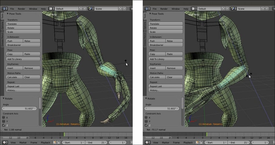
The effect of the rotation of the forearm bone on the upper arm b-bone and skinned mesh
The effect acts on the shin as well, by rotating the foot.L bone on the global z axis:

The same effect obtained on the calf b-bone by rotating the foot on its local y axis
Also, the same effect acts on the thigh by rotating the calf.L bone:

The same effect obtained on the leg b-bone by rotating the calf
Note that the Gidiosaurus is a digitigrade biped humanoid: the bones that, from our plantigrade point of view, look like the foot are actually the toes, while the almost vertical structure that we would call an ankle is the real foot (this is a very common condition among the majority of the terrestrial animals, both still alive and extinct).
Getting ready
In this first recipe, we are going to build by hands the basic rig, which is the skeleton made only by the deforming bones.
However, first, let's prepare a bit the file to be worked:
- Start Blender and open the
Gidiosaurus_unwrap_final.blendfile. - Disable the Textured Solid and Backface Culling items in the 3D view Properties sidepanel, join the 3D window with the UV/Image Editor window, and click on the 11th scene layer to have only the Gidiosaurus mesh visible in the viewport.
- Go to the Object window under the Display subpanel and enable the Wire item. This will be useful in the process in order to have an idea of the mesh topology when in Object Mode and Solid viewport shading mode. However, for the moment, press the Z key to go in the Wireframe viewport shading mode.
- Press 1 on the numpad to go in the Front view, and press 5 on the numpad again to switch to the Ortho view.
- Save the file as
Gidiosaurus_rig_from_scratch_start.blend.
Let's start:
- Be sure that the 3D Cursor is at the origin pivot point of the Gidiosaurus mesh. Put the mouse pointer in the 3D view, press Shift + A, and in the Add pop-up menu, select Armature | Single Bone:
Adding the first Armature's bone
- Press Tab to go into Edit Mode and select the whole bone by right-clicking on its central part; move the bone upwards to the Gidiosaurus's hips area (G | Z | Enter or left-click to confirm), and then go in the Side view (3 key on the numpad) and center its position by moving it on the y axis:
Positioning the bone in Edit Mode
- Right-click on the Head of the bone to select it and by pressing G to move it, scale the bone size to fit the pelvis area:
Scaling the bone in Edit Mode
- Go to the Item subpanel under the 3D view Properties sidepanel, or in the Bone window under the main Properties panel to the right-hand side of the screen, and rename Bone (default name) as hips:
Renaming the bone
- Press Z to go in the Solid viewport shading mode, and then go to the Object Data window and enable the X-Ray item under the Display subpanel.
- With the tip of the bone selected (the Head), press the E key to extrude it. By this process, and by following the wire topology visible on the mesh as a guide, go upwards to build the Gidiosaurus spine (2 bones), chest (1 bone), and neck (1 bone); as much as possible, try to place the Heads (the tips/joints) of the bones aligned with the transversal edge-loops on the mesh's articulation:
Extruding the bone to build the spine
- Go again to the Object Data window under the Display subpanel, and enable the Names item (in the following screenshot, all the bones have been selected just to highlight them and their respective names). As you can see in the screenshot, the extruded bones get their names from the previous one, so we have hips, then hips.001, hips.002, and so on:
The bones' names
- Select the hips.001 bone and rename it spine.001; select the hips.002 bone and rename it spine.002.
- Select the hips.003 bone and rename it chest; select the hips.004 bone and rename it neck.
- Select the tip of the neck bone and extrude it; rename the new bone (neck.001) as head:
The renamed bones and the head bone
So, now we have built the spine - neck – head part of the Armature; actually, one thing is still missing: the bone to animate the mandible.
- Press Tab to get out of Edit Mode. In the Side view, enable the 15th scene layer on the 3D viewport toolbar, in order to show the Empty_rot_mand object; select it and press Shift + S to call the Snap pop-up menu. Then, select the Cursor to Selected item.
- Reselect the Armature and go again into Edit Mode. Press Shift + A to add a new bone; move its Head to resize and fit it inside the mandible of the Gidiosaurus:
The mandible's bone
- Rename it mand and in the Bone window under the main Properties panel, in the Relations subpanel, click on the Parent slot to select the head item from the pop-up menu with the bones list. Leave the Connected item unchecked:
The Parent slot and the pop-up menu to select the parent bone
At this point, we can already see some particular setting to be applied to the bones.
- Go to the Object Data window under the Properties panel and in the Display subpanel, switch from the default Octahedral to the B-bone button:
The bones visualized as B-bones
- Press A to select all the bones, and then press Ctrl + Alt + S (or go to the Armature item in the window toolbar, and then go to Transform | Scale Bbone) and scale the B-bones to 0.200 (hold the Ctrl key to constrain the scaling values; the B-bones scaling works both in Edit Mode and Pose Mode).
- Select only the chest bone and scale it bigger to 2.500; select the head bone and scale it to 4.000:
The B-bones scaled for better visualization
- Go to the Object window and under the Display subpanel, click on the Maximum Draw Type slot (set to Textured by default) and switch it to Wire.
- Press Ctrl + Tab to switch the Armature directly from Edit Mode to Pose Mode. Right-click on the chest bone to select it and go to the Bone window under the main Properties panel; in the Deform subpanel, set Segments under the Curved Bones item to 3:
The chest B-bone with 3 curved segments
- Select the spine.002 and spine.001 bones and set Segments to 2. Select the neck bone and set Segments to 3.
- Select the Gidiosaurus mesh, go to the Object window, and disable the Wire item under the Display subpanel:
The rig so far
- Press Ctrl + Tab to go out of the Pose Mode, and then Shift + S | Cursor to Selected to put the 3D Cursor at the rig/mesh/center of the scene pivot point.
- Press Tab to go into Edit Mode and press the 1 key on the numpad to go in the Front view; go to the Object Data window, under the Display subpanel, and switch back from B-bone to Octahedral (even if the visualization mode is different, the bones set as B-Splines still keep their curved properties in Pose Mode).
- Press Shift + A to add a new bone at the cursor position. Move and resize it to put it as the clavicle bone—almost horizontal and slightly backward oriented, on the left-hand side of the rig. Rename it shoulder.L and in the Parent slot under the Relations subpanel, select the chest item:
The shoulder.L bone
- In the Front view, select the Head of the shoulder.L bone and extrude it 3 times to build the bones for arm, forearm, and hand:
Extruding the shoulder.L bone to obtain the skeleton's bones for the arm
- Now, exit Edit Mode and right-click to select the Gidiosaurus mesh; enter Edit Mode, select one or more edge-loops at the elbow level, and press Shift + S | Cursor to Selected.
- Get out of Edit Mode, select the Armature; go into Edit Mode, select the joint between the arm and forearm bones and press Shift + S | Selection to Cursor:
Placing the elbow joint
- This is the easiest way to correctly align the rig joints with the mesh edge-loops. Do the same for the joint of the wrist and the bone of the hand; rename the bones as arm.L, forearm.L, and hand.L:
Fixing the position of the wrist joint and hand's bone
- Select the hand.L bone and use Shift + D to duplicate it; scale it smaller (S | 0.600 | Enter), rename it palm_01.L, and move it above the joining of the palm with the thumb. Use Shift + D to duplicate it 2 more times and move the new bones above the joining of the other two fingers; rename them palm_02.L and palm_03.L.
- Use Shift to select the three palm bones and, as the last one, the hand.L bone; press Ctrl + P | Keep Offset to parent them (not connected) to the latter one:
Adding the palm bones
- Select (individually) the Heads of each palm bones and extrude the bones for the fingers; center their joints with the 3D Cursor/Snap menu method and rename them properly (thumb, index, and middle):
The bones for the fingers
- Again with the 3D Cursor at the rig pivot point, add a new bone and shape it to fit inside the left thigh, the Tail at the top, close to the hips bone, and the Head at the knee location; select it and use Shift to select the hips bone, and then press Ctrl + P | Keep Offset. Extrude the bone's Head three times to build the leg – foot skeleton.
- Extrude also the bones for the toes and repeat the previously described process to center the joints, and then rename all the new bones (leg, calf, foot, toe inn, and ext):
The bones for the leg and toes
In the preceding screenshots, you can see that we have hidden the talons vertices in Edit Mode (H key), in order to have the possibility to easily select the last edge-loops on fingers and toes.
- Save the file as
Gidiosaurus_rig_from_scratch_01.blend.
Now that we have completed the main body rigging system, it's time to build the rig for eyes, eyelids, and tongue:
- Get out of Edit Mode and select the Eyes item in the Outliner; press the dot (.) key on the numpad to center the view on the selected object, the Z key to go in Wireframe viewport shading mode, and Tab to go into Edit Mode.
- Press the A key to select all the eye vertices and then box-deselect (the B key and the middle mouse button) the vertices of the right eye; use Shift + S to call the Snap pop-up menu and select the Cursor to Selected item to place the 3D Cursor at the center of the left eye mesh:
Placing the 3D Cursor at the center of the selected vertices
- Get out of Edit Mode, press the 3 key on the numpad to go in the Side view and reselect the Armature item in the Outliner; press Tab to go into Edit Mode, and then use Shift + A to add a new bone at the cursor position. Press G to grab the already selected Head of the new bone and move it close to the center of the eye to resize it smaller.
- Get out of Edit Mode and select the Eyes item; enter Edit Mode and deselect all the vertices except for the external last iris edge-loop. Then, press Shift + S | Cursor to Selected and get out of Edit Mode.
- Again, select the Armature, go into Edit Mode, be sure that the Head of the new bone is still selected, and press Shift + S | Selection to Cursor:
Placing the bone's head at the iris center location
- Rename the new bone as eye.L and in the Relations subpanel under the Bone window, parent it to the head bone (not Connected), or use Shift to select the eye.L and head bones and press Ctrl + P | Keep Offset.
- Now, select the Tail of the eye.L bone and press Shift + S | Cursor to Selected to put the 3D Cursor on it, and then press the period (.) key to switch the Pivot Point around the 3D Cursor; select the whole eye.L bone and use Shift + D to duplicate it, and soon after, click with the right mouse button to leave the duplicated bone untouched; rotate it 10 degrees clockwise on the cursor position (Shift + D | right-click | R | X | 10 | Enter).
- Rename the new bone as eyelid_upper.L.
- Reselect the whole eye.L bone and repeat the duplication procedure; rotate the new duplicate 10 degrees counterclockwise (Shift + D | right-click | R | X | -10 | Enter).
- Rename the new bone as eyelid_bottom.L (in the following screenshot, all the three new bones—eyelid_upper.L, eye.L, and eyelid_bottom.L—have been selected just to enhance their visibility):
The bones for the eye and eyelids
- Now, duplicate the head bone, resize it smaller, and move it to the joining of the tongue with the inner mouth; rename it from head.001 to tongue.001 and in the Relations subpanel, change its parenting from neck to mand.
- Select the Head of the tongue.001 bone and press the E key to extrude 4 new bones:
The tongue bones
- Rename them accordingly, and then use Shift to select from the tongue.001 to tongue.005 bones and press Ctrl + R; move the mouse pointer horizontally to roll them on their y axis by 180° (hold Ctrl to constrain the rolling to intervals of 5 degrees; alternatively, the roll value can also be set by typing it in the Roll button in the Transform subpanel under the 3D viewport Properties sidepanel).
At this point, the basic rig building process is almost done, even if it is only for the left-half part of the mesh:
- Get out of Edit Mode and press Shift + S | Cursor to Selected to place the 3D Cursor at the median pivot point of the Armature.
- Go back into Edit Mode, select only the left-half part bones and not the median ones (meaning: leave the hips, spine, neck, head, mouth, and tongue bones unselected), press Shift + D to duplicate them, and then right-click with the mouse button; press Ctrl + M, then the X key to mirror the duplicated bones on the x axis, in order to build the missing right-half part of the rig:
Mirroring the duplicated bones on the x axis
- With the duplicated bones still selected, go to the 3D window toolbar and click on the Armature item; in the pop-up menu, select the Flip Names item to automatically rename them with the correct .R suffix:
Renaming the suffix of the duplicated bones
As a very last thing for this recipe, we must verify that the alignment of the bones, especially the last duplicated ones, is correct and, just in case, recalculate the roll rotation, that is, the rotation around the y axis of the bone itself.
- In the Object Data window, under the Display subpanel, check the Axes item to make the bones orientation axes visible (only in Edit Mode and Pose Mode) in the 3D view.
- Select all the bones and press Ctrl + N to recalculate the rolling of all of them; in the Recalculate Roll pop-up menu, there are several different options: because basically the z axis of the bones must match from the left to the right side of the whole rig, with the Armature (and the mesh) oriented along the y global axis, as in our Gidiosaurus case, the first top item, Local X Tangent, can be a good start.
By the way, it is good practice to not trust this automated procedure alone, because sometimes it can give inconsistent results; so, do the following:
- After the recalculation, check that the axes of each bone are actually correctly orientated in a consistent way; effectively, there are some bones that didn't get consistently oriented, meaning that their x and z local axes are oriented differently from the other bones.
- In this case, select the incorrectly oriented bone, press Ctrl + R, and move the mouse to change the rolling; press the Ctrl key to constrain the rolling to intervals of 5 degrees. Alternatively, select the wrong bones, and then use Shift to select one bone that is correctly oriented and press Ctrl + N | Active Bone to copy the rolling from the last selected bone.
By enabling the X-Axis Mirror item in the Armature Options tab under the Tool Shelf, you can recalculate only the bones of one side; the other side bones will follow automatically.
If you want to make sure the bones' orientations are correct and everything is going to work in animation, just go into Pose Mode and rotate one bone, for example leg.L, and then click on the Copies the current pose of the selected bones to copy/paste buffer button (Ctrl + C), which is the first left one of the last three buttons to the right-hand side of the viewport toolbar; then, select the symmetrical bone, leg.R, and click on the last right button to paste the flipped pose (Ctrl + Shift + V); if the leg.R bone rotates correctly, then the orientation is OK:
Recalculating the roll of incorrectly oriented bones
- Now, go to the Object Data window under the main Properties panel and under Display, switch again the bones visualization from Octahedral to B-bone; select the bones and by pressing Ctrl + Alt + S, scale the B-bones smaller or bigger, depending on the visual effect you want to obtain:
The almost completed Armature in B-bones visualization
- Press Ctrl + Tab to pass directly from Edit Mode to Pose Mode and select the forearm.L bone; in the Deform subpanel under the Properties panel, set the Segments for the Curved Bones to 12, and then set the Ease In and Ease Out values to 0.000.
- Repeat this for the forearm.R bone and also for the calf.L and calf.R bones; repeat also for the arm.L, arm.R, leg.L, and leg.R bones.
In the following screenshot, all the eight B-bones have been selected to make them more visible. By the way, the highlighted leg.R bone is the active one and shows the Curved Bones setting in the highlighted Deform subpanel to the right-hand side of the screen.
The Segments setting for the leg bone
- Select the toe_inn_02.L bone and in the Deform subpanel under the Properties panel, set the Segments to 6 and leave the Ease In and Ease Out values to 1.000.
- Repeat this for the toe_ext_02.L bone; then, do the same also to the toe_inn_02.R and toe_ext_02.R bones.
- Select the toe_inn_01.L bone and set the Segments to 3; leave the Ease In and Ease Out values to 1.000.
- Repeat for the toe_ext_01.L bone; then, do the same also to the toe_inn_01.R and toe_ext_01.R bones:
The Segments setting for the toes bones
- Save the file.
Although it's often a really time consuming task, the handmade rigging is quite self-explicative; it is, however, better to explain some of the concepts behind this.
The proper renaming of the bones is important, considering that each deforming bone will affect a vertex group sharing the same name on the mesh; although in some cases, as for the tongue bones, the bone naming process can be automated in some way, usually it is better to spend time in giving meaningful names to each bone, in order to avoid mistakes in the following skinning process.
It's also very important to build the hierarchy of the bones so that a bone at a higher level can lead all of the children bones, as it would be in a real skeleton (that is, for example, the hand bone leads all the fingers bones, the forearm bone leads the hand bone, and so on).
Parenting a bone and then obtaining the others by extruding and/or duplicating simplifies the work because an extruded bone is automatically parented to the bone it has been extruded from, and a duplicated bone obviously inherits the parenting of the original one; in the case of the tongue.001 bone, extruding the others has given us a chain with bones automatically parented and named as tongue.002, tongue.003, tongue.004, and tongue.005.
B-bones are both a visualization mode for the bones and a way of working; B-bones, in fact, can work inside a chain as splines, which means that the bones are curved according to the number of Segments and the values of the Ease In and Ease Out items. For the bones of the arms and legs, we have set the Ease In and Ease Out values to 0.000 (default is 1.000; maximum is 2.000), in order to have the B-bones rotating only on their y axis but remaining straight along their length, and hence, mimic the twisting by not only the rotation (pronation and supination of the lower arm) of both the Ulna-Radius and Tibia-Fibula articulation complexes, but also the (limited) rotation of Femur and Humerus.
In some way, B-bones can work as a kind of simulation for a very basic muscle system; in the following screenshot, you can see their effect on the skinned mesh for the forearm by rotating the hand.L bone on the local y axis (to enhance the visibility of the mesh surface's modifications, the wireframe over solid drawing item has been enabled in the Display subpanel under the Object window):
The effect of the rotation of the hand bone on the forearm B-bone and skinned mesh
Here is the effect of the rotation of the forearm.L bone on the Gidiosaurus high arm:
The effect of the rotation of the forearm bone on the upper arm b-bone and skinned mesh
The effect acts on the shin as well, by rotating the foot.L bone on the global z axis:
The same effect obtained on the calf b-bone by rotating the foot on its local y axis
Also, the same effect acts on the thigh by rotating the calf.L bone:
The same effect obtained on the leg b-bone by rotating the calf
Note that the Gidiosaurus is a digitigrade biped humanoid: the bones that, from our plantigrade point of view, look like the foot are actually the toes, while the almost vertical structure that we would call an ankle is the real foot (this is a very common condition among the majority of the terrestrial animals, both still alive and extinct).
How to do it…
Let's start:
- Be sure that the 3D Cursor is at the origin pivot point of the Gidiosaurus mesh. Put the mouse pointer in the 3D view, press Shift + A, and in the Add pop-up menu, select Armature | Single Bone:
Adding the first Armature's bone
- Press Tab to go into Edit Mode and select the whole bone by right-clicking on its central part; move the bone upwards to the Gidiosaurus's hips area (G | Z | Enter or left-click to confirm), and then go in the Side view (3 key on the numpad) and center its position by moving it on the y axis:
Positioning the bone in Edit Mode
- Right-click on the Head of the bone to select it and by pressing G to move it, scale the bone size to fit the pelvis area:
Scaling the bone in Edit Mode
- Go to the Item subpanel under the 3D view Properties sidepanel, or in the Bone window under the main Properties panel to the right-hand side of the screen, and rename Bone (default name) as hips:
Renaming the bone
- Press Z to go in the Solid viewport shading mode, and then go to the Object Data window and enable the X-Ray item under the Display subpanel.
- With the tip of the bone selected (the Head), press the E key to extrude it. By this process, and by following the wire topology visible on the mesh as a guide, go upwards to build the Gidiosaurus spine (2 bones), chest (1 bone), and neck (1 bone); as much as possible, try to place the Heads (the tips/joints) of the bones aligned with the transversal edge-loops on the mesh's articulation:
Extruding the bone to build the spine
- Go again to the Object Data window under the Display subpanel, and enable the Names item (in the following screenshot, all the bones have been selected just to highlight them and their respective names). As you can see in the screenshot, the extruded bones get their names from the previous one, so we have hips, then hips.001, hips.002, and so on:
The bones' names
- Select the hips.001 bone and rename it spine.001; select the hips.002 bone and rename it spine.002.
- Select the hips.003 bone and rename it chest; select the hips.004 bone and rename it neck.
- Select the tip of the neck bone and extrude it; rename the new bone (neck.001) as head:
The renamed bones and the head bone
So, now we have built the spine - neck – head part of the Armature; actually, one thing is still missing: the bone to animate the mandible.
- Press Tab to get out of Edit Mode. In the Side view, enable the 15th scene layer on the 3D viewport toolbar, in order to show the Empty_rot_mand object; select it and press Shift + S to call the Snap pop-up menu. Then, select the Cursor to Selected item.
- Reselect the Armature and go again into Edit Mode. Press Shift + A to add a new bone; move its Head to resize and fit it inside the mandible of the Gidiosaurus:
The mandible's bone
- Rename it mand and in the Bone window under the main Properties panel, in the Relations subpanel, click on the Parent slot to select the head item from the pop-up menu with the bones list. Leave the Connected item unchecked:
The Parent slot and the pop-up menu to select the parent bone
At this point, we can already see some particular setting to be applied to the bones.
- Go to the Object Data window under the Properties panel and in the Display subpanel, switch from the default Octahedral to the B-bone button:
The bones visualized as B-bones
- Press A to select all the bones, and then press Ctrl + Alt + S (or go to the Armature item in the window toolbar, and then go to Transform | Scale Bbone) and scale the B-bones to 0.200 (hold the Ctrl key to constrain the scaling values; the B-bones scaling works both in Edit Mode and Pose Mode).
- Select only the chest bone and scale it bigger to 2.500; select the head bone and scale it to 4.000:
The B-bones scaled for better visualization
- Go to the Object window and under the Display subpanel, click on the Maximum Draw Type slot (set to Textured by default) and switch it to Wire.
- Press Ctrl + Tab to switch the Armature directly from Edit Mode to Pose Mode. Right-click on the chest bone to select it and go to the Bone window under the main Properties panel; in the Deform subpanel, set Segments under the Curved Bones item to 3:
The chest B-bone with 3 curved segments
- Select the spine.002 and spine.001 bones and set Segments to 2. Select the neck bone and set Segments to 3.
- Select the Gidiosaurus mesh, go to the Object window, and disable the Wire item under the Display subpanel:
The rig so far
- Press Ctrl + Tab to go out of the Pose Mode, and then Shift + S | Cursor to Selected to put the 3D Cursor at the rig/mesh/center of the scene pivot point.
- Press Tab to go into Edit Mode and press the 1 key on the numpad to go in the Front view; go to the Object Data window, under the Display subpanel, and switch back from B-bone to Octahedral (even if the visualization mode is different, the bones set as B-Splines still keep their curved properties in Pose Mode).
- Press Shift + A to add a new bone at the cursor position. Move and resize it to put it as the clavicle bone—almost horizontal and slightly backward oriented, on the left-hand side of the rig. Rename it shoulder.L and in the Parent slot under the Relations subpanel, select the chest item:
The shoulder.L bone
- In the Front view, select the Head of the shoulder.L bone and extrude it 3 times to build the bones for arm, forearm, and hand:
Extruding the shoulder.L bone to obtain the skeleton's bones for the arm
- Now, exit Edit Mode and right-click to select the Gidiosaurus mesh; enter Edit Mode, select one or more edge-loops at the elbow level, and press Shift + S | Cursor to Selected.
- Get out of Edit Mode, select the Armature; go into Edit Mode, select the joint between the arm and forearm bones and press Shift + S | Selection to Cursor:
Placing the elbow joint
- This is the easiest way to correctly align the rig joints with the mesh edge-loops. Do the same for the joint of the wrist and the bone of the hand; rename the bones as arm.L, forearm.L, and hand.L:
Fixing the position of the wrist joint and hand's bone
- Select the hand.L bone and use Shift + D to duplicate it; scale it smaller (S | 0.600 | Enter), rename it palm_01.L, and move it above the joining of the palm with the thumb. Use Shift + D to duplicate it 2 more times and move the new bones above the joining of the other two fingers; rename them palm_02.L and palm_03.L.
- Use Shift to select the three palm bones and, as the last one, the hand.L bone; press Ctrl + P | Keep Offset to parent them (not connected) to the latter one:
Adding the palm bones
- Select (individually) the Heads of each palm bones and extrude the bones for the fingers; center their joints with the 3D Cursor/Snap menu method and rename them properly (thumb, index, and middle):
The bones for the fingers
- Again with the 3D Cursor at the rig pivot point, add a new bone and shape it to fit inside the left thigh, the Tail at the top, close to the hips bone, and the Head at the knee location; select it and use Shift to select the hips bone, and then press Ctrl + P | Keep Offset. Extrude the bone's Head three times to build the leg – foot skeleton.
- Extrude also the bones for the toes and repeat the previously described process to center the joints, and then rename all the new bones (leg, calf, foot, toe inn, and ext):
The bones for the leg and toes
In the preceding screenshots, you can see that we have hidden the talons vertices in Edit Mode (H key), in order to have the possibility to easily select the last edge-loops on fingers and toes.
- Save the file as
Gidiosaurus_rig_from_scratch_01.blend.
Now that we have completed the main body rigging system, it's time to build the rig for eyes, eyelids, and tongue:
- Get out of Edit Mode and select the Eyes item in the Outliner; press the dot (.) key on the numpad to center the view on the selected object, the Z key to go in Wireframe viewport shading mode, and Tab to go into Edit Mode.
- Press the A key to select all the eye vertices and then box-deselect (the B key and the middle mouse button) the vertices of the right eye; use Shift + S to call the Snap pop-up menu and select the Cursor to Selected item to place the 3D Cursor at the center of the left eye mesh:
Placing the 3D Cursor at the center of the selected vertices
- Get out of Edit Mode, press the 3 key on the numpad to go in the Side view and reselect the Armature item in the Outliner; press Tab to go into Edit Mode, and then use Shift + A to add a new bone at the cursor position. Press G to grab the already selected Head of the new bone and move it close to the center of the eye to resize it smaller.
- Get out of Edit Mode and select the Eyes item; enter Edit Mode and deselect all the vertices except for the external last iris edge-loop. Then, press Shift + S | Cursor to Selected and get out of Edit Mode.
- Again, select the Armature, go into Edit Mode, be sure that the Head of the new bone is still selected, and press Shift + S | Selection to Cursor:
Placing the bone's head at the iris center location
- Rename the new bone as eye.L and in the Relations subpanel under the Bone window, parent it to the head bone (not Connected), or use Shift to select the eye.L and head bones and press Ctrl + P | Keep Offset.
- Now, select the Tail of the eye.L bone and press Shift + S | Cursor to Selected to put the 3D Cursor on it, and then press the period (.) key to switch the Pivot Point around the 3D Cursor; select the whole eye.L bone and use Shift + D to duplicate it, and soon after, click with the right mouse button to leave the duplicated bone untouched; rotate it 10 degrees clockwise on the cursor position (Shift + D | right-click | R | X | 10 | Enter).
- Rename the new bone as eyelid_upper.L.
- Reselect the whole eye.L bone and repeat the duplication procedure; rotate the new duplicate 10 degrees counterclockwise (Shift + D | right-click | R | X | -10 | Enter).
- Rename the new bone as eyelid_bottom.L (in the following screenshot, all the three new bones—eyelid_upper.L, eye.L, and eyelid_bottom.L—have been selected just to enhance their visibility):
The bones for the eye and eyelids
- Now, duplicate the head bone, resize it smaller, and move it to the joining of the tongue with the inner mouth; rename it from head.001 to tongue.001 and in the Relations subpanel, change its parenting from neck to mand.
- Select the Head of the tongue.001 bone and press the E key to extrude 4 new bones:
The tongue bones
- Rename them accordingly, and then use Shift to select from the tongue.001 to tongue.005 bones and press Ctrl + R; move the mouse pointer horizontally to roll them on their y axis by 180° (hold Ctrl to constrain the rolling to intervals of 5 degrees; alternatively, the roll value can also be set by typing it in the Roll button in the Transform subpanel under the 3D viewport Properties sidepanel).
At this point, the basic rig building process is almost done, even if it is only for the left-half part of the mesh:
- Get out of Edit Mode and press Shift + S | Cursor to Selected to place the 3D Cursor at the median pivot point of the Armature.
- Go back into Edit Mode, select only the left-half part bones and not the median ones (meaning: leave the hips, spine, neck, head, mouth, and tongue bones unselected), press Shift + D to duplicate them, and then right-click with the mouse button; press Ctrl + M, then the X key to mirror the duplicated bones on the x axis, in order to build the missing right-half part of the rig:
Mirroring the duplicated bones on the x axis
- With the duplicated bones still selected, go to the 3D window toolbar and click on the Armature item; in the pop-up menu, select the Flip Names item to automatically rename them with the correct .R suffix:
Renaming the suffix of the duplicated bones
As a very last thing for this recipe, we must verify that the alignment of the bones, especially the last duplicated ones, is correct and, just in case, recalculate the roll rotation, that is, the rotation around the y axis of the bone itself.
- In the Object Data window, under the Display subpanel, check the Axes item to make the bones orientation axes visible (only in Edit Mode and Pose Mode) in the 3D view.
- Select all the bones and press Ctrl + N to recalculate the rolling of all of them; in the Recalculate Roll pop-up menu, there are several different options: because basically the z axis of the bones must match from the left to the right side of the whole rig, with the Armature (and the mesh) oriented along the y global axis, as in our Gidiosaurus case, the first top item, Local X Tangent, can be a good start.
By the way, it is good practice to not trust this automated procedure alone, because sometimes it can give inconsistent results; so, do the following:
- After the recalculation, check that the axes of each bone are actually correctly orientated in a consistent way; effectively, there are some bones that didn't get consistently oriented, meaning that their x and z local axes are oriented differently from the other bones.
- In this case, select the incorrectly oriented bone, press Ctrl + R, and move the mouse to change the rolling; press the Ctrl key to constrain the rolling to intervals of 5 degrees. Alternatively, select the wrong bones, and then use Shift to select one bone that is correctly oriented and press Ctrl + N | Active Bone to copy the rolling from the last selected bone.
By enabling the X-Axis Mirror item in the Armature Options tab under the Tool Shelf, you can recalculate only the bones of one side; the other side bones will follow automatically.
If you want to make sure the bones' orientations are correct and everything is going to work in animation, just go into Pose Mode and rotate one bone, for example leg.L, and then click on the Copies the current pose of the selected bones to copy/paste buffer button (Ctrl + C), which is the first left one of the last three buttons to the right-hand side of the viewport toolbar; then, select the symmetrical bone, leg.R, and click on the last right button to paste the flipped pose (Ctrl + Shift + V); if the leg.R bone rotates correctly, then the orientation is OK:
Recalculating the roll of incorrectly oriented bones
- Now, go to the Object Data window under the main Properties panel and under Display, switch again the bones visualization from Octahedral to B-bone; select the bones and by pressing Ctrl + Alt + S, scale the B-bones smaller or bigger, depending on the visual effect you want to obtain:
The almost completed Armature in B-bones visualization
- Press Ctrl + Tab to pass directly from Edit Mode to Pose Mode and select the forearm.L bone; in the Deform subpanel under the Properties panel, set the Segments for the Curved Bones to 12, and then set the Ease In and Ease Out values to 0.000.
- Repeat this for the forearm.R bone and also for the calf.L and calf.R bones; repeat also for the arm.L, arm.R, leg.L, and leg.R bones.
In the following screenshot, all the eight B-bones have been selected to make them more visible. By the way, the highlighted leg.R bone is the active one and shows the Curved Bones setting in the highlighted Deform subpanel to the right-hand side of the screen.
The Segments setting for the leg bone
- Select the toe_inn_02.L bone and in the Deform subpanel under the Properties panel, set the Segments to 6 and leave the Ease In and Ease Out values to 1.000.
- Repeat this for the toe_ext_02.L bone; then, do the same also to the toe_inn_02.R and toe_ext_02.R bones.
- Select the toe_inn_01.L bone and set the Segments to 3; leave the Ease In and Ease Out values to 1.000.
- Repeat for the toe_ext_01.L bone; then, do the same also to the toe_inn_01.R and toe_ext_01.R bones:
The Segments setting for the toes bones
- Save the file.
Although it's often a really time consuming task, the handmade rigging is quite self-explicative; it is, however, better to explain some of the concepts behind this.
The proper renaming of the bones is important, considering that each deforming bone will affect a vertex group sharing the same name on the mesh; although in some cases, as for the tongue bones, the bone naming process can be automated in some way, usually it is better to spend time in giving meaningful names to each bone, in order to avoid mistakes in the following skinning process.
It's also very important to build the hierarchy of the bones so that a bone at a higher level can lead all of the children bones, as it would be in a real skeleton (that is, for example, the hand bone leads all the fingers bones, the forearm bone leads the hand bone, and so on).
Parenting a bone and then obtaining the others by extruding and/or duplicating simplifies the work because an extruded bone is automatically parented to the bone it has been extruded from, and a duplicated bone obviously inherits the parenting of the original one; in the case of the tongue.001 bone, extruding the others has given us a chain with bones automatically parented and named as tongue.002, tongue.003, tongue.004, and tongue.005.
B-bones are both a visualization mode for the bones and a way of working; B-bones, in fact, can work inside a chain as splines, which means that the bones are curved according to the number of Segments and the values of the Ease In and Ease Out items. For the bones of the arms and legs, we have set the Ease In and Ease Out values to 0.000 (default is 1.000; maximum is 2.000), in order to have the B-bones rotating only on their y axis but remaining straight along their length, and hence, mimic the twisting by not only the rotation (pronation and supination of the lower arm) of both the Ulna-Radius and Tibia-Fibula articulation complexes, but also the (limited) rotation of Femur and Humerus.
In some way, B-bones can work as a kind of simulation for a very basic muscle system; in the following screenshot, you can see their effect on the skinned mesh for the forearm by rotating the hand.L bone on the local y axis (to enhance the visibility of the mesh surface's modifications, the wireframe over solid drawing item has been enabled in the Display subpanel under the Object window):
The effect of the rotation of the hand bone on the forearm B-bone and skinned mesh
Here is the effect of the rotation of the forearm.L bone on the Gidiosaurus high arm:
The effect of the rotation of the forearm bone on the upper arm b-bone and skinned mesh
The effect acts on the shin as well, by rotating the foot.L bone on the global z axis:
The same effect obtained on the calf b-bone by rotating the foot on its local y axis
Also, the same effect acts on the thigh by rotating the calf.L bone:
The same effect obtained on the leg b-bone by rotating the calf
Note that the Gidiosaurus is a digitigrade biped humanoid: the bones that, from our plantigrade point of view, look like the foot are actually the toes, while the almost vertical structure that we would call an ankle is the real foot (this is a very common condition among the majority of the terrestrial animals, both still alive and extinct).
Building the rig for the secondary parts
Now that we have completed the main body rigging system, it's time to build the rig for eyes, eyelids, and tongue:
- Get out of Edit Mode and select the Eyes item in the Outliner; press the dot (.) key on the numpad to center the view on the selected object, the Z key to go in Wireframe viewport shading mode, and Tab to go into Edit Mode.
- Press the A key to select all the eye vertices and then box-deselect (the B key and the middle mouse button) the vertices of the right eye; use Shift + S to call the Snap pop-up menu and select the Cursor to Selected item to place the 3D Cursor at the center of the left eye mesh:
Placing the 3D Cursor at the center of the selected vertices
- Get out of Edit Mode, press the 3 key on the numpad to go in the Side view and reselect the Armature item in the Outliner; press Tab to go into Edit Mode, and then use Shift + A to add a new bone at the cursor position. Press G to grab the already selected Head of the new bone and move it close to the center of the eye to resize it smaller.
- Get out of Edit Mode and select the Eyes item; enter Edit Mode and deselect all the vertices except for the external last iris edge-loop. Then, press Shift + S | Cursor to Selected and get out of Edit Mode.
- Again, select the Armature, go into Edit Mode, be sure that the Head of the new bone is still selected, and press Shift + S | Selection to Cursor:
Placing the bone's head at the iris center location
- Rename the new bone as eye.L and in the Relations subpanel under the Bone window, parent it to the head bone (not Connected), or use Shift to select the eye.L and head bones and press Ctrl + P | Keep Offset.
- Now, select the Tail of the eye.L bone and press Shift + S | Cursor to Selected to put the 3D Cursor on it, and then press the period (.) key to switch the Pivot Point around the 3D Cursor; select the whole eye.L bone and use Shift + D to duplicate it, and soon after, click with the right mouse button to leave the duplicated bone untouched; rotate it 10 degrees clockwise on the cursor position (Shift + D | right-click | R | X | 10 | Enter).
- Rename the new bone as eyelid_upper.L.
- Reselect the whole eye.L bone and repeat the duplication procedure; rotate the new duplicate 10 degrees counterclockwise (Shift + D | right-click | R | X | -10 | Enter).
- Rename the new bone as eyelid_bottom.L (in the following screenshot, all the three new bones—eyelid_upper.L, eye.L, and eyelid_bottom.L—have been selected just to enhance their visibility):
The bones for the eye and eyelids
- Now, duplicate the head bone, resize it smaller, and move it to the joining of the tongue with the inner mouth; rename it from head.001 to tongue.001 and in the Relations subpanel, change its parenting from neck to mand.
- Select the Head of the tongue.001 bone and press the E key to extrude 4 new bones:
The tongue bones
- Rename them accordingly, and then use Shift to select from the tongue.001 to tongue.005 bones and press Ctrl + R; move the mouse pointer horizontally to roll them on their y axis by 180° (hold Ctrl to constrain the rolling to intervals of 5 degrees; alternatively, the roll value can also be set by typing it in the Roll button in the Transform subpanel under the 3D viewport Properties sidepanel).
At this point, the basic rig building process is almost done, even if it is only for the left-half part of the mesh:
- Get out of Edit Mode and press Shift + S | Cursor to Selected to place the 3D Cursor at the median pivot point of the Armature.
- Go back into Edit Mode, select only the left-half part bones and not the median ones (meaning: leave the hips, spine, neck, head, mouth, and tongue bones unselected), press Shift + D to duplicate them, and then right-click with the mouse button; press Ctrl + M, then the X key to mirror the duplicated bones on the x axis, in order to build the missing right-half part of the rig:
Mirroring the duplicated bones on the x axis
- With the duplicated bones still selected, go to the 3D window toolbar and click on the Armature item; in the pop-up menu, select the Flip Names item to automatically rename them with the correct .R suffix:
Renaming the suffix of the duplicated bones
As a very last thing for this recipe, we must verify that the alignment of the bones, especially the last duplicated ones, is correct and, just in case, recalculate the roll rotation, that is, the rotation around the y axis of the bone itself.
- In the Object Data window, under the Display subpanel, check the Axes item to make the bones orientation axes visible (only in Edit Mode and Pose Mode) in the 3D view.
- Select all the bones and press Ctrl + N to recalculate the rolling of all of them; in the Recalculate Roll pop-up menu, there are several different options: because basically the z axis of the bones must match from the left to the right side of the whole rig, with the Armature (and the mesh) oriented along the y global axis, as in our Gidiosaurus case, the first top item, Local X Tangent, can be a good start.
By the way, it is good practice to not trust this automated procedure alone, because sometimes it can give inconsistent results; so, do the following:
- After the recalculation, check that the axes of each bone are actually correctly orientated in a consistent way; effectively, there are some bones that didn't get consistently oriented, meaning that their x and z local axes are oriented differently from the other bones.
- In this case, select the incorrectly oriented bone, press Ctrl + R, and move the mouse to change the rolling; press the Ctrl key to constrain the rolling to intervals of 5 degrees. Alternatively, select the wrong bones, and then use Shift to select one bone that is correctly oriented and press Ctrl + N | Active Bone to copy the rolling from the last selected bone.
By enabling the X-Axis Mirror item in the Armature Options tab under the Tool Shelf, you can recalculate only the bones of one side; the other side bones will follow automatically.
If you want to make sure the bones' orientations are correct and everything is going to work in animation, just go into Pose Mode and rotate one bone, for example leg.L, and then click on the Copies the current pose of the selected bones to copy/paste buffer button (Ctrl + C), which is the first left one of the last three buttons to the right-hand side of the viewport toolbar; then, select the symmetrical bone, leg.R, and click on the last right button to paste the flipped pose (Ctrl + Shift + V); if the leg.R bone rotates correctly, then the orientation is OK:
Recalculating the roll of incorrectly oriented bones
- Now, go to the Object Data window under the main Properties panel and under Display, switch again the bones visualization from Octahedral to B-bone; select the bones and by pressing Ctrl + Alt + S, scale the B-bones smaller or bigger, depending on the visual effect you want to obtain:
The almost completed Armature in B-bones visualization
- Press Ctrl + Tab to pass directly from Edit Mode to Pose Mode and select the forearm.L bone; in the Deform subpanel under the Properties panel, set the Segments for the Curved Bones to 12, and then set the Ease In and Ease Out values to 0.000.
- Repeat this for the forearm.R bone and also for the calf.L and calf.R bones; repeat also for the arm.L, arm.R, leg.L, and leg.R bones.
In the following screenshot, all the eight B-bones have been selected to make them more visible. By the way, the highlighted leg.R bone is the active one and shows the Curved Bones setting in the highlighted Deform subpanel to the right-hand side of the screen.
The Segments setting for the leg bone
- Select the toe_inn_02.L bone and in the Deform subpanel under the Properties panel, set the Segments to 6 and leave the Ease In and Ease Out values to 1.000.
- Repeat this for the toe_ext_02.L bone; then, do the same also to the toe_inn_02.R and toe_ext_02.R bones.
- Select the toe_inn_01.L bone and set the Segments to 3; leave the Ease In and Ease Out values to 1.000.
- Repeat for the toe_ext_01.L bone; then, do the same also to the toe_inn_01.R and toe_ext_01.R bones:
The Segments setting for the toes bones
- Save the file.
Although it's often a really time consuming task, the handmade rigging is quite self-explicative; it is, however, better to explain some of the concepts behind this.
The proper renaming of the bones is important, considering that each deforming bone will affect a vertex group sharing the same name on the mesh; although in some cases, as for the tongue bones, the bone naming process can be automated in some way, usually it is better to spend time in giving meaningful names to each bone, in order to avoid mistakes in the following skinning process.
It's also very important to build the hierarchy of the bones so that a bone at a higher level can lead all of the children bones, as it would be in a real skeleton (that is, for example, the hand bone leads all the fingers bones, the forearm bone leads the hand bone, and so on).
Parenting a bone and then obtaining the others by extruding and/or duplicating simplifies the work because an extruded bone is automatically parented to the bone it has been extruded from, and a duplicated bone obviously inherits the parenting of the original one; in the case of the tongue.001 bone, extruding the others has given us a chain with bones automatically parented and named as tongue.002, tongue.003, tongue.004, and tongue.005.
B-bones are both a visualization mode for the bones and a way of working; B-bones, in fact, can work inside a chain as splines, which means that the bones are curved according to the number of Segments and the values of the Ease In and Ease Out items. For the bones of the arms and legs, we have set the Ease In and Ease Out values to 0.000 (default is 1.000; maximum is 2.000), in order to have the B-bones rotating only on their y axis but remaining straight along their length, and hence, mimic the twisting by not only the rotation (pronation and supination of the lower arm) of both the Ulna-Radius and Tibia-Fibula articulation complexes, but also the (limited) rotation of Femur and Humerus.
In some way, B-bones can work as a kind of simulation for a very basic muscle system; in the following screenshot, you can see their effect on the skinned mesh for the forearm by rotating the hand.L bone on the local y axis (to enhance the visibility of the mesh surface's modifications, the wireframe over solid drawing item has been enabled in the Display subpanel under the Object window):
The effect of the rotation of the hand bone on the forearm B-bone and skinned mesh
Here is the effect of the rotation of the forearm.L bone on the Gidiosaurus high arm:
The effect of the rotation of the forearm bone on the upper arm b-bone and skinned mesh
The effect acts on the shin as well, by rotating the foot.L bone on the global z axis:
The same effect obtained on the calf b-bone by rotating the foot on its local y axis
Also, the same effect acts on the thigh by rotating the calf.L bone:
The same effect obtained on the leg b-bone by rotating the calf
Note that the Gidiosaurus is a digitigrade biped humanoid: the bones that, from our plantigrade point of view, look like the foot are actually the toes, while the almost vertical structure that we would call an ankle is the real foot (this is a very common condition among the majority of the terrestrial animals, both still alive and extinct).
Completing the rig
At this point, the basic rig building process is almost done, even if it is only for the left-half part of the mesh:
- Get out of Edit Mode and press Shift + S | Cursor to Selected to place the 3D Cursor at the median pivot point of the Armature.
- Go back into Edit Mode, select only the left-half part bones and not the median ones (meaning: leave the hips, spine, neck, head, mouth, and tongue bones unselected), press Shift + D to duplicate them, and then right-click with the mouse button; press Ctrl + M, then the X key to mirror the duplicated bones on the x axis, in order to build the missing right-half part of the rig:
Mirroring the duplicated bones on the x axis
- With the duplicated bones still selected, go to the 3D window toolbar and click on the Armature item; in the pop-up menu, select the Flip Names item to automatically rename them with the correct .R suffix:
Renaming the suffix of the duplicated bones
As a very last thing for this recipe, we must verify that the alignment of the bones, especially the last duplicated ones, is correct and, just in case, recalculate the roll rotation, that is, the rotation around the y axis of the bone itself.
- In the Object Data window, under the Display subpanel, check the Axes item to make the bones orientation axes visible (only in Edit Mode and Pose Mode) in the 3D view.
- Select all the bones and press Ctrl + N to recalculate the rolling of all of them; in the Recalculate Roll pop-up menu, there are several different options: because basically the z axis of the bones must match from the left to the right side of the whole rig, with the Armature (and the mesh) oriented along the y global axis, as in our Gidiosaurus case, the first top item, Local X Tangent, can be a good start.
By the way, it is good practice to not trust this automated procedure alone, because sometimes it can give inconsistent results; so, do the following:
- After the recalculation, check that the axes of each bone are actually correctly orientated in a consistent way; effectively, there are some bones that didn't get consistently oriented, meaning that their x and z local axes are oriented differently from the other bones.
- In this case, select the incorrectly oriented bone, press Ctrl + R, and move the mouse to change the rolling; press the Ctrl key to constrain the rolling to intervals of 5 degrees. Alternatively, select the wrong bones, and then use Shift to select one bone that is correctly oriented and press Ctrl + N | Active Bone to copy the rolling from the last selected bone.
By enabling the X-Axis Mirror item in the Armature Options tab under the Tool Shelf, you can recalculate only the bones of one side; the other side bones will follow automatically.
If you want to make sure the bones' orientations are correct and everything is going to work in animation, just go into Pose Mode and rotate one bone, for example leg.L, and then click on the Copies the current pose of the selected bones to copy/paste buffer button (Ctrl + C), which is the first left one of the last three buttons to the right-hand side of the viewport toolbar; then, select the symmetrical bone, leg.R, and click on the last right button to paste the flipped pose (Ctrl + Shift + V); if the leg.R bone rotates correctly, then the orientation is OK:
Recalculating the roll of incorrectly oriented bones
- Now, go to the Object Data window under the main Properties panel and under Display, switch again the bones visualization from Octahedral to B-bone; select the bones and by pressing Ctrl + Alt + S, scale the B-bones smaller or bigger, depending on the visual effect you want to obtain:
The almost completed Armature in B-bones visualization
- Press Ctrl + Tab to pass directly from Edit Mode to Pose Mode and select the forearm.L bone; in the Deform subpanel under the Properties panel, set the Segments for the Curved Bones to 12, and then set the Ease In and Ease Out values to 0.000.
- Repeat this for the forearm.R bone and also for the calf.L and calf.R bones; repeat also for the arm.L, arm.R, leg.L, and leg.R bones.
In the following screenshot, all the eight B-bones have been selected to make them more visible. By the way, the highlighted leg.R bone is the active one and shows the Curved Bones setting in the highlighted Deform subpanel to the right-hand side of the screen.
The Segments setting for the leg bone
- Select the toe_inn_02.L bone and in the Deform subpanel under the Properties panel, set the Segments to 6 and leave the Ease In and Ease Out values to 1.000.
- Repeat this for the toe_ext_02.L bone; then, do the same also to the toe_inn_02.R and toe_ext_02.R bones.
- Select the toe_inn_01.L bone and set the Segments to 3; leave the Ease In and Ease Out values to 1.000.
- Repeat for the toe_ext_01.L bone; then, do the same also to the toe_inn_01.R and toe_ext_01.R bones:
The Segments setting for the toes bones
- Save the file.
Although it's often a really time consuming task, the handmade rigging is quite self-explicative; it is, however, better to explain some of the concepts behind this.
The proper renaming of the bones is important, considering that each deforming bone will affect a vertex group sharing the same name on the mesh; although in some cases, as for the tongue bones, the bone naming process can be automated in some way, usually it is better to spend time in giving meaningful names to each bone, in order to avoid mistakes in the following skinning process.
It's also very important to build the hierarchy of the bones so that a bone at a higher level can lead all of the children bones, as it would be in a real skeleton (that is, for example, the hand bone leads all the fingers bones, the forearm bone leads the hand bone, and so on).
Parenting a bone and then obtaining the others by extruding and/or duplicating simplifies the work because an extruded bone is automatically parented to the bone it has been extruded from, and a duplicated bone obviously inherits the parenting of the original one; in the case of the tongue.001 bone, extruding the others has given us a chain with bones automatically parented and named as tongue.002, tongue.003, tongue.004, and tongue.005.
B-bones are both a visualization mode for the bones and a way of working; B-bones, in fact, can work inside a chain as splines, which means that the bones are curved according to the number of Segments and the values of the Ease In and Ease Out items. For the bones of the arms and legs, we have set the Ease In and Ease Out values to 0.000 (default is 1.000; maximum is 2.000), in order to have the B-bones rotating only on their y axis but remaining straight along their length, and hence, mimic the twisting by not only the rotation (pronation and supination of the lower arm) of both the Ulna-Radius and Tibia-Fibula articulation complexes, but also the (limited) rotation of Femur and Humerus.
In some way, B-bones can work as a kind of simulation for a very basic muscle system; in the following screenshot, you can see their effect on the skinned mesh for the forearm by rotating the hand.L bone on the local y axis (to enhance the visibility of the mesh surface's modifications, the wireframe over solid drawing item has been enabled in the Display subpanel under the Object window):
The effect of the rotation of the hand bone on the forearm B-bone and skinned mesh
Here is the effect of the rotation of the forearm.L bone on the Gidiosaurus high arm:
The effect of the rotation of the forearm bone on the upper arm b-bone and skinned mesh
The effect acts on the shin as well, by rotating the foot.L bone on the global z axis:
The same effect obtained on the calf b-bone by rotating the foot on its local y axis
Also, the same effect acts on the thigh by rotating the calf.L bone:
The same effect obtained on the leg b-bone by rotating the calf
Note that the Gidiosaurus is a digitigrade biped humanoid: the bones that, from our plantigrade point of view, look like the foot are actually the toes, while the almost vertical structure that we would call an ankle is the real foot (this is a very common condition among the majority of the terrestrial animals, both still alive and extinct).
How it works…
Although it's often a really time consuming task, the handmade rigging is quite self-explicative; it is, however, better to explain some of the concepts behind this.
The proper renaming of the bones is important, considering that each deforming bone will affect a vertex group sharing the same name on the mesh; although in some cases, as for the tongue bones, the bone naming process can be automated in some way, usually it is better to spend time in giving meaningful names to each bone, in order to avoid mistakes in the following skinning process.
It's also very important to build the hierarchy of the bones so that a bone at a higher level can lead all of the children bones, as it would be in a real skeleton (that is, for example, the hand bone leads all the fingers bones, the forearm bone leads the hand bone, and so on).
Parenting a bone and then obtaining the others by extruding and/or duplicating simplifies the work because an extruded bone is automatically parented to the bone it has been extruded from, and a duplicated bone obviously inherits the parenting of the original one; in the case of the tongue.001 bone, extruding the others has given us a chain with bones automatically parented and named as tongue.002, tongue.003, tongue.004, and tongue.005.
B-bones are both a visualization mode for the bones and a way of working; B-bones, in fact, can work inside a chain as splines, which means that the bones are curved according to the number of Segments and the values of the Ease In and Ease Out items. For the bones of the arms and legs, we have set the Ease In and Ease Out values to 0.000 (default is 1.000; maximum is 2.000), in order to have the B-bones rotating only on their y axis but remaining straight along their length, and hence, mimic the twisting by not only the rotation (pronation and supination of the lower arm) of both the Ulna-Radius and Tibia-Fibula articulation complexes, but also the (limited) rotation of Femur and Humerus.
In some way, B-bones can work as a kind of simulation for a very basic muscle system; in the following screenshot, you can see their effect on the skinned mesh for the forearm by rotating the hand.L bone on the local y axis (to enhance the visibility of the mesh surface's modifications, the wireframe over solid drawing item has been enabled in the Display subpanel under the Object window):
The effect of the rotation of the hand bone on the forearm B-bone and skinned mesh
Here is the effect of the rotation of the forearm.L bone on the Gidiosaurus high arm:
The effect of the rotation of the forearm bone on the upper arm b-bone and skinned mesh
The effect acts on the shin as well, by rotating the foot.L bone on the global z axis:
The same effect obtained on the calf b-bone by rotating the foot on its local y axis
Also, the same effect acts on the thigh by rotating the calf.L bone:
The same effect obtained on the leg b-bone by rotating the calf
Note that the Gidiosaurus is a digitigrade biped humanoid: the bones that, from our plantigrade point of view, look like the foot are actually the toes, while the almost vertical structure that we would call an ankle is the real foot (this is a very common condition among the majority of the terrestrial animals, both still alive and extinct).
So, in the previous recipe, we have built the body deforming Armature for the Gidiosaurus character.
However, the Gidiosaurus is an (almost) evolved and a civilized creature, and being also a warrior, it wears a metallic Armor; this armor will need to be later parented to the rig as well in order to be animated.
Some of the bones that we have already created will be perfect to skin the Armor object too, by assigning the right vertex group to the right mesh part (for example, the head vertex group for the Helm or the chest vertex group for the Breastplate). However, because the Armor is made also by different parts that cannot be simply driven by the already existing bones (for example, the belts, Vambraces, and especially Groinguard), some modification and/or addition to the rig must be done anyway.
Start from the previously saved Gidiosaurus_rig_from_scratch_01.blend file:
- Enable the 13th scene layer to show the Armor object.
- Select it and go to the Object Modifiers window under the main Properties panel. Expand the Subdivision Surface modifier tab and click on the Display modifier in viewport button, the one with the eye icon, to disable it.
- Go to the Outliner and click on the arrow icon to the side of the Armor item to make it unselectable.
- Click on the arrow icon to the side of the Gidiosaurus_lowres item to make it unselectable as well.
- Save the file as
Gidiosaurus_rig_from_scratch_02.blend.
Let's start by adding bones dedicated to the Armor:
- Go into Edit Mode and select the forearm.L bone; use Shift + D to duplicate it and rename it vanbrace.L. Press M and in the Change Bone Layers pop-up, click on the 2nd button to move the duplicated bone to that bone layer.
- Do the same for the forearm.R bone (vanbrace.R) and for the calf.L (greave.L) and calf.R bones (greave.R).
- Now, go to the Object Data window and click on the 2nd button under the Layers item in the Skeleton subpanel, in order to show only the four duplicated bones in the 3D viewport; press Tab to get out of Edit Mode.
- Select the vanbrace.L bone and go to the Bone window under the Deform subpanel; under the Curved Bones item, set back the Segments and Ease In and Ease Out values to default, that is, 1, 1.000 and 1.000.
- Go back into Edit Mode and click on the Connected item under the Relations subpanel.
- Get out of Edit Mode and go to the Bone Constraints window under the main Properties panel (not to be confused with the Object Constraints window); click on the Add Bone Constraint button and select a Copy Rotation constraint from the pop-up menu (the bone turns light green, in order to show that it has a constraint assigned now).
- In the Target field, select Armature; in the Bone field, select the forearm.L item; in the Space fields, select Pose Space for both.
Alternatively, for steps 6 and 7, select the forearm.L bone and then use Shift to select the vanbrace.L bone. Hence, press Shift + Ctrl + C to call the Add Constraint (with Targets) pop-up menu and select the Copy Rotation item. This will automatically add the Copy Rotation constraint to the vanbrace.L bone, with the first select bone (forearm.L) as a target; the other setting must be enabled and/or tweaked in the constraint subpanel instead.
- Click again on the Add Bone Constraint button and this time, select an Inverse Kinematics constraint (the bone turns yellow, in order to show that an IK solver has been assigned). In the Target field, select the Armature item, in the Bone field, select the hand.L bone, and set the Chain Length to 1; deselect Stretch and select Rotation, lowering the weight to the minimum (that is 0.010):

The constraints assigned to the forearm.L b-bone
- Repeat the steps from 4 to 8 for the other three duplicated bones (obviously, setting the appropriate bones as targets for each pair of constraints; the target bone for the IK constraint assigned to the greave bones is the respective foot bone).
The rig can now drive the vambraces and greaves; let's see the knee guards and Groinguard.
- First, switch the Armature visualization back to Octahedral, then go into Edit Mode, select the hips bone and use Shift + D to duplicate it; in the Side view, rotate the duplicate 170 degrees, then move it on the Groinguard part of the armor, in order to have the Head of the bone placed to the joint of the plate with the ties; select the Tail of the groinguard bone and scale it smaller to fit the part.
- To position the bone more precisely, go to the Transform subpanel under the Properties 3D view sidepanel and set the following values for the Head (of the bone): X = 0.001, Y = 0.020, and Z = 1.147; for the Tail set the following values: X = 0.001, Y = 0.022, and Z = 0.873.
- Go to the Item subpanel and rename the bone from hips.001 to groinguard:

The groinguard bone
- Go to the Bone window in the main Properties panel, and under the Relations subpanel, click on the Parent empty slot to select the hips item.
- Now, select the joint of the leg.L bone with the calf.L bone and press Shift + S | Cursor to Selected; press Shift + A to add a new bone and rescale it smaller.
- Select the whole new bone and use Shift to select the calf.L bone. Then, go in the 3D view toolbar and click on the Armature item; go to Transform | Align Bones (or else, press the Ctrl + Alt + A keys) to align the new bone as the calf.L one.
- Enable the widget (Ctrl + spacebar), set the Transform Orientation to Normal, and the rotation pivot on the 3D Cursor. Then, rotate the new bone 110 degrees on the normal x axis (the red wheel of the widget, or else R | X | X | 110 | Enter):

Aligning the new bone
- Go into Object Mode and press Shift + S | Cursor to Selected to place the 3D Cursor at the median pivot point of the Armature; go back into Edit Mode, press Shift + D to duplicate the new bone, then Ctrl + M | X to mirror it on the other side.
- Rename the new bones as kneeguard.L and kneeguard.R; enable the axis visibility and recalculate the roll by the Ctrl + N | Active Bone tool:

Recalculating the roll angle of the kneeguard bones
- Parent the kneeguard.L bone to the leg.L bone and the kneeguard.R bone to the leg.R one (not connected).
- Select the groinguard bone and use Shift + D to duplicate it, and then scale the duplicated bone a little bit bigger and rename it as groinguard_ctrl; uncheck the box of the Deform subpanel under the Bone window:

Creating a control bone for the groinguard bone
- Select the groinguard bone, go to the Relations subpanel, and click in the Parent field to select the groinguard_ctrl bone.
- Get out of Edit Mode and in Pose Mode, select the groinguard_ctrl bone.
- Go to the Bone Constraints window under the main Properties panel; click on the Add Bone Constraint button and select a Locked Track constraint from the pop-up menu.
- In the Target field, select the Armature item; in the Bone field, select the kneeguard.L item. Set the Head/Tail value to 0.500: To (Axis that points to the target object) = -X and Lock (Axis that points upward) = Y. In the Constraint Name field, rename it as Locked Track.L.
- Add a new Locked Track constraint and repeat everything as in the previous one, except in the Bone field, select the kneeguard.R item; rename it as Locked Track.R.
- Add a Damped Track constraint: Target = Armature, Bone = kneeguard.L, Head/Tail = 0.728, To = Y, and Influence = 0.263. Rename it as Damped Track.L.
- Add a new Damped Track constraint and repeat everything as in the previous one, except again in the Bone field, select the kneeguard.R item; rename it as Damped Track.R.
- Just to be sure, save the file!
- Go back into Edit Mode and in the Side view, select the chest bone and use Shift + D to duplicate it. Press W to call the Specials pop-up menu and select the Switch_Direction item, or else press Alt + F directly:

The Specials pop-up menu for the bones
- Go to the Bone window and click on the Parent slot under the Relations subpanel to select the chest item (not connected); then, go to the Deform subpanel and set the Segments under Curved Bones to 1. Rename the new bone as armor_ctrl.
- Press Ctrl + R to roll the armor_ctrl bone, in order to be sure that its local x axis is pointing towards the front of the model; this is important to make the Transformation constraints, which we'll add later, work properly:

The armor control bone
- Go in the Front view. Note that the X-Axis Mirror item in the Armature Options panel under the Tool Shelf is still enabled; select the Tail of the shoulder.L bone and extrude a new bone going towards the external edge of the armor spaulder. Then, select the extruded bone, press Alt + P | Clear Parent, and move its Head to be positioned above the joint of the spaulder with the chest plate.

Creating the bone for the spaulder
- Rename the extruded bone and the corresponding mirrored one as spaulder.L and spaulder.R; parent them to the armor_ctrl bone (enable the Keep Offset item).
- Use Shift to select the spaulder.L and arm.L bones and press Ctrl + N | Active Bone; do the same with the spaulder.R and arm.R bones.
- Now, put the 3D Cursor at the spaulder.L bone's Head location, and then set the Pivot Point to the 3D Cursor in the 3D window toolbar. Use Shift + D to duplicate the spaulder.L bone and rotate the duplicate 70 degrees (in the Front view, R | 70 | Enter).
- Place the 3D Cursor at the shoulder.L bone's Tail location, select the duplicated bone, and press Shift + S | Selected to Cursor. Rename the duplicated bone and the mirrored one as rotarmor.L and rotarmor.R. Go to the Relations subpanel and set the rotarmor.L bone as the child of the arm.L bone and the rotarmor.R bone as the child of the arm.R bone. Disable the Deform item for both of them:

Using the 3D Cursor and the Snap menu to exactly place the bones
- Go into Pose Mode. Select the spaulder.L bone and in the Bone Constraints window, assign a Copy Rotation constraint: Target = Armature, Bone = arm.L, Space = Pose Space to Pose Space, and Influence = 0.200.
- Select the spaulder.R bone and repeat with the Bone = arm.R target.
- Now, select the armor_ctrl bone and assign a Transformation constraint. Set Target = Armature, Bone = rotarmor.L, Source = Rot, and Z Max = 20°; Source To Destination Mapping = switch X with Z; Destination = Rot, X Max = 4°, and Space = Pose Space to Pose Space. Rename the constraint as Transformation_rot.L and collapse the panel.
- Assign a second Transformation constraint; set everything as in the previous one, except for the target Bone = rotarmor.R, Source = Rot, Z Min = -20°, and Destination X Min = -4°. Rename the constraint as Transformation_rot.R and collapse it.
- Assign a third Transformation constraint; set everything as in the first one, except do not switch X with Z, set Destination = Loc and Z Max = 0.050. Rename the constraint as Transformation_move.L and collapse it.
- Assign a fourth Transformation constraint; set everything as in the second one, except do not switch X with Z; set Destination = Loc and Z Min = 0.050. Rename the constraint as Transformation_move.R and collapse it.
- Save the file.
We couldn't directly use the forearm and calf bones to rig the vanbraces and greaves parts because being subdivided B-bones, they would curve these armor parts along the length as they actually do by deforming organic parts as the forearms and shins, and this would look awkward, as you can see in the following screenshot:

B-bones erroneously deforming stiff objects
Instead, we just duplicated the bones, restored Segments and Ease In and Ease Out to default values, and assigned 2 bone constraints (note that, as already mentioned, the bones have a Bone Constraints panel of their own, which is different from the Object Constraints one).
The Copy Rotation constraint, as the name itself explains, copies the rotation in space of the target B-bone; the position inside the chain is granted because the duplicated bones, although not connected, are children of the same bones as the original ones.
The Inverse Kinematics constraint—in this case, is used simply to track the local y rotation of the hand bone in order to rotate correctly on its y axis— is necessary because the Copy Rotation constraint doesn't seem to read the local y rotation of a subdivided B-bone (besides the technical details, it makes sense because that's actually not a rotation in space):

The correct rotation of the stiff armor parts
The constraints assigned to the groinguard_ctrl bone are a cheap, but quite an effective, way to fake a rigid body simulation for the plate that—in actions, for example, a walk cycle—should interact by colliding with the Gidiosaurus thighs. The Locked Track constraints, targeted to the leg bones, automatically rotate the plate according to the thighs movements, and the Dumped Track constraints, targeted to the leg bones as well but with a low influence, add a swinging movement.
The groinguard bone, actually the one affecting the armor plate, is the child of the groinguard_ctrl bone, and so it inherits the constraint's movements but can be used to refine, tweak, or modify the final animation of the plate by hands:
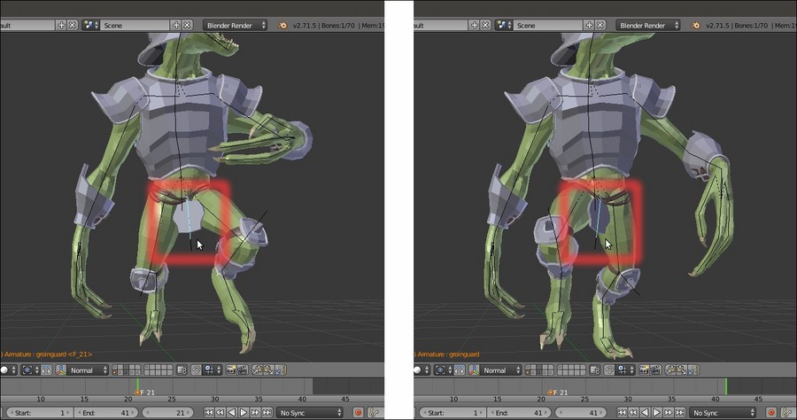
The groinguard bone (and plate) automatically rotating during the walk cycle
The armor_ctrl bone is the bone controlling the armor's Breastplate; it's the child of the chest bone, so it inherits the rotation of the chest, but has four Transformation constraints.
By using as an input the rotation angle of the rotarmor.L and rotarmor.R bones (which are children themselves of the arm.L and arm.R bones), the constraints give to the Armor chest plate a slight rotation on the vertical axis and a lateral swinging, driven by the oscillations of the Gidiosaurus arms, and simulating of the character's shoulders colliding with the armor plate during the walk.
Also, the spaulders are, in turn, partially rotated by bones with the Copy Rotation constraints targeted to the arms, but with quite a low influence.
Although better appreciated in motion, the following screenshot will show you the effects as the arms rotate backward:

The rotation and swinging of the armor chest plate according to the arms' movements
Getting ready
Start from the previously saved Gidiosaurus_rig_from_scratch_01.blend file:
- Enable the 13th scene layer to show the Armor object.
- Select it and go to the Object Modifiers window under the main Properties panel. Expand the Subdivision Surface modifier tab and click on the Display modifier in viewport button, the one with the eye icon, to disable it.
- Go to the Outliner and click on the arrow icon to the side of the Armor item to make it unselectable.
- Click on the arrow icon to the side of the Gidiosaurus_lowres item to make it unselectable as well.
- Save the file as
Gidiosaurus_rig_from_scratch_02.blend.
Let's start by adding bones dedicated to the Armor:
- Go into Edit Mode and select the forearm.L bone; use Shift + D to duplicate it and rename it vanbrace.L. Press M and in the Change Bone Layers pop-up, click on the 2nd button to move the duplicated bone to that bone layer.
- Do the same for the forearm.R bone (vanbrace.R) and for the calf.L (greave.L) and calf.R bones (greave.R).
- Now, go to the Object Data window and click on the 2nd button under the Layers item in the Skeleton subpanel, in order to show only the four duplicated bones in the 3D viewport; press Tab to get out of Edit Mode.
- Select the vanbrace.L bone and go to the Bone window under the Deform subpanel; under the Curved Bones item, set back the Segments and Ease In and Ease Out values to default, that is, 1, 1.000 and 1.000.
- Go back into Edit Mode and click on the Connected item under the Relations subpanel.
- Get out of Edit Mode and go to the Bone Constraints window under the main Properties panel (not to be confused with the Object Constraints window); click on the Add Bone Constraint button and select a Copy Rotation constraint from the pop-up menu (the bone turns light green, in order to show that it has a constraint assigned now).
- In the Target field, select Armature; in the Bone field, select the forearm.L item; in the Space fields, select Pose Space for both.
Alternatively, for steps 6 and 7, select the forearm.L bone and then use Shift to select the vanbrace.L bone. Hence, press Shift + Ctrl + C to call the Add Constraint (with Targets) pop-up menu and select the Copy Rotation item. This will automatically add the Copy Rotation constraint to the vanbrace.L bone, with the first select bone (forearm.L) as a target; the other setting must be enabled and/or tweaked in the constraint subpanel instead.
- Click again on the Add Bone Constraint button and this time, select an Inverse Kinematics constraint (the bone turns yellow, in order to show that an IK solver has been assigned). In the Target field, select the Armature item, in the Bone field, select the hand.L bone, and set the Chain Length to 1; deselect Stretch and select Rotation, lowering the weight to the minimum (that is 0.010):
The constraints assigned to the forearm.L b-bone
- Repeat the steps from 4 to 8 for the other three duplicated bones (obviously, setting the appropriate bones as targets for each pair of constraints; the target bone for the IK constraint assigned to the greave bones is the respective foot bone).
The rig can now drive the vambraces and greaves; let's see the knee guards and Groinguard.
- First, switch the Armature visualization back to Octahedral, then go into Edit Mode, select the hips bone and use Shift + D to duplicate it; in the Side view, rotate the duplicate 170 degrees, then move it on the Groinguard part of the armor, in order to have the Head of the bone placed to the joint of the plate with the ties; select the Tail of the groinguard bone and scale it smaller to fit the part.
- To position the bone more precisely, go to the Transform subpanel under the Properties 3D view sidepanel and set the following values for the Head (of the bone): X = 0.001, Y = 0.020, and Z = 1.147; for the Tail set the following values: X = 0.001, Y = 0.022, and Z = 0.873.
- Go to the Item subpanel and rename the bone from hips.001 to groinguard:
The groinguard bone
- Go to the Bone window in the main Properties panel, and under the Relations subpanel, click on the Parent empty slot to select the hips item.
- Now, select the joint of the leg.L bone with the calf.L bone and press Shift + S | Cursor to Selected; press Shift + A to add a new bone and rescale it smaller.
- Select the whole new bone and use Shift to select the calf.L bone. Then, go in the 3D view toolbar and click on the Armature item; go to Transform | Align Bones (or else, press the Ctrl + Alt + A keys) to align the new bone as the calf.L one.
- Enable the widget (Ctrl + spacebar), set the Transform Orientation to Normal, and the rotation pivot on the 3D Cursor. Then, rotate the new bone 110 degrees on the normal x axis (the red wheel of the widget, or else R | X | X | 110 | Enter):
Aligning the new bone
- Go into Object Mode and press Shift + S | Cursor to Selected to place the 3D Cursor at the median pivot point of the Armature; go back into Edit Mode, press Shift + D to duplicate the new bone, then Ctrl + M | X to mirror it on the other side.
- Rename the new bones as kneeguard.L and kneeguard.R; enable the axis visibility and recalculate the roll by the Ctrl + N | Active Bone tool:
Recalculating the roll angle of the kneeguard bones
- Parent the kneeguard.L bone to the leg.L bone and the kneeguard.R bone to the leg.R one (not connected).
- Select the groinguard bone and use Shift + D to duplicate it, and then scale the duplicated bone a little bit bigger and rename it as groinguard_ctrl; uncheck the box of the Deform subpanel under the Bone window:
Creating a control bone for the groinguard bone
- Select the groinguard bone, go to the Relations subpanel, and click in the Parent field to select the groinguard_ctrl bone.
- Get out of Edit Mode and in Pose Mode, select the groinguard_ctrl bone.
- Go to the Bone Constraints window under the main Properties panel; click on the Add Bone Constraint button and select a Locked Track constraint from the pop-up menu.
- In the Target field, select the Armature item; in the Bone field, select the kneeguard.L item. Set the Head/Tail value to 0.500: To (Axis that points to the target object) = -X and Lock (Axis that points upward) = Y. In the Constraint Name field, rename it as Locked Track.L.
- Add a new Locked Track constraint and repeat everything as in the previous one, except in the Bone field, select the kneeguard.R item; rename it as Locked Track.R.
- Add a Damped Track constraint: Target = Armature, Bone = kneeguard.L, Head/Tail = 0.728, To = Y, and Influence = 0.263. Rename it as Damped Track.L.
- Add a new Damped Track constraint and repeat everything as in the previous one, except again in the Bone field, select the kneeguard.R item; rename it as Damped Track.R.
- Just to be sure, save the file!
- Go back into Edit Mode and in the Side view, select the chest bone and use Shift + D to duplicate it. Press W to call the Specials pop-up menu and select the Switch_Direction item, or else press Alt + F directly:
The Specials pop-up menu for the bones
- Go to the Bone window and click on the Parent slot under the Relations subpanel to select the chest item (not connected); then, go to the Deform subpanel and set the Segments under Curved Bones to 1. Rename the new bone as armor_ctrl.
- Press Ctrl + R to roll the armor_ctrl bone, in order to be sure that its local x axis is pointing towards the front of the model; this is important to make the Transformation constraints, which we'll add later, work properly:
The armor control bone
- Go in the Front view. Note that the X-Axis Mirror item in the Armature Options panel under the Tool Shelf is still enabled; select the Tail of the shoulder.L bone and extrude a new bone going towards the external edge of the armor spaulder. Then, select the extruded bone, press Alt + P | Clear Parent, and move its Head to be positioned above the joint of the spaulder with the chest plate.
Creating the bone for the spaulder
- Rename the extruded bone and the corresponding mirrored one as spaulder.L and spaulder.R; parent them to the armor_ctrl bone (enable the Keep Offset item).
- Use Shift to select the spaulder.L and arm.L bones and press Ctrl + N | Active Bone; do the same with the spaulder.R and arm.R bones.
- Now, put the 3D Cursor at the spaulder.L bone's Head location, and then set the Pivot Point to the 3D Cursor in the 3D window toolbar. Use Shift + D to duplicate the spaulder.L bone and rotate the duplicate 70 degrees (in the Front view, R | 70 | Enter).
- Place the 3D Cursor at the shoulder.L bone's Tail location, select the duplicated bone, and press Shift + S | Selected to Cursor. Rename the duplicated bone and the mirrored one as rotarmor.L and rotarmor.R. Go to the Relations subpanel and set the rotarmor.L bone as the child of the arm.L bone and the rotarmor.R bone as the child of the arm.R bone. Disable the Deform item for both of them:
Using the 3D Cursor and the Snap menu to exactly place the bones
- Go into Pose Mode. Select the spaulder.L bone and in the Bone Constraints window, assign a Copy Rotation constraint: Target = Armature, Bone = arm.L, Space = Pose Space to Pose Space, and Influence = 0.200.
- Select the spaulder.R bone and repeat with the Bone = arm.R target.
- Now, select the armor_ctrl bone and assign a Transformation constraint. Set Target = Armature, Bone = rotarmor.L, Source = Rot, and Z Max = 20°; Source To Destination Mapping = switch X with Z; Destination = Rot, X Max = 4°, and Space = Pose Space to Pose Space. Rename the constraint as Transformation_rot.L and collapse the panel.
- Assign a second Transformation constraint; set everything as in the previous one, except for the target Bone = rotarmor.R, Source = Rot, Z Min = -20°, and Destination X Min = -4°. Rename the constraint as Transformation_rot.R and collapse it.
- Assign a third Transformation constraint; set everything as in the first one, except do not switch X with Z, set Destination = Loc and Z Max = 0.050. Rename the constraint as Transformation_move.L and collapse it.
- Assign a fourth Transformation constraint; set everything as in the second one, except do not switch X with Z; set Destination = Loc and Z Min = 0.050. Rename the constraint as Transformation_move.R and collapse it.
- Save the file.
We couldn't directly use the forearm and calf bones to rig the vanbraces and greaves parts because being subdivided B-bones, they would curve these armor parts along the length as they actually do by deforming organic parts as the forearms and shins, and this would look awkward, as you can see in the following screenshot:
B-bones erroneously deforming stiff objects
Instead, we just duplicated the bones, restored Segments and Ease In and Ease Out to default values, and assigned 2 bone constraints (note that, as already mentioned, the bones have a Bone Constraints panel of their own, which is different from the Object Constraints one).
The Copy Rotation constraint, as the name itself explains, copies the rotation in space of the target B-bone; the position inside the chain is granted because the duplicated bones, although not connected, are children of the same bones as the original ones.
The Inverse Kinematics constraint—in this case, is used simply to track the local y rotation of the hand bone in order to rotate correctly on its y axis— is necessary because the Copy Rotation constraint doesn't seem to read the local y rotation of a subdivided B-bone (besides the technical details, it makes sense because that's actually not a rotation in space):
The correct rotation of the stiff armor parts
The constraints assigned to the groinguard_ctrl bone are a cheap, but quite an effective, way to fake a rigid body simulation for the plate that—in actions, for example, a walk cycle—should interact by colliding with the Gidiosaurus thighs. The Locked Track constraints, targeted to the leg bones, automatically rotate the plate according to the thighs movements, and the Dumped Track constraints, targeted to the leg bones as well but with a low influence, add a swinging movement.
The groinguard bone, actually the one affecting the armor plate, is the child of the groinguard_ctrl bone, and so it inherits the constraint's movements but can be used to refine, tweak, or modify the final animation of the plate by hands:
The groinguard bone (and plate) automatically rotating during the walk cycle
The armor_ctrl bone is the bone controlling the armor's Breastplate; it's the child of the chest bone, so it inherits the rotation of the chest, but has four Transformation constraints.
By using as an input the rotation angle of the rotarmor.L and rotarmor.R bones (which are children themselves of the arm.L and arm.R bones), the constraints give to the Armor chest plate a slight rotation on the vertical axis and a lateral swinging, driven by the oscillations of the Gidiosaurus arms, and simulating of the character's shoulders colliding with the armor plate during the walk.
Also, the spaulders are, in turn, partially rotated by bones with the Copy Rotation constraints targeted to the arms, but with quite a low influence.
Although better appreciated in motion, the following screenshot will show you the effects as the arms rotate backward:
The rotation and swinging of the armor chest plate according to the arms' movements
How to do it…
Let's start by adding bones dedicated to the Armor:
- Go into Edit Mode and select the forearm.L bone; use Shift + D to duplicate it and rename it vanbrace.L. Press M and in the Change Bone Layers pop-up, click on the 2nd button to move the duplicated bone to that bone layer.
- Do the same for the forearm.R bone (vanbrace.R) and for the calf.L (greave.L) and calf.R bones (greave.R).
- Now, go to the Object Data window and click on the 2nd button under the Layers item in the Skeleton subpanel, in order to show only the four duplicated bones in the 3D viewport; press Tab to get out of Edit Mode.
- Select the vanbrace.L bone and go to the Bone window under the Deform subpanel; under the Curved Bones item, set back the Segments and Ease In and Ease Out values to default, that is, 1, 1.000 and 1.000.
- Go back into Edit Mode and click on the Connected item under the Relations subpanel.
- Get out of Edit Mode and go to the Bone Constraints window under the main Properties panel (not to be confused with the Object Constraints window); click on the Add Bone Constraint button and select a Copy Rotation constraint from the pop-up menu (the bone turns light green, in order to show that it has a constraint assigned now).
- In the Target field, select Armature; in the Bone field, select the forearm.L item; in the Space fields, select Pose Space for both.
Alternatively, for steps 6 and 7, select the forearm.L bone and then use Shift to select the vanbrace.L bone. Hence, press Shift + Ctrl + C to call the Add Constraint (with Targets) pop-up menu and select the Copy Rotation item. This will automatically add the Copy Rotation constraint to the vanbrace.L bone, with the first select bone (forearm.L) as a target; the other setting must be enabled and/or tweaked in the constraint subpanel instead.
- Click again on the Add Bone Constraint button and this time, select an Inverse Kinematics constraint (the bone turns yellow, in order to show that an IK solver has been assigned). In the Target field, select the Armature item, in the Bone field, select the hand.L bone, and set the Chain Length to 1; deselect Stretch and select Rotation, lowering the weight to the minimum (that is 0.010):
The constraints assigned to the forearm.L b-bone
- Repeat the steps from 4 to 8 for the other three duplicated bones (obviously, setting the appropriate bones as targets for each pair of constraints; the target bone for the IK constraint assigned to the greave bones is the respective foot bone).
The rig can now drive the vambraces and greaves; let's see the knee guards and Groinguard.
- First, switch the Armature visualization back to Octahedral, then go into Edit Mode, select the hips bone and use Shift + D to duplicate it; in the Side view, rotate the duplicate 170 degrees, then move it on the Groinguard part of the armor, in order to have the Head of the bone placed to the joint of the plate with the ties; select the Tail of the groinguard bone and scale it smaller to fit the part.
- To position the bone more precisely, go to the Transform subpanel under the Properties 3D view sidepanel and set the following values for the Head (of the bone): X = 0.001, Y = 0.020, and Z = 1.147; for the Tail set the following values: X = 0.001, Y = 0.022, and Z = 0.873.
- Go to the Item subpanel and rename the bone from hips.001 to groinguard:
The groinguard bone
- Go to the Bone window in the main Properties panel, and under the Relations subpanel, click on the Parent empty slot to select the hips item.
- Now, select the joint of the leg.L bone with the calf.L bone and press Shift + S | Cursor to Selected; press Shift + A to add a new bone and rescale it smaller.
- Select the whole new bone and use Shift to select the calf.L bone. Then, go in the 3D view toolbar and click on the Armature item; go to Transform | Align Bones (or else, press the Ctrl + Alt + A keys) to align the new bone as the calf.L one.
- Enable the widget (Ctrl + spacebar), set the Transform Orientation to Normal, and the rotation pivot on the 3D Cursor. Then, rotate the new bone 110 degrees on the normal x axis (the red wheel of the widget, or else R | X | X | 110 | Enter):
Aligning the new bone
- Go into Object Mode and press Shift + S | Cursor to Selected to place the 3D Cursor at the median pivot point of the Armature; go back into Edit Mode, press Shift + D to duplicate the new bone, then Ctrl + M | X to mirror it on the other side.
- Rename the new bones as kneeguard.L and kneeguard.R; enable the axis visibility and recalculate the roll by the Ctrl + N | Active Bone tool:
Recalculating the roll angle of the kneeguard bones
- Parent the kneeguard.L bone to the leg.L bone and the kneeguard.R bone to the leg.R one (not connected).
- Select the groinguard bone and use Shift + D to duplicate it, and then scale the duplicated bone a little bit bigger and rename it as groinguard_ctrl; uncheck the box of the Deform subpanel under the Bone window:
Creating a control bone for the groinguard bone
- Select the groinguard bone, go to the Relations subpanel, and click in the Parent field to select the groinguard_ctrl bone.
- Get out of Edit Mode and in Pose Mode, select the groinguard_ctrl bone.
- Go to the Bone Constraints window under the main Properties panel; click on the Add Bone Constraint button and select a Locked Track constraint from the pop-up menu.
- In the Target field, select the Armature item; in the Bone field, select the kneeguard.L item. Set the Head/Tail value to 0.500: To (Axis that points to the target object) = -X and Lock (Axis that points upward) = Y. In the Constraint Name field, rename it as Locked Track.L.
- Add a new Locked Track constraint and repeat everything as in the previous one, except in the Bone field, select the kneeguard.R item; rename it as Locked Track.R.
- Add a Damped Track constraint: Target = Armature, Bone = kneeguard.L, Head/Tail = 0.728, To = Y, and Influence = 0.263. Rename it as Damped Track.L.
- Add a new Damped Track constraint and repeat everything as in the previous one, except again in the Bone field, select the kneeguard.R item; rename it as Damped Track.R.
- Just to be sure, save the file!
- Go back into Edit Mode and in the Side view, select the chest bone and use Shift + D to duplicate it. Press W to call the Specials pop-up menu and select the Switch_Direction item, or else press Alt + F directly:
The Specials pop-up menu for the bones
- Go to the Bone window and click on the Parent slot under the Relations subpanel to select the chest item (not connected); then, go to the Deform subpanel and set the Segments under Curved Bones to 1. Rename the new bone as armor_ctrl.
- Press Ctrl + R to roll the armor_ctrl bone, in order to be sure that its local x axis is pointing towards the front of the model; this is important to make the Transformation constraints, which we'll add later, work properly:
The armor control bone
- Go in the Front view. Note that the X-Axis Mirror item in the Armature Options panel under the Tool Shelf is still enabled; select the Tail of the shoulder.L bone and extrude a new bone going towards the external edge of the armor spaulder. Then, select the extruded bone, press Alt + P | Clear Parent, and move its Head to be positioned above the joint of the spaulder with the chest plate.
Creating the bone for the spaulder
- Rename the extruded bone and the corresponding mirrored one as spaulder.L and spaulder.R; parent them to the armor_ctrl bone (enable the Keep Offset item).
- Use Shift to select the spaulder.L and arm.L bones and press Ctrl + N | Active Bone; do the same with the spaulder.R and arm.R bones.
- Now, put the 3D Cursor at the spaulder.L bone's Head location, and then set the Pivot Point to the 3D Cursor in the 3D window toolbar. Use Shift + D to duplicate the spaulder.L bone and rotate the duplicate 70 degrees (in the Front view, R | 70 | Enter).
- Place the 3D Cursor at the shoulder.L bone's Tail location, select the duplicated bone, and press Shift + S | Selected to Cursor. Rename the duplicated bone and the mirrored one as rotarmor.L and rotarmor.R. Go to the Relations subpanel and set the rotarmor.L bone as the child of the arm.L bone and the rotarmor.R bone as the child of the arm.R bone. Disable the Deform item for both of them:
Using the 3D Cursor and the Snap menu to exactly place the bones
- Go into Pose Mode. Select the spaulder.L bone and in the Bone Constraints window, assign a Copy Rotation constraint: Target = Armature, Bone = arm.L, Space = Pose Space to Pose Space, and Influence = 0.200.
- Select the spaulder.R bone and repeat with the Bone = arm.R target.
- Now, select the armor_ctrl bone and assign a Transformation constraint. Set Target = Armature, Bone = rotarmor.L, Source = Rot, and Z Max = 20°; Source To Destination Mapping = switch X with Z; Destination = Rot, X Max = 4°, and Space = Pose Space to Pose Space. Rename the constraint as Transformation_rot.L and collapse the panel.
- Assign a second Transformation constraint; set everything as in the previous one, except for the target Bone = rotarmor.R, Source = Rot, Z Min = -20°, and Destination X Min = -4°. Rename the constraint as Transformation_rot.R and collapse it.
- Assign a third Transformation constraint; set everything as in the first one, except do not switch X with Z, set Destination = Loc and Z Max = 0.050. Rename the constraint as Transformation_move.L and collapse it.
- Assign a fourth Transformation constraint; set everything as in the second one, except do not switch X with Z; set Destination = Loc and Z Min = 0.050. Rename the constraint as Transformation_move.R and collapse it.
- Save the file.
We couldn't directly use the forearm and calf bones to rig the vanbraces and greaves parts because being subdivided B-bones, they would curve these armor parts along the length as they actually do by deforming organic parts as the forearms and shins, and this would look awkward, as you can see in the following screenshot:
B-bones erroneously deforming stiff objects
Instead, we just duplicated the bones, restored Segments and Ease In and Ease Out to default values, and assigned 2 bone constraints (note that, as already mentioned, the bones have a Bone Constraints panel of their own, which is different from the Object Constraints one).
The Copy Rotation constraint, as the name itself explains, copies the rotation in space of the target B-bone; the position inside the chain is granted because the duplicated bones, although not connected, are children of the same bones as the original ones.
The Inverse Kinematics constraint—in this case, is used simply to track the local y rotation of the hand bone in order to rotate correctly on its y axis— is necessary because the Copy Rotation constraint doesn't seem to read the local y rotation of a subdivided B-bone (besides the technical details, it makes sense because that's actually not a rotation in space):
The correct rotation of the stiff armor parts
The constraints assigned to the groinguard_ctrl bone are a cheap, but quite an effective, way to fake a rigid body simulation for the plate that—in actions, for example, a walk cycle—should interact by colliding with the Gidiosaurus thighs. The Locked Track constraints, targeted to the leg bones, automatically rotate the plate according to the thighs movements, and the Dumped Track constraints, targeted to the leg bones as well but with a low influence, add a swinging movement.
The groinguard bone, actually the one affecting the armor plate, is the child of the groinguard_ctrl bone, and so it inherits the constraint's movements but can be used to refine, tweak, or modify the final animation of the plate by hands:
The groinguard bone (and plate) automatically rotating during the walk cycle
The armor_ctrl bone is the bone controlling the armor's Breastplate; it's the child of the chest bone, so it inherits the rotation of the chest, but has four Transformation constraints.
By using as an input the rotation angle of the rotarmor.L and rotarmor.R bones (which are children themselves of the arm.L and arm.R bones), the constraints give to the Armor chest plate a slight rotation on the vertical axis and a lateral swinging, driven by the oscillations of the Gidiosaurus arms, and simulating of the character's shoulders colliding with the armor plate during the walk.
Also, the spaulders are, in turn, partially rotated by bones with the Copy Rotation constraints targeted to the arms, but with quite a low influence.
Although better appreciated in motion, the following screenshot will show you the effects as the arms rotate backward:
The rotation and swinging of the armor chest plate according to the arms' movements
How it works…
We couldn't directly use the forearm and calf bones to rig the vanbraces and greaves parts because being subdivided B-bones, they would curve these armor parts along the length as they actually do by deforming organic parts as the forearms and shins, and this would look awkward, as you can see in the following screenshot:
B-bones erroneously deforming stiff objects
Instead, we just duplicated the bones, restored Segments and Ease In and Ease Out to default values, and assigned 2 bone constraints (note that, as already mentioned, the bones have a Bone Constraints panel of their own, which is different from the Object Constraints one).
The Copy Rotation constraint, as the name itself explains, copies the rotation in space of the target B-bone; the position inside the chain is granted because the duplicated bones, although not connected, are children of the same bones as the original ones.
The Inverse Kinematics constraint—in this case, is used simply to track the local y rotation of the hand bone in order to rotate correctly on its y axis— is necessary because the Copy Rotation constraint doesn't seem to read the local y rotation of a subdivided B-bone (besides the technical details, it makes sense because that's actually not a rotation in space):
The correct rotation of the stiff armor parts
The constraints assigned to the groinguard_ctrl bone are a cheap, but quite an effective, way to fake a rigid body simulation for the plate that—in actions, for example, a walk cycle—should interact by colliding with the Gidiosaurus thighs. The Locked Track constraints, targeted to the leg bones, automatically rotate the plate according to the thighs movements, and the Dumped Track constraints, targeted to the leg bones as well but with a low influence, add a swinging movement.
The groinguard bone, actually the one affecting the armor plate, is the child of the groinguard_ctrl bone, and so it inherits the constraint's movements but can be used to refine, tweak, or modify the final animation of the plate by hands:
The groinguard bone (and plate) automatically rotating during the walk cycle
The armor_ctrl bone is the bone controlling the armor's Breastplate; it's the child of the chest bone, so it inherits the rotation of the chest, but has four Transformation constraints.
By using as an input the rotation angle of the rotarmor.L and rotarmor.R bones (which are children themselves of the arm.L and arm.R bones), the constraints give to the Armor chest plate a slight rotation on the vertical axis and a lateral swinging, driven by the oscillations of the Gidiosaurus arms, and simulating of the character's shoulders colliding with the armor plate during the walk.
Also, the spaulders are, in turn, partially rotated by bones with the Copy Rotation constraints targeted to the arms, but with quite a low influence.
Although better appreciated in motion, the following screenshot will show you the effects as the arms rotate backward:
The rotation and swinging of the armor chest plate according to the arms' movements
In the previous long and quite complex recipe, we hand-built the deforming elements of an average basic rig for the Gidiosaurus character; actually, in Blender, there are other tools to build rigs, particularly meant to facilitate the task, and we'll see them in this recipe and in the following ones.
Now, we are going to take a look at the Human Meta-Rig tool.
To be able to use the Human Meta-Rig tool, we must first enable the proper add-on:
- Start Blender and press Ctrl + Alt + U to call the User Preferences panel. Go to the Add-ons tab and under Categories on the left-hand side, click on the Rigging item. Go to the right-hand side of the panel and check the box to the side of the Rigging: Rigify add-on to enable it.
- Click on the Save User Settings button at the bottom-left of the panel and then close it. Because we are starting a rig from scratch again, load the
Gidiosaurus_unwrap_final.blendfile. - Disable the Textured Solid and Backface Culling items in the 3D view Properties panel, join the 3D window with the UV/Image Editor window, and click on the 11th scene layer to have only the Gidiosaurus mesh visible.
- Go to the Object window and under the Display subpanel, enable the Wire item; this will be useful in the process to have an idea of the mesh topology when in Object Mode and in Solid viewport shading mode. However, for the moment, press Z to go in the Wireframe viewport shading mode.
- Press 1 on the numpad to go in the Front view and 5 on the numpad again to switch to the Ortho view.
- Save the file as
Gidiosaurus_meta_rigging.blend.
Let's go with the metarig itself:
- Ensure that the 3D Cursor is at the origin pivot point of the Gidiosaurus mesh. Put the mouse cursor in the 3D viewport, press Shift + A, and in the pop-up menu, select Armature | Human (Meta-Rig); a biped Armature, automatically named metarig in the Outliner, appears at the 3D Cursor location:

The Human (Meta-Rig) menu and the rig
- Press the Tab key to enter Edit Mode and go to the Options tab that appeared under the Tool Shelf on the left-hand side of the screen; check the box to enable the X-Axis Mirror tool under the Armature Options item.
- First, press the period (.) key to set the pivot point around the 3D Cursor and scale the whole armature bigger while still in Edit Mode, and then start to edit locations and proportions of the bones of the metarig to fit inside the Gidiosaurus shape:

Tweaking the proportions of the bones of the metarig
- Select the single joints to move them on the right location according to the mesh topology; to do this in a more exact way, just use the snap technique explained in steps 25 and 26 of the How to do it… section of the Building the character's Armature from scratch recipe. Because of the X-Axis Mirror tool we enabled, it's enough to operate only on one side of the metarig:

Further tweaking of the bones in Edit Mode
- Delete the bones that you don't need, for example the extra fingers (consider that the Gidiosaurus has only three fingers in each hand), use Shift + D to duplicate the bones to be added, for example for the toes, and add new bones where missing, for example for the jaw, and then parent them. In short, just edit the rig as usual. Again, it should be enough to do all these operations just on one side of the rig:

The completed skeleton rig
- Save the file.
We can also add premade rigging sets, for example a whole new leg, spine, or arm, by going, with the metarig still in Edit Mode, to the Rigify Buttons subpanel under the Armature window in the main Properties panel. Select the desired item to be added to the rig and click on the Add sample button; the new part gets added to the rig's pivot point location and must be moved to the right place and tweaked, rotated, and scaled as needed. Also, the new bones must be named with the correct .R or .L suffix and the top chain bone must be parented to the bottom metarig bone; for example, in the case of a biped.leg part addition, the thigh bone must be parented (Ctrl + P | Keep Offset) to the hips bone:

Adding premade rig to the skeleton
The Human metarig is actually only the first part of a more complex and complete auto-rigging system named Rigify, and this we'll see in the next recipe. However, even used by itself, it gives us a readymade humanoid skeleton to be simply tweaked to fit the character's shape: a good shortcut to quickly build the Armature rig considering that, at least in its basic form, all the bones are already properly connected and named with the .L and .R suffices.
Getting ready
To be able to use the Human Meta-Rig tool, we must first enable the proper add-on:
- Start Blender and press Ctrl + Alt + U to call the User Preferences panel. Go to the Add-ons tab and under Categories on the left-hand side, click on the Rigging item. Go to the right-hand side of the panel and check the box to the side of the Rigging: Rigify add-on to enable it.
- Click on the Save User Settings button at the bottom-left of the panel and then close it. Because we are starting a rig from scratch again, load the
Gidiosaurus_unwrap_final.blendfile. - Disable the Textured Solid and Backface Culling items in the 3D view Properties panel, join the 3D window with the UV/Image Editor window, and click on the 11th scene layer to have only the Gidiosaurus mesh visible.
- Go to the Object window and under the Display subpanel, enable the Wire item; this will be useful in the process to have an idea of the mesh topology when in Object Mode and in Solid viewport shading mode. However, for the moment, press Z to go in the Wireframe viewport shading mode.
- Press 1 on the numpad to go in the Front view and 5 on the numpad again to switch to the Ortho view.
- Save the file as
Gidiosaurus_meta_rigging.blend.
Let's go with the metarig itself:
- Ensure that the 3D Cursor is at the origin pivot point of the Gidiosaurus mesh. Put the mouse cursor in the 3D viewport, press Shift + A, and in the pop-up menu, select Armature | Human (Meta-Rig); a biped Armature, automatically named metarig in the Outliner, appears at the 3D Cursor location:
The Human (Meta-Rig) menu and the rig
- Press the Tab key to enter Edit Mode and go to the Options tab that appeared under the Tool Shelf on the left-hand side of the screen; check the box to enable the X-Axis Mirror tool under the Armature Options item.
- First, press the period (.) key to set the pivot point around the 3D Cursor and scale the whole armature bigger while still in Edit Mode, and then start to edit locations and proportions of the bones of the metarig to fit inside the Gidiosaurus shape:
Tweaking the proportions of the bones of the metarig
- Select the single joints to move them on the right location according to the mesh topology; to do this in a more exact way, just use the snap technique explained in steps 25 and 26 of the How to do it… section of the Building the character's Armature from scratch recipe. Because of the X-Axis Mirror tool we enabled, it's enough to operate only on one side of the metarig:
Further tweaking of the bones in Edit Mode
- Delete the bones that you don't need, for example the extra fingers (consider that the Gidiosaurus has only three fingers in each hand), use Shift + D to duplicate the bones to be added, for example for the toes, and add new bones where missing, for example for the jaw, and then parent them. In short, just edit the rig as usual. Again, it should be enough to do all these operations just on one side of the rig:
The completed skeleton rig
- Save the file.
We can also add premade rigging sets, for example a whole new leg, spine, or arm, by going, with the metarig still in Edit Mode, to the Rigify Buttons subpanel under the Armature window in the main Properties panel. Select the desired item to be added to the rig and click on the Add sample button; the new part gets added to the rig's pivot point location and must be moved to the right place and tweaked, rotated, and scaled as needed. Also, the new bones must be named with the correct .R or .L suffix and the top chain bone must be parented to the bottom metarig bone; for example, in the case of a biped.leg part addition, the thigh bone must be parented (Ctrl + P | Keep Offset) to the hips bone:
Adding premade rig to the skeleton
The Human metarig is actually only the first part of a more complex and complete auto-rigging system named Rigify, and this we'll see in the next recipe. However, even used by itself, it gives us a readymade humanoid skeleton to be simply tweaked to fit the character's shape: a good shortcut to quickly build the Armature rig considering that, at least in its basic form, all the bones are already properly connected and named with the .L and .R suffices.
How to do it…
Let's go with the metarig itself:
- Ensure that the 3D Cursor is at the origin pivot point of the Gidiosaurus mesh. Put the mouse cursor in the 3D viewport, press Shift + A, and in the pop-up menu, select Armature | Human (Meta-Rig); a biped Armature, automatically named metarig in the Outliner, appears at the 3D Cursor location:
The Human (Meta-Rig) menu and the rig
- Press the Tab key to enter Edit Mode and go to the Options tab that appeared under the Tool Shelf on the left-hand side of the screen; check the box to enable the X-Axis Mirror tool under the Armature Options item.
- First, press the period (.) key to set the pivot point around the 3D Cursor and scale the whole armature bigger while still in Edit Mode, and then start to edit locations and proportions of the bones of the metarig to fit inside the Gidiosaurus shape:
Tweaking the proportions of the bones of the metarig
- Select the single joints to move them on the right location according to the mesh topology; to do this in a more exact way, just use the snap technique explained in steps 25 and 26 of the How to do it… section of the Building the character's Armature from scratch recipe. Because of the X-Axis Mirror tool we enabled, it's enough to operate only on one side of the metarig:
Further tweaking of the bones in Edit Mode
- Delete the bones that you don't need, for example the extra fingers (consider that the Gidiosaurus has only three fingers in each hand), use Shift + D to duplicate the bones to be added, for example for the toes, and add new bones where missing, for example for the jaw, and then parent them. In short, just edit the rig as usual. Again, it should be enough to do all these operations just on one side of the rig:
The completed skeleton rig
- Save the file.
We can also add premade rigging sets, for example a whole new leg, spine, or arm, by going, with the metarig still in Edit Mode, to the Rigify Buttons subpanel under the Armature window in the main Properties panel. Select the desired item to be added to the rig and click on the Add sample button; the new part gets added to the rig's pivot point location and must be moved to the right place and tweaked, rotated, and scaled as needed. Also, the new bones must be named with the correct .R or .L suffix and the top chain bone must be parented to the bottom metarig bone; for example, in the case of a biped.leg part addition, the thigh bone must be parented (Ctrl + P | Keep Offset) to the hips bone:
Adding premade rig to the skeleton
The Human metarig is actually only the first part of a more complex and complete auto-rigging system named Rigify, and this we'll see in the next recipe. However, even used by itself, it gives us a readymade humanoid skeleton to be simply tweaked to fit the character's shape: a good shortcut to quickly build the Armature rig considering that, at least in its basic form, all the bones are already properly connected and named with the .L and .R suffices.
How it works…
The Human metarig is actually only the first part of a more complex and complete auto-rigging system named Rigify, and this we'll see in the next recipe. However, even used by itself, it gives us a readymade humanoid skeleton to be simply tweaked to fit the character's shape: a good shortcut to quickly build the Armature rig considering that, at least in its basic form, all the bones are already properly connected and named with the .L and .R suffices.
Whether we built the Gidiosaurus deforming rig part by hands from scratch or by the Human Meta-rig, we must now add the necessary constraints and controls to allow the animators to easily manipulate the character.
Note
Note that once the mesh is skinned, the rig, as it is at this point, can actually already work by directly selecting the interested bones and rotating them in Forward Kinematics; however, to simplify the animator's work (and complicate our life a little bit more), it's good practice to add the Inverse Kinematic constraints and the control bones.
Let's start by opening the Gidiosaurus_rig_from_scratch_02.blend file; as usual, enter Edit Mode to ensure that the X-Axis Mirror item in the Armature Options subpanel under the Tool Shelf is enabled.
We now need to create the control bones; we can do it by extruding from the bones they will drive:
- Press the 3 key on the numpad to go in the Side view and, if not already, select the Armature; if necessary, in the Display subpanel, change the visualization of the bones from B-Bone to Octahedral.
- While still in Edit Mode, use Shift to select the joints of the hand with the forearm and the calf with the foot (it's enough only on one side) and extrude them going backwards (0.400 along global y axis).
- Rename the new extruded bones as ctrl_hand.L, ctrl_hand.R, ctrl_foot.L, and ctrl_foot.R respectively. Deselect the Deform item and unparent them all.
- Select the Head of the hips bone and repeat: rename the extruded bone as MAIN.
- Select the hips bone and in the Relations subpanel, parent it as a child of the MAIN bone:

Extruding the control bones part 1
- Select the elbow joint (between the forearm and arm) and extrude a new bone backwards; rename the extruded bone and the mirrored one as elbow.L and elbow.R. Disable the Deform item and parent them (Keep Offset) to the MAIN bone. Move them backwards by 0.500 along the global y axis.
- Select the knee joint (between the thigh and calf) and extrude forward; rename the new bones as knee.L and knee.R. Disable the Deform item and parent them (Keep Offset) to the MAIN bone as well. Move them forward by -0.500 along the global y axis;

Extruding the control bones part 2
- Go into Pose Mode and select the forearm.L bone; go to the Bone Constraints window and assign an Inverse Kinematics constraint. Set Target = Armature, Bone = ctrl_hand.L, Pole Target = Armature, Bone = elbow.L, Pole Angle = -90°, and Chain Length = 2, and deselect Stretch. Repeat the process for the forearm.R bone:

Assigning the IK constraint to the forearm.L bone
- Do the same for the calf.L and calf.R bones, using the ctrl_foot.L and ctrl_foot.R bones as targets and the knee.L and knee.R bones as poles, but set the Pole Angle to 90° for both.
- Now, go back into Edit Mode, select the hand and foot bones, and use Shift + D to duplicate them. Click on the Pivot Point button on the 3D view toolbar, select the Individual Origins item, and then scale the duplicated bones smaller to 0.600:

Scaling the bones smaller on their individual origin
- Deselect the Deform item for all of them, and then rename them as: handrot.L, handrot.R, footrot.L, and footrot.R.
- In the Relations subpanel (or by the Ctrl + P | Keep Offset shortcut), parent handrot.L to ctrl_hand.L, handrot.R to ctrl_hand.R, footrot.L to ctrl_foot.L, and footrot.R to ctrl_foot.R:

Using the Parent slot under the Relations subpanel
- Use Shift to select the ctrl_foot.L bone and the foot.L bone and press Ctrl + Alt + A to align the first one with the active one; then, select only the ctrl_foot.L bone, and by the toolbar widget manipulator set to Normal orientation, rotate it 245° on the x axis:

Rotating the bone on the Normal orientation by the widget
- Go into Pose Mode and select the hand.L bone; assign a Copy Rotation bone constraint with Target = Armature and Bone = handrot.L, and set Space = Pose Space to Pose Space.
- Repeat for the other hand bone and feet.
- Select the Tails of the eyelid_upper.L, eyelid_bottom.L, and eye.L bones and extrude forward by 0.0600 along the y axis; rename them as eyelid_ctrl_upper.L, eyelid_ctrl_bottom.L, and eye_ctrl.L and the same names with the .R suffix for the mirrored ones.
- Add a new bone in the middle front of the eyes, rename it eyes_ctrl, and parent it with offset to the head bone; then, select the eye_ctrl.L and eye_ctrl.R bones and parent them with offset to the eyes_ctrl bone.
- Select the eyelid_upper.L, eyelid_upper.R, eyelid_bottom.L, and eyelid_bottom.R bones and parent them with offset to the head bone:

The eyes control rig
- Select the Tails of the mand and tongue.005 bones and extrude; rename the extruded bones as ctrl_mouth and ctrl_tongue. Parent with offset the ctrl_tongue bone to the ctrl_mouth bone and this latter bone to the head bone:

Extruding the control bones for the tongue and jaw
- Go into Pose Mode and assign Locked Track constraints to the eyelid_upper and bottom with target to the respective extruded ctrl bones; set Lock to X:

Assigning the Locked Track constraints for the eyelid's controls
- Assign Damped Track constraints to the eye.L and eye.R bones, again with target to the respective extruded ctrl bones:

Assigning Damped Track constraints for the eye's controls
- Assign a Track To constraint to the mand bone with target to the ctrl_mouth bone; check the Target Z item box and set Space = Pose Space to Pose Space:

Assigning a Track To constraint to the mand bone
- Assign an Inverse Kinematics constraint to the tongue.005 bone with target to the ctrl_tongue bone; set Chain Length to 5, deselect the Stretch item, and then enable also the Rotation item;

The IK constraint for the bone's chain of the tongue
At this point, the main controls for the Gidiosaurus rig are made; still something is missing, for example, the controls to drive fingers or/and toes bones as a whole, and also a muscle system layer of bones with the Stretch To constraints that can be added to improve the realism of the model. However, this latter option is quite a complex matter and, for the moment, we will stop here (maybe in another book).
The very last thing to do is to assign Custom Shapes (usually, simple meshes located on the last scene layer) to the control and animatable bones widget, and move the rest of the bones to the third Armature layer to be out of view.
To see the completed rig with the Custom Shapes assigned to the control bones, load the Gidiosaurus_rig_from_scratch_03.blend file;

The rig with and without Custom Shapes and with the deformation bones hidden on the third (disabled) Armature layer
Getting ready
Let's start by opening the Gidiosaurus_rig_from_scratch_02.blend file; as usual, enter Edit Mode to ensure that the X-Axis Mirror item in the Armature Options subpanel under the Tool Shelf is enabled.
We now need to create the control bones; we can do it by extruding from the bones they will drive:
- Press the 3 key on the numpad to go in the Side view and, if not already, select the Armature; if necessary, in the Display subpanel, change the visualization of the bones from B-Bone to Octahedral.
- While still in Edit Mode, use Shift to select the joints of the hand with the forearm and the calf with the foot (it's enough only on one side) and extrude them going backwards (0.400 along global y axis).
- Rename the new extruded bones as ctrl_hand.L, ctrl_hand.R, ctrl_foot.L, and ctrl_foot.R respectively. Deselect the Deform item and unparent them all.
- Select the Head of the hips bone and repeat: rename the extruded bone as MAIN.
- Select the hips bone and in the Relations subpanel, parent it as a child of the MAIN bone:
Extruding the control bones part 1
- Select the elbow joint (between the forearm and arm) and extrude a new bone backwards; rename the extruded bone and the mirrored one as elbow.L and elbow.R. Disable the Deform item and parent them (Keep Offset) to the MAIN bone. Move them backwards by 0.500 along the global y axis.
- Select the knee joint (between the thigh and calf) and extrude forward; rename the new bones as knee.L and knee.R. Disable the Deform item and parent them (Keep Offset) to the MAIN bone as well. Move them forward by -0.500 along the global y axis;
Extruding the control bones part 2
- Go into Pose Mode and select the forearm.L bone; go to the Bone Constraints window and assign an Inverse Kinematics constraint. Set Target = Armature, Bone = ctrl_hand.L, Pole Target = Armature, Bone = elbow.L, Pole Angle = -90°, and Chain Length = 2, and deselect Stretch. Repeat the process for the forearm.R bone:
Assigning the IK constraint to the forearm.L bone
- Do the same for the calf.L and calf.R bones, using the ctrl_foot.L and ctrl_foot.R bones as targets and the knee.L and knee.R bones as poles, but set the Pole Angle to 90° for both.
- Now, go back into Edit Mode, select the hand and foot bones, and use Shift + D to duplicate them. Click on the Pivot Point button on the 3D view toolbar, select the Individual Origins item, and then scale the duplicated bones smaller to 0.600:
Scaling the bones smaller on their individual origin
- Deselect the Deform item for all of them, and then rename them as: handrot.L, handrot.R, footrot.L, and footrot.R.
- In the Relations subpanel (or by the Ctrl + P | Keep Offset shortcut), parent handrot.L to ctrl_hand.L, handrot.R to ctrl_hand.R, footrot.L to ctrl_foot.L, and footrot.R to ctrl_foot.R:
Using the Parent slot under the Relations subpanel
- Use Shift to select the ctrl_foot.L bone and the foot.L bone and press Ctrl + Alt + A to align the first one with the active one; then, select only the ctrl_foot.L bone, and by the toolbar widget manipulator set to Normal orientation, rotate it 245° on the x axis:
Rotating the bone on the Normal orientation by the widget
- Go into Pose Mode and select the hand.L bone; assign a Copy Rotation bone constraint with Target = Armature and Bone = handrot.L, and set Space = Pose Space to Pose Space.
- Repeat for the other hand bone and feet.
- Select the Tails of the eyelid_upper.L, eyelid_bottom.L, and eye.L bones and extrude forward by 0.0600 along the y axis; rename them as eyelid_ctrl_upper.L, eyelid_ctrl_bottom.L, and eye_ctrl.L and the same names with the .R suffix for the mirrored ones.
- Add a new bone in the middle front of the eyes, rename it eyes_ctrl, and parent it with offset to the head bone; then, select the eye_ctrl.L and eye_ctrl.R bones and parent them with offset to the eyes_ctrl bone.
- Select the eyelid_upper.L, eyelid_upper.R, eyelid_bottom.L, and eyelid_bottom.R bones and parent them with offset to the head bone:
The eyes control rig
- Select the Tails of the mand and tongue.005 bones and extrude; rename the extruded bones as ctrl_mouth and ctrl_tongue. Parent with offset the ctrl_tongue bone to the ctrl_mouth bone and this latter bone to the head bone:
Extruding the control bones for the tongue and jaw
- Go into Pose Mode and assign Locked Track constraints to the eyelid_upper and bottom with target to the respective extruded ctrl bones; set Lock to X:
Assigning the Locked Track constraints for the eyelid's controls
- Assign Damped Track constraints to the eye.L and eye.R bones, again with target to the respective extruded ctrl bones:
Assigning Damped Track constraints for the eye's controls
- Assign a Track To constraint to the mand bone with target to the ctrl_mouth bone; check the Target Z item box and set Space = Pose Space to Pose Space:
Assigning a Track To constraint to the mand bone
- Assign an Inverse Kinematics constraint to the tongue.005 bone with target to the ctrl_tongue bone; set Chain Length to 5, deselect the Stretch item, and then enable also the Rotation item;
The IK constraint for the bone's chain of the tongue
At this point, the main controls for the Gidiosaurus rig are made; still something is missing, for example, the controls to drive fingers or/and toes bones as a whole, and also a muscle system layer of bones with the Stretch To constraints that can be added to improve the realism of the model. However, this latter option is quite a complex matter and, for the moment, we will stop here (maybe in another book).
The very last thing to do is to assign Custom Shapes (usually, simple meshes located on the last scene layer) to the control and animatable bones widget, and move the rest of the bones to the third Armature layer to be out of view.
To see the completed rig with the Custom Shapes assigned to the control bones, load the Gidiosaurus_rig_from_scratch_03.blend file;
The rig with and without Custom Shapes and with the deformation bones hidden on the third (disabled) Armature layer
How to do it…
We now need to create the control bones; we can do it by extruding from the bones they will drive:
- Press the 3 key on the numpad to go in the Side view and, if not already, select the Armature; if necessary, in the Display subpanel, change the visualization of the bones from B-Bone to Octahedral.
- While still in Edit Mode, use Shift to select the joints of the hand with the forearm and the calf with the foot (it's enough only on one side) and extrude them going backwards (0.400 along global y axis).
- Rename the new extruded bones as ctrl_hand.L, ctrl_hand.R, ctrl_foot.L, and ctrl_foot.R respectively. Deselect the Deform item and unparent them all.
- Select the Head of the hips bone and repeat: rename the extruded bone as MAIN.
- Select the hips bone and in the Relations subpanel, parent it as a child of the MAIN bone:
Extruding the control bones part 1
- Select the elbow joint (between the forearm and arm) and extrude a new bone backwards; rename the extruded bone and the mirrored one as elbow.L and elbow.R. Disable the Deform item and parent them (Keep Offset) to the MAIN bone. Move them backwards by 0.500 along the global y axis.
- Select the knee joint (between the thigh and calf) and extrude forward; rename the new bones as knee.L and knee.R. Disable the Deform item and parent them (Keep Offset) to the MAIN bone as well. Move them forward by -0.500 along the global y axis;
Extruding the control bones part 2
- Go into Pose Mode and select the forearm.L bone; go to the Bone Constraints window and assign an Inverse Kinematics constraint. Set Target = Armature, Bone = ctrl_hand.L, Pole Target = Armature, Bone = elbow.L, Pole Angle = -90°, and Chain Length = 2, and deselect Stretch. Repeat the process for the forearm.R bone:
Assigning the IK constraint to the forearm.L bone
- Do the same for the calf.L and calf.R bones, using the ctrl_foot.L and ctrl_foot.R bones as targets and the knee.L and knee.R bones as poles, but set the Pole Angle to 90° for both.
- Now, go back into Edit Mode, select the hand and foot bones, and use Shift + D to duplicate them. Click on the Pivot Point button on the 3D view toolbar, select the Individual Origins item, and then scale the duplicated bones smaller to 0.600:
Scaling the bones smaller on their individual origin
- Deselect the Deform item for all of them, and then rename them as: handrot.L, handrot.R, footrot.L, and footrot.R.
- In the Relations subpanel (or by the Ctrl + P | Keep Offset shortcut), parent handrot.L to ctrl_hand.L, handrot.R to ctrl_hand.R, footrot.L to ctrl_foot.L, and footrot.R to ctrl_foot.R:
Using the Parent slot under the Relations subpanel
- Use Shift to select the ctrl_foot.L bone and the foot.L bone and press Ctrl + Alt + A to align the first one with the active one; then, select only the ctrl_foot.L bone, and by the toolbar widget manipulator set to Normal orientation, rotate it 245° on the x axis:
Rotating the bone on the Normal orientation by the widget
- Go into Pose Mode and select the hand.L bone; assign a Copy Rotation bone constraint with Target = Armature and Bone = handrot.L, and set Space = Pose Space to Pose Space.
- Repeat for the other hand bone and feet.
- Select the Tails of the eyelid_upper.L, eyelid_bottom.L, and eye.L bones and extrude forward by 0.0600 along the y axis; rename them as eyelid_ctrl_upper.L, eyelid_ctrl_bottom.L, and eye_ctrl.L and the same names with the .R suffix for the mirrored ones.
- Add a new bone in the middle front of the eyes, rename it eyes_ctrl, and parent it with offset to the head bone; then, select the eye_ctrl.L and eye_ctrl.R bones and parent them with offset to the eyes_ctrl bone.
- Select the eyelid_upper.L, eyelid_upper.R, eyelid_bottom.L, and eyelid_bottom.R bones and parent them with offset to the head bone:
The eyes control rig
- Select the Tails of the mand and tongue.005 bones and extrude; rename the extruded bones as ctrl_mouth and ctrl_tongue. Parent with offset the ctrl_tongue bone to the ctrl_mouth bone and this latter bone to the head bone:
Extruding the control bones for the tongue and jaw
- Go into Pose Mode and assign Locked Track constraints to the eyelid_upper and bottom with target to the respective extruded ctrl bones; set Lock to X:
Assigning the Locked Track constraints for the eyelid's controls
- Assign Damped Track constraints to the eye.L and eye.R bones, again with target to the respective extruded ctrl bones:
Assigning Damped Track constraints for the eye's controls
- Assign a Track To constraint to the mand bone with target to the ctrl_mouth bone; check the Target Z item box and set Space = Pose Space to Pose Space:
Assigning a Track To constraint to the mand bone
- Assign an Inverse Kinematics constraint to the tongue.005 bone with target to the ctrl_tongue bone; set Chain Length to 5, deselect the Stretch item, and then enable also the Rotation item;
The IK constraint for the bone's chain of the tongue
At this point, the main controls for the Gidiosaurus rig are made; still something is missing, for example, the controls to drive fingers or/and toes bones as a whole, and also a muscle system layer of bones with the Stretch To constraints that can be added to improve the realism of the model. However, this latter option is quite a complex matter and, for the moment, we will stop here (maybe in another book).
The very last thing to do is to assign Custom Shapes (usually, simple meshes located on the last scene layer) to the control and animatable bones widget, and move the rest of the bones to the third Armature layer to be out of view.
To see the completed rig with the Custom Shapes assigned to the control bones, load the Gidiosaurus_rig_from_scratch_03.blend file;
The rig with and without Custom Shapes and with the deformation bones hidden on the third (disabled) Armature layer
We have already seen that the Human Meta-Rig armature is part of the Rigify add-on. It is a tremendously useful Python script, coded by Nathan Vegdhal, that we enabled two recipes ago, and in this recipe, we are going to use that to build the final rig for the Gidiosaurus.
The preparation steps to use the Rigify add-on are the same as we did in the Building the character's Armature through the Human Meta-Rig recipe: after we have enabled the add-on in the User Preferences panel, we load the Gidiosaurus_unwrap_final.blend file, add the Human metarig to the scene, and then tweak the bone's position, rotation' and size in Edit Mode to fit the character's shape and topology.
Also, because the rig generated by the Rigify add-on uses some Python script, in the User Preferences panel, we must enable the Auto Run Python Scripts item (in the File | User Preference | File tab, click on the Auto Run Python Scripts checkbox).
At this point, in Object Mode, we can go to the bottom of the Armature window under the main Properties panel and click on the Generate button in the Rigify Buttons subpanel at the bottom of the Armature window; the add-on will automatically generate a new rig (simply named rig in the Outliner) using the metarig skeleton as an input and adding all the necessary IK constraints, the bone's widget controls (generated and located in the last scene layer), and also placing the different bones on different Armature layers that are easily accessible through the Python interface created by the script in the 3D window Properties sidepanel on the right-hand side (the Rig Layers subpanel):

The generated rig with the Rig Layers subpanel
Keep the metarig and move it to another layer, just in case we need to do some editing to it in the future; in fact, by testing the generated rig, sometimes you discover that something must be changed to work in a different way. In this case, it is enough to modify the metarig and generate the rig again by the add-on that automatically reuses the elements of any already existing rig and the bone's widgets on the last scene layer.
Keep in mind that the generated rig can (and often must) be edited later anyway; after the rig generation, save the file as Gidiosaurus_rigify_01.blend.
Being conceived to build a rig for a generic biped humanoid character, the Rigify add-on doesn't generate everything you need automatically: in our case, bones for the jaw, tongue, eyes, and eyelids must be added by hands after the rig regeneration and as explained in the Building the character's Armature from scratch recipe.
The choice to let face-rig elements, at least initially, out of the Rigify add-on has been intentional by Vegdhal, who thinks that a face-rig tool would probably be better as a separate add-on. By the way, in the last Blender releases, it is available, in the Armature menu, a Pitchipoy human rig option, which is an addition to the Rigify script that should help in the face's rig construction (http://pitchipoy.tv/?p=2026).
Also, at least for the moment, the Rigify add-on doesn't accept custom rig parts, but only the premade parts that we can add to the metarig by the Add Sample button under the Rigify Buttons subpanel in Edit Mode; for example, the premade leg rig (biped.leg) has only one bone and not two for the toes, as would be necessary for the Gidiosaurus character, but in any case, once the final rig is generated by the script, all the necessary additions and modifications can be (quite) easily made by hand.
Obviously, to modify the generated rig, knowing how a rig works in Blender is mandatory: you can rest upon the Building the character's Armature from scratch, Perfecting the Armature to also function as a rig for the Armor, and Building the animation controls and the Inverse Kinematic recipes in this chapter.
In the following screenshot, you can see the Rigify-generated rig modified with all the additional bones for the Armor, eyes, mouth, and tongue, with the necessary added constraints and the two toed feet bones; the file is saved as Gidiosaurs_rigify_02.blend:

The final total rig
Getting ready
The preparation steps to use the Rigify add-on are the same as we did in the Building the character's Armature through the Human Meta-Rig recipe: after we have enabled the add-on in the User Preferences panel, we load the Gidiosaurus_unwrap_final.blend file, add the Human metarig to the scene, and then tweak the bone's position, rotation' and size in Edit Mode to fit the character's shape and topology.
Also, because the rig generated by the Rigify add-on uses some Python script, in the User Preferences panel, we must enable the Auto Run Python Scripts item (in the File | User Preference | File tab, click on the Auto Run Python Scripts checkbox).
At this point, in Object Mode, we can go to the bottom of the Armature window under the main Properties panel and click on the Generate button in the Rigify Buttons subpanel at the bottom of the Armature window; the add-on will automatically generate a new rig (simply named rig in the Outliner) using the metarig skeleton as an input and adding all the necessary IK constraints, the bone's widget controls (generated and located in the last scene layer), and also placing the different bones on different Armature layers that are easily accessible through the Python interface created by the script in the 3D window Properties sidepanel on the right-hand side (the Rig Layers subpanel):
The generated rig with the Rig Layers subpanel
Keep the metarig and move it to another layer, just in case we need to do some editing to it in the future; in fact, by testing the generated rig, sometimes you discover that something must be changed to work in a different way. In this case, it is enough to modify the metarig and generate the rig again by the add-on that automatically reuses the elements of any already existing rig and the bone's widgets on the last scene layer.
Keep in mind that the generated rig can (and often must) be edited later anyway; after the rig generation, save the file as Gidiosaurus_rigify_01.blend.
Being conceived to build a rig for a generic biped humanoid character, the Rigify add-on doesn't generate everything you need automatically: in our case, bones for the jaw, tongue, eyes, and eyelids must be added by hands after the rig regeneration and as explained in the Building the character's Armature from scratch recipe.
The choice to let face-rig elements, at least initially, out of the Rigify add-on has been intentional by Vegdhal, who thinks that a face-rig tool would probably be better as a separate add-on. By the way, in the last Blender releases, it is available, in the Armature menu, a Pitchipoy human rig option, which is an addition to the Rigify script that should help in the face's rig construction (http://pitchipoy.tv/?p=2026).
Also, at least for the moment, the Rigify add-on doesn't accept custom rig parts, but only the premade parts that we can add to the metarig by the Add Sample button under the Rigify Buttons subpanel in Edit Mode; for example, the premade leg rig (biped.leg) has only one bone and not two for the toes, as would be necessary for the Gidiosaurus character, but in any case, once the final rig is generated by the script, all the necessary additions and modifications can be (quite) easily made by hand.
Obviously, to modify the generated rig, knowing how a rig works in Blender is mandatory: you can rest upon the Building the character's Armature from scratch, Perfecting the Armature to also function as a rig for the Armor, and Building the animation controls and the Inverse Kinematic recipes in this chapter.
In the following screenshot, you can see the Rigify-generated rig modified with all the additional bones for the Armor, eyes, mouth, and tongue, with the necessary added constraints and the two toed feet bones; the file is saved as Gidiosaurs_rigify_02.blend:
The final total rig
How to do it…
At this point, in Object Mode, we can go to the bottom of the Armature window under the main Properties panel and click on the Generate button in the Rigify Buttons subpanel at the bottom of the Armature window; the add-on will automatically generate a new rig (simply named rig in the Outliner) using the metarig skeleton as an input and adding all the necessary IK constraints, the bone's widget controls (generated and located in the last scene layer), and also placing the different bones on different Armature layers that are easily accessible through the Python interface created by the script in the 3D window Properties sidepanel on the right-hand side (the Rig Layers subpanel):
The generated rig with the Rig Layers subpanel
Keep the metarig and move it to another layer, just in case we need to do some editing to it in the future; in fact, by testing the generated rig, sometimes you discover that something must be changed to work in a different way. In this case, it is enough to modify the metarig and generate the rig again by the add-on that automatically reuses the elements of any already existing rig and the bone's widgets on the last scene layer.
Keep in mind that the generated rig can (and often must) be edited later anyway; after the rig generation, save the file as Gidiosaurus_rigify_01.blend.
Being conceived to build a rig for a generic biped humanoid character, the Rigify add-on doesn't generate everything you need automatically: in our case, bones for the jaw, tongue, eyes, and eyelids must be added by hands after the rig regeneration and as explained in the Building the character's Armature from scratch recipe.
The choice to let face-rig elements, at least initially, out of the Rigify add-on has been intentional by Vegdhal, who thinks that a face-rig tool would probably be better as a separate add-on. By the way, in the last Blender releases, it is available, in the Armature menu, a Pitchipoy human rig option, which is an addition to the Rigify script that should help in the face's rig construction (http://pitchipoy.tv/?p=2026).
Also, at least for the moment, the Rigify add-on doesn't accept custom rig parts, but only the premade parts that we can add to the metarig by the Add Sample button under the Rigify Buttons subpanel in Edit Mode; for example, the premade leg rig (biped.leg) has only one bone and not two for the toes, as would be necessary for the Gidiosaurus character, but in any case, once the final rig is generated by the script, all the necessary additions and modifications can be (quite) easily made by hand.
Obviously, to modify the generated rig, knowing how a rig works in Blender is mandatory: you can rest upon the Building the character's Armature from scratch, Perfecting the Armature to also function as a rig for the Armor, and Building the animation controls and the Inverse Kinematic recipes in this chapter.
In the following screenshot, you can see the Rigify-generated rig modified with all the additional bones for the Armor, eyes, mouth, and tongue, with the necessary added constraints and the two toed feet bones; the file is saved as Gidiosaurs_rigify_02.blend:
The final total rig
How it works…
Being conceived to build a rig for a generic biped humanoid character, the Rigify add-on doesn't generate everything you need automatically: in our case, bones for the jaw, tongue, eyes, and eyelids must be added by hands after the rig regeneration and as explained in the Building the character's Armature from scratch recipe.
The choice to let face-rig elements, at least initially, out of the Rigify add-on has been intentional by Vegdhal, who thinks that a face-rig tool would probably be better as a separate add-on. By the way, in the last Blender releases, it is available, in the Armature menu, a Pitchipoy human rig option, which is an addition to the Rigify script that should help in the face's rig construction (http://pitchipoy.tv/?p=2026).
Also, at least for the moment, the Rigify add-on doesn't accept custom rig parts, but only the premade parts that we can add to the metarig by the Add Sample button under the Rigify Buttons subpanel in Edit Mode; for example, the premade leg rig (biped.leg) has only one bone and not two for the toes, as would be necessary for the Gidiosaurus character, but in any case, once the final rig is generated by the script, all the necessary additions and modifications can be (quite) easily made by hand.
Obviously, to modify the generated rig, knowing how a rig works in Blender is mandatory: you can rest upon the Building the character's Armature from scratch, Perfecting the Armature to also function as a rig for the Armor, and Building the animation controls and the Inverse Kinematic recipes in this chapter.
In the following screenshot, you can see the Rigify-generated rig modified with all the additional bones for the Armor, eyes, mouth, and tongue, with the necessary added constraints and the two toed feet bones; the file is saved as Gidiosaurs_rigify_02.blend:
The final total rig
In this chapter, we will be covering the following recipes:
- Parenting the Armature and Mesh using the Automatic Weights tool
- Assigning Weight Groups by hand
- Editing Weight Groups using the Weight Paint tool
- Using the Mesh Deform modifier to skin the character
- Using the Laplacian Deform modifier and Hooks
In the previous chapter, we saw the rigging stage, that is, how to build the character's rig (which in Blender is called an Armature) that will be used to deform the mesh for animations. In this chapter, instead, we are going to see quicker and more effective ways to do the skinning that is a necessary step to bind the bones of the Armature to the mesh's vertices so that they can be deformed.
To allow an Armature to deform a Mesh, they must be parented with some kind of relation; in Blender, usually you must select the Mesh and then Shift select the Armature and press Ctrl + P to parent them with different options.
This automatically makes the Mesh object a child of the Armature object and assigns the Armature modifier to the Mesh. In fact, the parenting would not be strictly necessary; it would be enough to assign an Armature modifier to the mesh and manually select the rig as a deforming object, but it's a good habit to use the Ctrl + P parenting to have the rig as a parent of the mesh, also in Object Mode. This way, whenever you move the Armature in Object Mode, the mesh will follow it automatically.
For the examples in these recipes, to skin the Armature to the Gidiosaurus mesh, we are going to use the final version of the rig we have built with our hands: the one saved as Gidiosaurus_rig_from_scratch_02.blend.
Anyway, if you want to put this to practice, in this chapter, with a more complex and complete Rigify armature (Gidiosaurus_rigify_02.blend), the procedure is exactly the same. In this case, even if not strictly necessary, remember that you can enable the 30th Armature layer (in total there are 32) to show the deforming bones; instead, disable the visibility of all the other bone layers also by the Python button interface in the Rig Layers subpanel under the 3D window Properties side panel:

The Rig Layers panel in the N Properties sidepanel and the Armature bone layers button in the Skeleton subpanel under the main Properties panel
Remember to check in your User Preferences panel (press Ctrl + Alt + U to call it) if you have, under the File tab, the Auto Run Python Scripts item enabled; otherwise, the rig based on Python scripts or expressions (like the rigs obtained through the Rigify add-on) won't work properly.
In this case, Blender will warn you through an Auto-run disabled message visible in the top main header; it's enough to click the Reload Trusted button to the right and then confirm by clicking on the Revert item in the pop-up menu that appears, to reload the .blend file with the scripts enabled and to have everything working as expected:

To the left, you can see several bones apparently missing in the rig because it is wrongly oriented, and the "Auto-run disabled" warning in the top main header; to the right, you can see the restored rig
In this recipe, we are going to see one of the more commonly used parenting options: the handy Automatic Weights tool.
Start Blender and open the Gidiosaurus_rig_from_scratch_02.blend file.
- Select the Armature item in the Outliner and press Ctrl + Tab to go out of Pose Mode and enter Object Mode.
- Go to the Armature window under the Properties sidepanel to switch the Display mode from Wire to Octahedral and deselect the Shapes item.
- Enable the third Armature layer by clicking on the 3rd button under the Skeleton subpanel.
- Disable the 13th scene layer to hide the Armor.
- Go in to Edit Mode and Shift multi-select the MAIN bone, the pole bones and the ctrl bones; in short, all the bones that don't have to deform anything, but are used to control the rig. Press Shift + W and in the Toggle Bone Options pop-up panel, select the Deform item to disable it for all of them at once:

Toggling the Deform item for all the selected bones at once
- Now, deselect everything and select all the bones that, in the previous chapter, we had added specially to rig the Armor object, using the Armature Layers buttons: the armor_ctrl bone, groinguard, vanbrace.L and .R, greaves.L and .R, kneeguard.L and .R, spaulder.L and .R; again, press Shift + W | Deform to disable the option.

Repeating for the Armor object bones
- Don't deselect the Armor bones, simply switch from Edit Mode to Object Mode.
- Select the Gidiosaurus_lowres object and then Shift-select the Armature, and press Ctrl + P; in the Set Parent To pop-up menu; select the With Automatic Weights item:

The Set Parent To pop-up menu
- Reselect the Armature, go in to Edit Mode, and press Shift + W | Deform to re-enable the item for the still-selected Armor bones; then, go out of Edit Mode.
- Now, reselect the Gidiosaurus object; go to the Object Modifiers window, move the newly created Armature modifier upwards in the stack, and enable the Preserve Volume item.
- Disable the Display modifier in viewport button (the one with the eye icon) of the Subdivision Surface modifier to speed up the 3D viewport (sadly, Blender still has very bad real-time viewport performances, so even if you have a lot of RAM and a powerful workstation, it's wise to stay as light as you can).
- Select the Armature and under the Object Data window, re-enable the Shapes item and hide the second and the third Armature Layer; press Ctrl + Tab to go in Pose Mode and try to select some of the control bones to move or rotate them and so control how they are deforming the mesh; temporarily, hide the Eyes object in the Outliner.

The Armature modifier subpanel and the posed mesh
To rotate the bones on their local axis, enable the 3D manipulator widget in the 3D view toolbar (Ctrl + Spacebar), click on the Rotate icon, and set Transformation Orientation to Normal.
- Save the file as
Gidiosaurus_autoweights.blend.
The Automatic Weights tool creates the necessary Vertex Groups based only on the bones that have been set as Deformers in the subpanel under the Bone window. It then assigns weights inside a range from 0.000 to 1.000 to the vertices contained in these vertex groups, calculating their proximity to the bone with the same name. In short, the arm.L bone will deform only the vertices inside the arm.L vertex group, and with an intensity based on their weights.
Because we used the Automatic Weights tool to skin only the sole Gidiosaurus mesh (leaving the skinning of other objects such as the Eyes or the Armor for the next recipe and method), before the parenting we had to check for any bone erroneously left as a deformer (that is, one of the several control bones in the previous chapter), but, especially we had to temporarily disable the Deform item for the Armor bones, which otherwise would have also been evaluated by the tool for the body.
In most cases, the Automatic Weights tool can give quite good results without the need of further tweaking; however in some areas, for example the head, where the head bone length doesn't fully fit the upper part of the shape of the mesh and where there are also other deforming bones, it can easily fail.
Look at the following screenshot; at first, by rotating the head control, the only issue seems to be some of the teeth left out from the calculations but then, simply by moving the controls for the eyes, tongue, and jaw, it becomes evident that the tool assigned several vertices to the wrong bones merely based on their proximity to that part of the mesh:

The failure of the Automatic Weights tool parenting
Although at first sight this can appear to be a total mess, it's usually less complex to fix than one might think.
For the moment, by selecting the Gidiosaurus mesh and pressing Ctrl + Tab, we go in to Weight Paint mode, and by right-clicking on a bone (the Armature is still in Pose Mode), the weights of the corresponding vertex group became visible as colored areas on the mesh; the color red corresponds to a weight value of 1.000 and blue to a value of 0.000, with all the intermediate hues corresponding to the intermediate values. For example, green = 0.500 and so on.
Let's see all this step by step:
- Select the Armature and, while still in Pose Mode, enable the visibility of the third Armature layer (and therefore of all the deforming bones) and then disable the Shapes item again.
- Select the Gidiosaurus mesh and by pressing Ctrl + Tab, enter Weight Paint mode (or switch to it by the object interaction mode button on the toolbar of the 3D view).
- Click on any one of the deforming bones, for example the neck bone, and notice that while the weights appear on the mesh surface, at the same time the corresponding vertex group is highlighted in the Vertex Groups subpanel to the right:

Visualizing the vertex groups on the mesh
By clicking on the head bone and/or the mand bone, the reasons for the bad deformations are immediately clear: the Automatic Weights tool didn't assign the whole upper part of the head of the character to the sole head vertex group (and therefore to the bone with the same name) with a full value of 1.000; instead, it assigned part of the head mesh to the eyes bones, other parts to the tongue.005 bone, some to the mand bone, and so on.
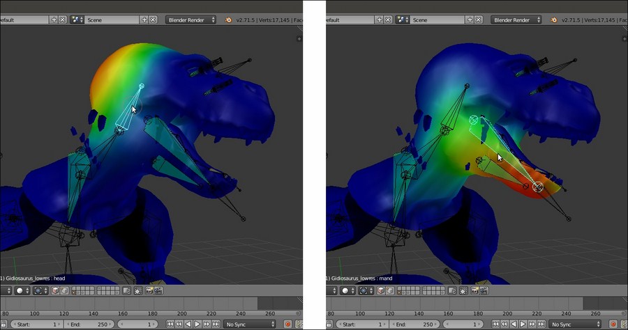
Different weights of the vertex groups associated with different bones
Obviously, this isn't the tool's fault, but it is an unavoidable issue due to the particular arrangement of the bones in the head area and can be quite easily fixed anyway; we'll see how in the next and the Editing the Weight Groups by the Weight Paint tool recipe.
Getting ready
Start Blender and open the Gidiosaurus_rig_from_scratch_02.blend file.
- Select the Armature item in the Outliner and press Ctrl + Tab to go out of Pose Mode and enter Object Mode.
- Go to the Armature window under the Properties sidepanel to switch the Display mode from Wire to Octahedral and deselect the Shapes item.
- Enable the third Armature layer by clicking on the 3rd button under the Skeleton subpanel.
- Disable the 13th scene layer to hide the Armor.
- Go in to Edit Mode and Shift multi-select the MAIN bone, the pole bones and the ctrl bones; in short, all the bones that don't have to deform anything, but are used to control the rig. Press Shift + W and in the Toggle Bone Options pop-up panel, select the Deform item to disable it for all of them at once:
Toggling the Deform item for all the selected bones at once
- Now, deselect everything and select all the bones that, in the previous chapter, we had added specially to rig the Armor object, using the Armature Layers buttons: the armor_ctrl bone, groinguard, vanbrace.L and .R, greaves.L and .R, kneeguard.L and .R, spaulder.L and .R; again, press Shift + W | Deform to disable the option.
Repeating for the Armor object bones
- Don't deselect the Armor bones, simply switch from Edit Mode to Object Mode.
- Select the Gidiosaurus_lowres object and then Shift-select the Armature, and press Ctrl + P; in the Set Parent To pop-up menu; select the With Automatic Weights item:
The Set Parent To pop-up menu
- Reselect the Armature, go in to Edit Mode, and press Shift + W | Deform to re-enable the item for the still-selected Armor bones; then, go out of Edit Mode.
- Now, reselect the Gidiosaurus object; go to the Object Modifiers window, move the newly created Armature modifier upwards in the stack, and enable the Preserve Volume item.
- Disable the Display modifier in viewport button (the one with the eye icon) of the Subdivision Surface modifier to speed up the 3D viewport (sadly, Blender still has very bad real-time viewport performances, so even if you have a lot of RAM and a powerful workstation, it's wise to stay as light as you can).
- Select the Armature and under the Object Data window, re-enable the Shapes item and hide the second and the third Armature Layer; press Ctrl + Tab to go in Pose Mode and try to select some of the control bones to move or rotate them and so control how they are deforming the mesh; temporarily, hide the Eyes object in the Outliner.
The Armature modifier subpanel and the posed mesh
To rotate the bones on their local axis, enable the 3D manipulator widget in the 3D view toolbar (Ctrl + Spacebar), click on the Rotate icon, and set Transformation Orientation to Normal.
- Save the file as
Gidiosaurus_autoweights.blend.
The Automatic Weights tool creates the necessary Vertex Groups based only on the bones that have been set as Deformers in the subpanel under the Bone window. It then assigns weights inside a range from 0.000 to 1.000 to the vertices contained in these vertex groups, calculating their proximity to the bone with the same name. In short, the arm.L bone will deform only the vertices inside the arm.L vertex group, and with an intensity based on their weights.
Because we used the Automatic Weights tool to skin only the sole Gidiosaurus mesh (leaving the skinning of other objects such as the Eyes or the Armor for the next recipe and method), before the parenting we had to check for any bone erroneously left as a deformer (that is, one of the several control bones in the previous chapter), but, especially we had to temporarily disable the Deform item for the Armor bones, which otherwise would have also been evaluated by the tool for the body.
In most cases, the Automatic Weights tool can give quite good results without the need of further tweaking; however in some areas, for example the head, where the head bone length doesn't fully fit the upper part of the shape of the mesh and where there are also other deforming bones, it can easily fail.
Look at the following screenshot; at first, by rotating the head control, the only issue seems to be some of the teeth left out from the calculations but then, simply by moving the controls for the eyes, tongue, and jaw, it becomes evident that the tool assigned several vertices to the wrong bones merely based on their proximity to that part of the mesh:
The failure of the Automatic Weights tool parenting
Although at first sight this can appear to be a total mess, it's usually less complex to fix than one might think.
For the moment, by selecting the Gidiosaurus mesh and pressing Ctrl + Tab, we go in to Weight Paint mode, and by right-clicking on a bone (the Armature is still in Pose Mode), the weights of the corresponding vertex group became visible as colored areas on the mesh; the color red corresponds to a weight value of 1.000 and blue to a value of 0.000, with all the intermediate hues corresponding to the intermediate values. For example, green = 0.500 and so on.
Let's see all this step by step:
- Select the Armature and, while still in Pose Mode, enable the visibility of the third Armature layer (and therefore of all the deforming bones) and then disable the Shapes item again.
- Select the Gidiosaurus mesh and by pressing Ctrl + Tab, enter Weight Paint mode (or switch to it by the object interaction mode button on the toolbar of the 3D view).
- Click on any one of the deforming bones, for example the neck bone, and notice that while the weights appear on the mesh surface, at the same time the corresponding vertex group is highlighted in the Vertex Groups subpanel to the right:
Visualizing the vertex groups on the mesh
By clicking on the head bone and/or the mand bone, the reasons for the bad deformations are immediately clear: the Automatic Weights tool didn't assign the whole upper part of the head of the character to the sole head vertex group (and therefore to the bone with the same name) with a full value of 1.000; instead, it assigned part of the head mesh to the eyes bones, other parts to the tongue.005 bone, some to the mand bone, and so on.
Different weights of the vertex groups associated with different bones
Obviously, this isn't the tool's fault, but it is an unavoidable issue due to the particular arrangement of the bones in the head area and can be quite easily fixed anyway; we'll see how in the next and the Editing the Weight Groups by the Weight Paint tool recipe.
How to do it…
- Select the Gidiosaurus_lowres object and then Shift-select the Armature, and press Ctrl + P; in the Set Parent To pop-up menu; select the With Automatic Weights item:
The Set Parent To pop-up menu
- Reselect the Armature, go in to Edit Mode, and press Shift + W | Deform to re-enable the item for the still-selected Armor bones; then, go out of Edit Mode.
- Now, reselect the Gidiosaurus object; go to the Object Modifiers window, move the newly created Armature modifier upwards in the stack, and enable the Preserve Volume item.
- Disable the Display modifier in viewport button (the one with the eye icon) of the Subdivision Surface modifier to speed up the 3D viewport (sadly, Blender still has very bad real-time viewport performances, so even if you have a lot of RAM and a powerful workstation, it's wise to stay as light as you can).
- Select the Armature and under the Object Data window, re-enable the Shapes item and hide the second and the third Armature Layer; press Ctrl + Tab to go in Pose Mode and try to select some of the control bones to move or rotate them and so control how they are deforming the mesh; temporarily, hide the Eyes object in the Outliner.
The Armature modifier subpanel and the posed mesh
To rotate the bones on their local axis, enable the 3D manipulator widget in the 3D view toolbar (Ctrl + Spacebar), click on the Rotate icon, and set Transformation Orientation to Normal.
- Save the file as
Gidiosaurus_autoweights.blend.
The Automatic Weights tool creates the necessary Vertex Groups based only on the bones that have been set as Deformers in the subpanel under the Bone window. It then assigns weights inside a range from 0.000 to 1.000 to the vertices contained in these vertex groups, calculating their proximity to the bone with the same name. In short, the arm.L bone will deform only the vertices inside the arm.L vertex group, and with an intensity based on their weights.
Because we used the Automatic Weights tool to skin only the sole Gidiosaurus mesh (leaving the skinning of other objects such as the Eyes or the Armor for the next recipe and method), before the parenting we had to check for any bone erroneously left as a deformer (that is, one of the several control bones in the previous chapter), but, especially we had to temporarily disable the Deform item for the Armor bones, which otherwise would have also been evaluated by the tool for the body.
In most cases, the Automatic Weights tool can give quite good results without the need of further tweaking; however in some areas, for example the head, where the head bone length doesn't fully fit the upper part of the shape of the mesh and where there are also other deforming bones, it can easily fail.
Look at the following screenshot; at first, by rotating the head control, the only issue seems to be some of the teeth left out from the calculations but then, simply by moving the controls for the eyes, tongue, and jaw, it becomes evident that the tool assigned several vertices to the wrong bones merely based on their proximity to that part of the mesh:
The failure of the Automatic Weights tool parenting
Although at first sight this can appear to be a total mess, it's usually less complex to fix than one might think.
For the moment, by selecting the Gidiosaurus mesh and pressing Ctrl + Tab, we go in to Weight Paint mode, and by right-clicking on a bone (the Armature is still in Pose Mode), the weights of the corresponding vertex group became visible as colored areas on the mesh; the color red corresponds to a weight value of 1.000 and blue to a value of 0.000, with all the intermediate hues corresponding to the intermediate values. For example, green = 0.500 and so on.
Let's see all this step by step:
- Select the Armature and, while still in Pose Mode, enable the visibility of the third Armature layer (and therefore of all the deforming bones) and then disable the Shapes item again.
- Select the Gidiosaurus mesh and by pressing Ctrl + Tab, enter Weight Paint mode (or switch to it by the object interaction mode button on the toolbar of the 3D view).
- Click on any one of the deforming bones, for example the neck bone, and notice that while the weights appear on the mesh surface, at the same time the corresponding vertex group is highlighted in the Vertex Groups subpanel to the right:
Visualizing the vertex groups on the mesh
By clicking on the head bone and/or the mand bone, the reasons for the bad deformations are immediately clear: the Automatic Weights tool didn't assign the whole upper part of the head of the character to the sole head vertex group (and therefore to the bone with the same name) with a full value of 1.000; instead, it assigned part of the head mesh to the eyes bones, other parts to the tongue.005 bone, some to the mand bone, and so on.
Different weights of the vertex groups associated with different bones
Obviously, this isn't the tool's fault, but it is an unavoidable issue due to the particular arrangement of the bones in the head area and can be quite easily fixed anyway; we'll see how in the next and the Editing the Weight Groups by the Weight Paint tool recipe.
How it works…
The Automatic Weights tool creates the necessary Vertex Groups based only on the bones that have been set as Deformers in the subpanel under the Bone window. It then assigns weights inside a range from 0.000 to 1.000 to the vertices contained in these vertex groups, calculating their proximity to the bone with the same name. In short, the arm.L bone will deform only the vertices inside the arm.L vertex group, and with an intensity based on their weights.
Because we used the Automatic Weights tool to skin only the sole Gidiosaurus mesh (leaving the skinning of other objects such as the Eyes or the Armor for the next recipe and method), before the parenting we had to check for any bone erroneously left as a deformer (that is, one of the several control bones in the previous chapter), but, especially we had to temporarily disable the Deform item for the Armor bones, which otherwise would have also been evaluated by the tool for the body.
In most cases, the Automatic Weights tool can give quite good results without the need of further tweaking; however in some areas, for example the head, where the head bone length doesn't fully fit the upper part of the shape of the mesh and where there are also other deforming bones, it can easily fail.
Look at the following screenshot; at first, by rotating the head control, the only issue seems to be some of the teeth left out from the calculations but then, simply by moving the controls for the eyes, tongue, and jaw, it becomes evident that the tool assigned several vertices to the wrong bones merely based on their proximity to that part of the mesh:
The failure of the Automatic Weights tool parenting
Although at first sight this can appear to be a total mess, it's usually less complex to fix than one might think.
For the moment, by selecting the Gidiosaurus mesh and pressing Ctrl + Tab, we go in to Weight Paint mode, and by right-clicking on a bone (the Armature is still in Pose Mode), the weights of the corresponding vertex group became visible as colored areas on the mesh; the color red corresponds to a weight value of 1.000 and blue to a value of 0.000, with all the intermediate hues corresponding to the intermediate values. For example, green = 0.500 and so on.
Let's see all this step by step:
- Select the Armature and, while still in Pose Mode, enable the visibility of the third Armature layer (and therefore of all the deforming bones) and then disable the Shapes item again.
- Select the Gidiosaurus mesh and by pressing Ctrl + Tab, enter Weight Paint mode (or switch to it by the object interaction mode button on the toolbar of the 3D view).
- Click on any one of the deforming bones, for example the neck bone, and notice that while the weights appear on the mesh surface, at the same time the corresponding vertex group is highlighted in the Vertex Groups subpanel to the right:
Visualizing the vertex groups on the mesh
By clicking on the head bone and/or the mand bone, the reasons for the bad deformations are immediately clear: the Automatic Weights tool didn't assign the whole upper part of the head of the character to the sole head vertex group (and therefore to the bone with the same name) with a full value of 1.000; instead, it assigned part of the head mesh to the eyes bones, other parts to the tongue.005 bone, some to the mand bone, and so on.
Different weights of the vertex groups associated with different bones
Obviously, this isn't the tool's fault, but it is an unavoidable issue due to the particular arrangement of the bones in the head area and can be quite easily fixed anyway; we'll see how in the next and the Editing the Weight Groups by the Weight Paint tool recipe.
There's more…
Let's see all this step by step:
- Select the Armature and, while still in Pose Mode, enable the visibility of the third Armature layer (and therefore of all the deforming bones) and then disable the Shapes item again.
- Select the Gidiosaurus mesh and by pressing Ctrl + Tab, enter Weight Paint mode (or switch to it by the object interaction mode button on the toolbar of the 3D view).
- Click on any one of the deforming bones, for example the neck bone, and notice that while the weights appear on the mesh surface, at the same time the corresponding vertex group is highlighted in the Vertex Groups subpanel to the right:
Visualizing the vertex groups on the mesh
By clicking on the head bone and/or the mand bone, the reasons for the bad deformations are immediately clear: the Automatic Weights tool didn't assign the whole upper part of the head of the character to the sole head vertex group (and therefore to the bone with the same name) with a full value of 1.000; instead, it assigned part of the head mesh to the eyes bones, other parts to the tongue.005 bone, some to the mand bone, and so on.
Different weights of the vertex groups associated with different bones
Obviously, this isn't the tool's fault, but it is an unavoidable issue due to the particular arrangement of the bones in the head area and can be quite easily fixed anyway; we'll see how in the next and the Editing the Weight Groups by the Weight Paint tool recipe.
This technique is the oldest way to assign weights to vertices groups in Blender. Although now there are quicker ways to do the same thing, in some cases it's still one of the best approaches, which can reveal itself to be quite useful mainly because you can precisely select individual or edge-loops of vertices to be weighted inside a group.
Open the Gidiosaurus_autoweights.blend file we saved in the previous recipe.
- If necessary, press Ctrl + Tab to go out of Weight Paint mode.
- Select the Armature (which should still be in Pose Mode), press the A key twice to deselect-select all the bones, and press Alt + R and Alt + G to clear any rotation or position and restore the default pose.
- Press the 3 key on the numpad to go in to Side view; if necessary, the 5 key on the numpad to go in to Ortho view and the Z key to go in to Wireframe viewport shading mode.
- Select the Armature and disable the Shapes item; switch the draw mode of the bones to Stick and enable the third Armature layer to show the deforming bones.
- Save the file as
Gidiosaurus_skinning_01.blend.
First, we are going to use this technique to fix the head deformation as follows:
- Press Shift + B to draw a box around the head of the Gidiosaurus mesh and automatically zoom to it. Select the mesh and enter Edit Mode.
- Press the C key, through which the mouse cursor turns into a circle whose diameter can be set by scrolling the mouse wheel.
- Start to paint-select the vertices you want to add to the vertex group; in this case, we must add the whole upper head to the head vertex group and also include the upper teeth that were missing in the group.
- Be sure that the head vertex group is the selected one in the Vertex Groups subpanel under the Object Data window to the right, and that the Weight slider is set to 1.000; then, click on the Assign button.
- To quickly find a required vertex group, instead of slowly scrolling the list, just click on the grayed out little + icon at the bottom of the Vertex Groups window (just above the Assign button) to expand a blank search field and then write a few letters of the group's name followed by the Enter key:

The vertex group names search function
To get the complete list of vertex groups' names back, just erase the letters you wrote in the field and press Enter.
- Now, switch from Edit Mode to Weight Paint mode again, where the head vertex group colors show a lot different than before:

The modified "head" vertex group
- Now, while still in Weight Paint mode, go to the Tools tab under the Tool Shelf to the left of the screen and, in the Weight Tools subpanel, first click on the Normalize All button and then on the Clean button.
- Select the mand bone, go in to Edit Mode, and press A to deselect the vertices of the head vertex group. Select all the vertices of the jaw, including the bottom teeth; then go to the Vertex Groups subpanel to the right and deselect the tongue group by clicking on the, yes, Deselect button (we created the tongue vertex group chapters ago, during the modeling stage; otherwise, just deselect the tongue's edge-loops manually).
- Find and select the mand group and click on the Assign button.
- Go again in to Weight Paint mode and click on the Normalize All and Clean buttons under the Weight Tools subpanel:

The Weight Tools subpanel and the "mand" vertex group
- Now, go out of Weight Paint mode, select the mesh and, in the Vertex Groups subpanel, search for the eyelid_upper.L vertex group; enter Edit Mode and click on the Select button:

The selected eyelid_upper.L vertex group
We must get rid of all these vertices erroneously assigned to the vertex group by the Automatic Weights tool.
- Click on the Remove button and then press the A key to deselect everything.
- Repeat this for the eyelid_bottom.L, eyelid_upper.R, eyelid_bottom.R, and also for the eye.L and eye.R vertex groups.
- Zoom to the eyes area. Select an edge-loop (Alt + right-click) around the left eyelids and then press Ctrl and the + key on the numpad to extend the selection; press the H key to hide the selected vertices (this is simply to isolate the eyelids vertices for easier edge-loops selection):

Isolating the eyelids vertices
- Select the border upper edge-loops and assign them to the eyelid_upper.L vertex group with a weight of 1.000; select the second upper edge-loop and again assign it to the eyelid_upper.L vertex group, but with a weight of 0.500 (see the following screenshot).
- Do the same for eyelid_bottom.L:

The visualization of the eyelids vertex group with different weights
In the preceding screenshot, to the right, you can see the weights of eyelid_upper and eyelid_bottom vertex groups on both sides, made visible at the same time by the Multi-Paint item enabled in the Brush subpanel under the Tool Shelf; here it is used only for visualization purposes.
- Repeat the procedure for the eyelids on the right side (eyelid_upper.R and eyelid_bottom.R).
- In the Vertex Groups subpanel, select the head vertex group and then select the border edge-loops of both the left and right eyelids. Click on the Remove button to remove those vertices from the group's evaluation:

Removing the eyelids vertices from the "head" vertex group
Assigning weights by hand can be a handy method also for other parts, for example, the eyeballs, which are separate objects from the Gidiosaurus mesh.
- Go out of Edit Mode, and in the Outliner select the Eyes object; press Tab again to go in to Edit Mode.
- Go in to Front view and box-select all the vertices of the left eye; then, go to the Vertex Groups subpanel under the Object Data window and click on the + icon to the right to create a new group:

Creating the vertex group for the eyeball
- Ctrl + left-click on the name of the vertex group to rename it as eye.L and then click on the Assign button to assign all the selected vertices to the group with a value of 1.000.
- Deselect everything, select the vertices of the other eye, and create a new vertex group; rename it as eye.R and assign the vertices.

Creating the eye.R vertex group
- Exit Edit Mode (Tab) and go to the Object Modifier window; assign an Armature modifier, move it upwards in the stack, and click on the Object field to select the Armature item as a deforming object.
- Temporarily, unhide the Corneas object in the Outliner and repeat from step 19 to step 23, where we created the eye.L and eye.R vertex groups and assigned the appropriate mesh vertices and the Armature modifier.
The same process must be applied to the skinning of the Armor that, being a single object made of stiff elements, can be easily and ideally divided into different vertex groups; each one is skinned with the full value of 1.000.
- Click on the button to activate the 13th scene layer and show the Armor; select it and enter Edit Mode.
- Select all the vertices of the helm, including the decorations, create the head vertex group in the Armor mesh (remember that the name must be the one of the deforming bones), and click on the Assign button with a weight value of 1.000:

The "head" vertex group for the Armor object
- Repeat the operation with each part of the Armor, so creating, always with a weight of 1.000, the vertex groups: vanbrace.L and vanbrace.R (covering the forearms), greave.L and .R (covering the calves), groinguard (the front hips), kneeguard.L and .R, spaulder.L and .R, and armor_ctrl.
You can use the following screenshot as a guide:

The happy colorful Armor guideline
- Go out of Edit Mode; then, go to the Object Modifier window, assign an Armature modifier to the Armor, move it upwards in the stack, and click on the Object field to select the Armature item as a deforming object.
- Disable the Display modifier in viewport button (the one with the eye icon) for the Subdivision Surface modifier, to speed up the 3D viewport.
For the moment, ignore the Tiers (which have been separated by the Armor object and simplified by deleting several alternate edge-loops, this we'll skin in the next recipe) and save the file.
The Normalize All button normalizes the weights of all the vertex groups so that their sum is not superior to 1.000; because we had assigned a weight of 1.000 to the upper head vertices, the vertices in the other groups that were interfering with the head deformation have been automatically set to 0.000.
The head group, instead, remained the same because it was locked in the Options bottom panel; the Clean button, then, took care of removing all the unwanted vertices in the active group, restricting the inclusion of its vertices only to those with a weight greater than 0.000.
When assigning vertices to a group, the Weight slider under the Vertex Groups subpanel can obviously be set to any value between 0.000 and 1.000, so it's also possible to select a single edge-loop or rows of vertices and assign them at different times to the same vertex groups, but with different weight values. For example, a central edge-loop of vertices with the weight of 1.000 can be surrounded by external edge-loops with weight values of 0.750, 0.500, 0.250, and so on. This is what we have done for the eyelids after the cleaning of the eye sockets area, thanks to the Select, Deselect and Remove buttons. Be aware that the same result can be obtained by painting and/or blurring the weights on the mesh, but we'll see this in the next recipe.
Getting ready
Open the Gidiosaurus_autoweights.blend file we saved in the previous recipe.
- If necessary, press Ctrl + Tab to go out of Weight Paint mode.
- Select the Armature (which should still be in Pose Mode), press the A key twice to deselect-select all the bones, and press Alt + R and Alt + G to clear any rotation or position and restore the default pose.
- Press the 3 key on the numpad to go in to Side view; if necessary, the 5 key on the numpad to go in to Ortho view and the Z key to go in to Wireframe viewport shading mode.
- Select the Armature and disable the Shapes item; switch the draw mode of the bones to Stick and enable the third Armature layer to show the deforming bones.
- Save the file as
Gidiosaurus_skinning_01.blend.
First, we are going to use this technique to fix the head deformation as follows:
- Press Shift + B to draw a box around the head of the Gidiosaurus mesh and automatically zoom to it. Select the mesh and enter Edit Mode.
- Press the C key, through which the mouse cursor turns into a circle whose diameter can be set by scrolling the mouse wheel.
- Start to paint-select the vertices you want to add to the vertex group; in this case, we must add the whole upper head to the head vertex group and also include the upper teeth that were missing in the group.
- Be sure that the head vertex group is the selected one in the Vertex Groups subpanel under the Object Data window to the right, and that the Weight slider is set to 1.000; then, click on the Assign button.
- To quickly find a required vertex group, instead of slowly scrolling the list, just click on the grayed out little + icon at the bottom of the Vertex Groups window (just above the Assign button) to expand a blank search field and then write a few letters of the group's name followed by the Enter key:
The vertex group names search function
To get the complete list of vertex groups' names back, just erase the letters you wrote in the field and press Enter.
- Now, switch from Edit Mode to Weight Paint mode again, where the head vertex group colors show a lot different than before:
The modified "head" vertex group
- Now, while still in Weight Paint mode, go to the Tools tab under the Tool Shelf to the left of the screen and, in the Weight Tools subpanel, first click on the Normalize All button and then on the Clean button.
- Select the mand bone, go in to Edit Mode, and press A to deselect the vertices of the head vertex group. Select all the vertices of the jaw, including the bottom teeth; then go to the Vertex Groups subpanel to the right and deselect the tongue group by clicking on the, yes, Deselect button (we created the tongue vertex group chapters ago, during the modeling stage; otherwise, just deselect the tongue's edge-loops manually).
- Find and select the mand group and click on the Assign button.
- Go again in to Weight Paint mode and click on the Normalize All and Clean buttons under the Weight Tools subpanel:
The Weight Tools subpanel and the "mand" vertex group
- Now, go out of Weight Paint mode, select the mesh and, in the Vertex Groups subpanel, search for the eyelid_upper.L vertex group; enter Edit Mode and click on the Select button:
The selected eyelid_upper.L vertex group
We must get rid of all these vertices erroneously assigned to the vertex group by the Automatic Weights tool.
- Click on the Remove button and then press the A key to deselect everything.
- Repeat this for the eyelid_bottom.L, eyelid_upper.R, eyelid_bottom.R, and also for the eye.L and eye.R vertex groups.
- Zoom to the eyes area. Select an edge-loop (Alt + right-click) around the left eyelids and then press Ctrl and the + key on the numpad to extend the selection; press the H key to hide the selected vertices (this is simply to isolate the eyelids vertices for easier edge-loops selection):
Isolating the eyelids vertices
- Select the border upper edge-loops and assign them to the eyelid_upper.L vertex group with a weight of 1.000; select the second upper edge-loop and again assign it to the eyelid_upper.L vertex group, but with a weight of 0.500 (see the following screenshot).
- Do the same for eyelid_bottom.L:
The visualization of the eyelids vertex group with different weights
In the preceding screenshot, to the right, you can see the weights of eyelid_upper and eyelid_bottom vertex groups on both sides, made visible at the same time by the Multi-Paint item enabled in the Brush subpanel under the Tool Shelf; here it is used only for visualization purposes.
- Repeat the procedure for the eyelids on the right side (eyelid_upper.R and eyelid_bottom.R).
- In the Vertex Groups subpanel, select the head vertex group and then select the border edge-loops of both the left and right eyelids. Click on the Remove button to remove those vertices from the group's evaluation:
Removing the eyelids vertices from the "head" vertex group
Assigning weights by hand can be a handy method also for other parts, for example, the eyeballs, which are separate objects from the Gidiosaurus mesh.
- Go out of Edit Mode, and in the Outliner select the Eyes object; press Tab again to go in to Edit Mode.
- Go in to Front view and box-select all the vertices of the left eye; then, go to the Vertex Groups subpanel under the Object Data window and click on the + icon to the right to create a new group:
Creating the vertex group for the eyeball
- Ctrl + left-click on the name of the vertex group to rename it as eye.L and then click on the Assign button to assign all the selected vertices to the group with a value of 1.000.
- Deselect everything, select the vertices of the other eye, and create a new vertex group; rename it as eye.R and assign the vertices.
Creating the eye.R vertex group
- Exit Edit Mode (Tab) and go to the Object Modifier window; assign an Armature modifier, move it upwards in the stack, and click on the Object field to select the Armature item as a deforming object.
- Temporarily, unhide the Corneas object in the Outliner and repeat from step 19 to step 23, where we created the eye.L and eye.R vertex groups and assigned the appropriate mesh vertices and the Armature modifier.
The same process must be applied to the skinning of the Armor that, being a single object made of stiff elements, can be easily and ideally divided into different vertex groups; each one is skinned with the full value of 1.000.
- Click on the button to activate the 13th scene layer and show the Armor; select it and enter Edit Mode.
- Select all the vertices of the helm, including the decorations, create the head vertex group in the Armor mesh (remember that the name must be the one of the deforming bones), and click on the Assign button with a weight value of 1.000:
The "head" vertex group for the Armor object
- Repeat the operation with each part of the Armor, so creating, always with a weight of 1.000, the vertex groups: vanbrace.L and vanbrace.R (covering the forearms), greave.L and .R (covering the calves), groinguard (the front hips), kneeguard.L and .R, spaulder.L and .R, and armor_ctrl.
You can use the following screenshot as a guide:
The happy colorful Armor guideline
- Go out of Edit Mode; then, go to the Object Modifier window, assign an Armature modifier to the Armor, move it upwards in the stack, and click on the Object field to select the Armature item as a deforming object.
- Disable the Display modifier in viewport button (the one with the eye icon) for the Subdivision Surface modifier, to speed up the 3D viewport.
For the moment, ignore the Tiers (which have been separated by the Armor object and simplified by deleting several alternate edge-loops, this we'll skin in the next recipe) and save the file.
The Normalize All button normalizes the weights of all the vertex groups so that their sum is not superior to 1.000; because we had assigned a weight of 1.000 to the upper head vertices, the vertices in the other groups that were interfering with the head deformation have been automatically set to 0.000.
The head group, instead, remained the same because it was locked in the Options bottom panel; the Clean button, then, took care of removing all the unwanted vertices in the active group, restricting the inclusion of its vertices only to those with a weight greater than 0.000.
When assigning vertices to a group, the Weight slider under the Vertex Groups subpanel can obviously be set to any value between 0.000 and 1.000, so it's also possible to select a single edge-loop or rows of vertices and assign them at different times to the same vertex groups, but with different weight values. For example, a central edge-loop of vertices with the weight of 1.000 can be surrounded by external edge-loops with weight values of 0.750, 0.500, 0.250, and so on. This is what we have done for the eyelids after the cleaning of the eye sockets area, thanks to the Select, Deselect and Remove buttons. Be aware that the same result can be obtained by painting and/or blurring the weights on the mesh, but we'll see this in the next recipe.
How to do it…
First, we are going to use this technique to fix the head deformation as follows:
- Press Shift + B to draw a box around the head of the Gidiosaurus mesh and automatically zoom to it. Select the mesh and enter Edit Mode.
- Press the C key, through which the mouse cursor turns into a circle whose diameter can be set by scrolling the mouse wheel.
- Start to paint-select the vertices you want to add to the vertex group; in this case, we must add the whole upper head to the head vertex group and also include the upper teeth that were missing in the group.
- Be sure that the head vertex group is the selected one in the Vertex Groups subpanel under the Object Data window to the right, and that the Weight slider is set to 1.000; then, click on the Assign button.
- To quickly find a required vertex group, instead of slowly scrolling the list, just click on the grayed out little + icon at the bottom of the Vertex Groups window (just above the Assign button) to expand a blank search field and then write a few letters of the group's name followed by the Enter key:
The vertex group names search function
To get the complete list of vertex groups' names back, just erase the letters you wrote in the field and press Enter.
- Now, switch from Edit Mode to Weight Paint mode again, where the head vertex group colors show a lot different than before:
The modified "head" vertex group
- Now, while still in Weight Paint mode, go to the Tools tab under the Tool Shelf to the left of the screen and, in the Weight Tools subpanel, first click on the Normalize All button and then on the Clean button.
- Select the mand bone, go in to Edit Mode, and press A to deselect the vertices of the head vertex group. Select all the vertices of the jaw, including the bottom teeth; then go to the Vertex Groups subpanel to the right and deselect the tongue group by clicking on the, yes, Deselect button (we created the tongue vertex group chapters ago, during the modeling stage; otherwise, just deselect the tongue's edge-loops manually).
- Find and select the mand group and click on the Assign button.
- Go again in to Weight Paint mode and click on the Normalize All and Clean buttons under the Weight Tools subpanel:
The Weight Tools subpanel and the "mand" vertex group
- Now, go out of Weight Paint mode, select the mesh and, in the Vertex Groups subpanel, search for the eyelid_upper.L vertex group; enter Edit Mode and click on the Select button:
The selected eyelid_upper.L vertex group
We must get rid of all these vertices erroneously assigned to the vertex group by the Automatic Weights tool.
- Click on the Remove button and then press the A key to deselect everything.
- Repeat this for the eyelid_bottom.L, eyelid_upper.R, eyelid_bottom.R, and also for the eye.L and eye.R vertex groups.
- Zoom to the eyes area. Select an edge-loop (Alt + right-click) around the left eyelids and then press Ctrl and the + key on the numpad to extend the selection; press the H key to hide the selected vertices (this is simply to isolate the eyelids vertices for easier edge-loops selection):
Isolating the eyelids vertices
- Select the border upper edge-loops and assign them to the eyelid_upper.L vertex group with a weight of 1.000; select the second upper edge-loop and again assign it to the eyelid_upper.L vertex group, but with a weight of 0.500 (see the following screenshot).
- Do the same for eyelid_bottom.L:
The visualization of the eyelids vertex group with different weights
In the preceding screenshot, to the right, you can see the weights of eyelid_upper and eyelid_bottom vertex groups on both sides, made visible at the same time by the Multi-Paint item enabled in the Brush subpanel under the Tool Shelf; here it is used only for visualization purposes.
- Repeat the procedure for the eyelids on the right side (eyelid_upper.R and eyelid_bottom.R).
- In the Vertex Groups subpanel, select the head vertex group and then select the border edge-loops of both the left and right eyelids. Click on the Remove button to remove those vertices from the group's evaluation:
Removing the eyelids vertices from the "head" vertex group
Assigning weights by hand can be a handy method also for other parts, for example, the eyeballs, which are separate objects from the Gidiosaurus mesh.
- Go out of Edit Mode, and in the Outliner select the Eyes object; press Tab again to go in to Edit Mode.
- Go in to Front view and box-select all the vertices of the left eye; then, go to the Vertex Groups subpanel under the Object Data window and click on the + icon to the right to create a new group:
Creating the vertex group for the eyeball
- Ctrl + left-click on the name of the vertex group to rename it as eye.L and then click on the Assign button to assign all the selected vertices to the group with a value of 1.000.
- Deselect everything, select the vertices of the other eye, and create a new vertex group; rename it as eye.R and assign the vertices.
Creating the eye.R vertex group
- Exit Edit Mode (Tab) and go to the Object Modifier window; assign an Armature modifier, move it upwards in the stack, and click on the Object field to select the Armature item as a deforming object.
- Temporarily, unhide the Corneas object in the Outliner and repeat from step 19 to step 23, where we created the eye.L and eye.R vertex groups and assigned the appropriate mesh vertices and the Armature modifier.
The same process must be applied to the skinning of the Armor that, being a single object made of stiff elements, can be easily and ideally divided into different vertex groups; each one is skinned with the full value of 1.000.
- Click on the button to activate the 13th scene layer and show the Armor; select it and enter Edit Mode.
- Select all the vertices of the helm, including the decorations, create the head vertex group in the Armor mesh (remember that the name must be the one of the deforming bones), and click on the Assign button with a weight value of 1.000:
The "head" vertex group for the Armor object
- Repeat the operation with each part of the Armor, so creating, always with a weight of 1.000, the vertex groups: vanbrace.L and vanbrace.R (covering the forearms), greave.L and .R (covering the calves), groinguard (the front hips), kneeguard.L and .R, spaulder.L and .R, and armor_ctrl.
You can use the following screenshot as a guide:
The happy colorful Armor guideline
- Go out of Edit Mode; then, go to the Object Modifier window, assign an Armature modifier to the Armor, move it upwards in the stack, and click on the Object field to select the Armature item as a deforming object.
- Disable the Display modifier in viewport button (the one with the eye icon) for the Subdivision Surface modifier, to speed up the 3D viewport.
For the moment, ignore the Tiers (which have been separated by the Armor object and simplified by deleting several alternate edge-loops, this we'll skin in the next recipe) and save the file.
The Normalize All button normalizes the weights of all the vertex groups so that their sum is not superior to 1.000; because we had assigned a weight of 1.000 to the upper head vertices, the vertices in the other groups that were interfering with the head deformation have been automatically set to 0.000.
The head group, instead, remained the same because it was locked in the Options bottom panel; the Clean button, then, took care of removing all the unwanted vertices in the active group, restricting the inclusion of its vertices only to those with a weight greater than 0.000.
When assigning vertices to a group, the Weight slider under the Vertex Groups subpanel can obviously be set to any value between 0.000 and 1.000, so it's also possible to select a single edge-loop or rows of vertices and assign them at different times to the same vertex groups, but with different weight values. For example, a central edge-loop of vertices with the weight of 1.000 can be surrounded by external edge-loops with weight values of 0.750, 0.500, 0.250, and so on. This is what we have done for the eyelids after the cleaning of the eye sockets area, thanks to the Select, Deselect and Remove buttons. Be aware that the same result can be obtained by painting and/or blurring the weights on the mesh, but we'll see this in the next recipe.
How it works…
The Normalize All button normalizes the weights of all the vertex groups so that their sum is not superior to 1.000; because we had assigned a weight of 1.000 to the upper head vertices, the vertices in the other groups that were interfering with the head deformation have been automatically set to 0.000.
The head group, instead, remained the same because it was locked in the Options bottom panel; the Clean button, then, took care of removing all the unwanted vertices in the active group, restricting the inclusion of its vertices only to those with a weight greater than 0.000.
When assigning vertices to a group, the Weight slider under the Vertex Groups subpanel can obviously be set to any value between 0.000 and 1.000, so it's also possible to select a single edge-loop or rows of vertices and assign them at different times to the same vertex groups, but with different weight values. For example, a central edge-loop of vertices with the weight of 1.000 can be surrounded by external edge-loops with weight values of 0.750, 0.500, 0.250, and so on. This is what we have done for the eyelids after the cleaning of the eye sockets area, thanks to the Select, Deselect and Remove buttons. Be aware that the same result can be obtained by painting and/or blurring the weights on the mesh, but we'll see this in the next recipe.
Both the Automatic Weights parenting as well as the Weight Groups created and assigned by hand must, at a certain point, inevitably be edited for several reasons. As we have already seen, the parenting tool didn't do a perfect job, or maybe the transition between different weights is too sharp and must be blurred to smoothly deform the mesh. In any case, the ideal tool for this editing work is the Weight Paint tool.
As usual, let's first prepare the scene to work on:
- Open the
Gidiosaurus_skinning_01.blendfile and hide the 13th scene layer. - Enable the 3rd Armature layer and then deselect the Shapes item.
- Press the 3 key on the numpad to go in to Side view; if necessary, press the 5 key on the numpad to go in to Ortho view and the Z key to go in to Wireframe viewport shading mode.
- Save the file as
Gidiosaurus_skinning_02.blend.
Also, now let's start with the Weight Paint tool itself:
- Select the Gidiosaurus mesh and go in to Weight Paint mode; the tabs under the Tool Shelf on the left-hand side of the 3D window (press the T key in case they are not already present), change to show the Weight Paint tools.
- In the viewport, right-click on the head bone to show the head vertex group on the mesh's surface.
- Go to the Tool Shelf and click on the Options tab to verify that the X Mirror item in the Options subpanel is activated. Then, go back to the Tools tab and click on the big Brush window at the top to select a Blur brush; set Weight to 1.000 and Strength to 0.400.
- Select the Auto Normalize item at the bottom of the Brush subpanel.
- Start to paint on the borderline of the vertex group, blurring the separation between the red and blue colors and trying to obtain, in general, a transition as smooth as possible:

Blurring the edges of the vertex group
- Switch to the mand vertex group by selecting the corresponding bone and smooth the transition again:

Smoothing the transition of the "mand" vertex group
- If you need to reduce the weight of a vertex, switch the Blur brush with a Subtract one, and with a low Strength (0.100 or even less) paint on it. Then, if necessary, blur the area again.
- Alternatively, instead of using a Subtract brush, you can paint on the mesh with a Mix brush set with Strength = 1.000 and Weight = 0.000.
- Select the neck bone and reduce the weight of the vertices at the neck edges to 0.000.
- Select the chest bone and paint the vertices at the chest edges to 1.000.
- Repeat the last step also for the spine.001 and .002 bones:

Other vertex groups
To look at exactly how the weights have been edited by the Weight Paint tool, open the
Gidiosaurus_skinning_03.blendfile, hide the Armor, select the Gidiosaurus mesh and press Ctrl + Tab to go in to Weight Paint mode, and then right-click to select the different bones.One last thing still remains to be done: we must also skin the Tiers_simplified object.
- Enable the 13th scene layer to show the Armor and the Tiers; temporarily hide both the Armature and the Armor object by clicking on the respective eye icon in the Outliner.
- Select the Gidiosaurus mesh, then, Shift-select the Tiers object and press Ctrl + Tab to go in to Weight Paint mode.
- Go to the Weight Tool subpanel under the Tool Shelf and click on the Transfer Weight button, which is the last button at the bottom. After a bit of calculation, the weights of the vertices for the underlying Gidiosaurus mesh have been transferred to the corresponding overlaid vertices of the Tiers object and the vertex groups as well:

Transferring the vertex group weights from the Gidiosaurus mesh to the tiers object
- Go out of Weight Paint mode and select the sole Tiers object. In the Object Modifiers window, assign an Armature modifier or, if you prefer, just join it to the Armor object (Armor as an active object and then press Ctrl + J). In both cases, just remember to enable the Preserve Volume item.
- Save the file.
Getting ready
As usual, let's first prepare the scene to work on:
- Open the
Gidiosaurus_skinning_01.blendfile and hide the 13th scene layer. - Enable the 3rd Armature layer and then deselect the Shapes item.
- Press the 3 key on the numpad to go in to Side view; if necessary, press the 5 key on the numpad to go in to Ortho view and the Z key to go in to Wireframe viewport shading mode.
- Save the file as
Gidiosaurus_skinning_02.blend.
Also, now let's start with the Weight Paint tool itself:
- Select the Gidiosaurus mesh and go in to Weight Paint mode; the tabs under the Tool Shelf on the left-hand side of the 3D window (press the T key in case they are not already present), change to show the Weight Paint tools.
- In the viewport, right-click on the head bone to show the head vertex group on the mesh's surface.
- Go to the Tool Shelf and click on the Options tab to verify that the X Mirror item in the Options subpanel is activated. Then, go back to the Tools tab and click on the big Brush window at the top to select a Blur brush; set Weight to 1.000 and Strength to 0.400.
- Select the Auto Normalize item at the bottom of the Brush subpanel.
- Start to paint on the borderline of the vertex group, blurring the separation between the red and blue colors and trying to obtain, in general, a transition as smooth as possible:
Blurring the edges of the vertex group
- Switch to the mand vertex group by selecting the corresponding bone and smooth the transition again:
Smoothing the transition of the "mand" vertex group
- If you need to reduce the weight of a vertex, switch the Blur brush with a Subtract one, and with a low Strength (0.100 or even less) paint on it. Then, if necessary, blur the area again.
- Alternatively, instead of using a Subtract brush, you can paint on the mesh with a Mix brush set with Strength = 1.000 and Weight = 0.000.
- Select the neck bone and reduce the weight of the vertices at the neck edges to 0.000.
- Select the chest bone and paint the vertices at the chest edges to 1.000.
- Repeat the last step also for the spine.001 and .002 bones:
Other vertex groups
To look at exactly how the weights have been edited by the Weight Paint tool, open the
Gidiosaurus_skinning_03.blendfile, hide the Armor, select the Gidiosaurus mesh and press Ctrl + Tab to go in to Weight Paint mode, and then right-click to select the different bones.One last thing still remains to be done: we must also skin the Tiers_simplified object.
- Enable the 13th scene layer to show the Armor and the Tiers; temporarily hide both the Armature and the Armor object by clicking on the respective eye icon in the Outliner.
- Select the Gidiosaurus mesh, then, Shift-select the Tiers object and press Ctrl + Tab to go in to Weight Paint mode.
- Go to the Weight Tool subpanel under the Tool Shelf and click on the Transfer Weight button, which is the last button at the bottom. After a bit of calculation, the weights of the vertices for the underlying Gidiosaurus mesh have been transferred to the corresponding overlaid vertices of the Tiers object and the vertex groups as well:
Transferring the vertex group weights from the Gidiosaurus mesh to the tiers object
- Go out of Weight Paint mode and select the sole Tiers object. In the Object Modifiers window, assign an Armature modifier or, if you prefer, just join it to the Armor object (Armor as an active object and then press Ctrl + J). In both cases, just remember to enable the Preserve Volume item.
- Save the file.
How to do it…
Also, now let's start with the Weight Paint tool itself:
- Select the Gidiosaurus mesh and go in to Weight Paint mode; the tabs under the Tool Shelf on the left-hand side of the 3D window (press the T key in case they are not already present), change to show the Weight Paint tools.
- In the viewport, right-click on the head bone to show the head vertex group on the mesh's surface.
- Go to the Tool Shelf and click on the Options tab to verify that the X Mirror item in the Options subpanel is activated. Then, go back to the Tools tab and click on the big Brush window at the top to select a Blur brush; set Weight to 1.000 and Strength to 0.400.
- Select the Auto Normalize item at the bottom of the Brush subpanel.
- Start to paint on the borderline of the vertex group, blurring the separation between the red and blue colors and trying to obtain, in general, a transition as smooth as possible:
Blurring the edges of the vertex group
- Switch to the mand vertex group by selecting the corresponding bone and smooth the transition again:
Smoothing the transition of the "mand" vertex group
- If you need to reduce the weight of a vertex, switch the Blur brush with a Subtract one, and with a low Strength (0.100 or even less) paint on it. Then, if necessary, blur the area again.
- Alternatively, instead of using a Subtract brush, you can paint on the mesh with a Mix brush set with Strength = 1.000 and Weight = 0.000.
- Select the neck bone and reduce the weight of the vertices at the neck edges to 0.000.
- Select the chest bone and paint the vertices at the chest edges to 1.000.
- Repeat the last step also for the spine.001 and .002 bones:
Other vertex groups
To look at exactly how the weights have been edited by the Weight Paint tool, open the
Gidiosaurus_skinning_03.blendfile, hide the Armor, select the Gidiosaurus mesh and press Ctrl + Tab to go in to Weight Paint mode, and then right-click to select the different bones.One last thing still remains to be done: we must also skin the Tiers_simplified object.
- Enable the 13th scene layer to show the Armor and the Tiers; temporarily hide both the Armature and the Armor object by clicking on the respective eye icon in the Outliner.
- Select the Gidiosaurus mesh, then, Shift-select the Tiers object and press Ctrl + Tab to go in to Weight Paint mode.
- Go to the Weight Tool subpanel under the Tool Shelf and click on the Transfer Weight button, which is the last button at the bottom. After a bit of calculation, the weights of the vertices for the underlying Gidiosaurus mesh have been transferred to the corresponding overlaid vertices of the Tiers object and the vertex groups as well:
Transferring the vertex group weights from the Gidiosaurus mesh to the tiers object
- Go out of Weight Paint mode and select the sole Tiers object. In the Object Modifiers window, assign an Armature modifier or, if you prefer, just join it to the Armor object (Armor as an active object and then press Ctrl + J). In both cases, just remember to enable the Preserve Volume item.
- Save the file.
The Mesh Deform modifier has been introduced in Blender for the production of the short open movie Big Buck Bunny and it's a very easy and quick way to skin medium and high resolution characters' meshes. Although the utility of this modifier really shows the skinning of fat, chubby characters, it will be useful to see the way it works even if applied to a quite skinny character such as the Gidiosaurus.
First, we must prepare the deforming cage, which is a simplified low poly mesh totally enveloping the character's mesh; to do this, in our case, we can start from an already made object:
- Open the
Gidiosaurus_skinning_03.blendfile. - Click on the File | Append menu (or press Shift + F1), browse to the folder with all the project files, and click on the
Gidiosaurus_base_mesh_02.blendfile. Then, click on theObjectfolder and select the Gidiosaurus item. - Move the just-appended object to the first scene layer; then, go to the Outliner and rename it as Gidiosaurus_cage.
- This is the base mesh we built in the first chapter of this book, so go to the Object Modifier window and apply the Skin modifier; delete the Mirror modifier and disable the Subdivision Surface modifier visibility in the viewport by clicking on the eye icon button.
- Go in to Edit Mode and by pressing Ctrl +R, cut a median vertical edge-loop at the center of the mesh.
- Select the vertices of the missing half and delete them; then, select the median edge-loop and, with Pivot Point set to 3D Cursor (and the 3D Cursor located at the center of the scene), scale them to 0.000 along the global x axis.
- Assign a new Mirror modifier and enable the Clipping item.

Preparing the deforming cage
- Now, enable the scene layer with the Gidiosaurus mesh, select it, and temporarily disable the Armature modifier by clicking on the Display modifier in viewport button (the one with the eye icon).
- In the Outliner, click on the eye icon to hide the Armature.
- Reselect Gidiosaurus_cage, enter Edit Mode, and start to edit. Basically, the cage must be large enough to totally include the character's mesh.
- Select whole parts such as the head or a hand and scale the vertices on their normals (Alt + S) and move the vertices by hand.
- Where necessary, add edge-loops (Ctrl + R) to refine the cage's shape, but try to keep it as simple and low resolution as possible.

The cage mesh in Edit Mode
- Once we have confirmed that the Gidiosaurus mesh is totally contained in the cage, we can go out of Edit Mode.
Now that the deforming cage is made, we can go on with the skinning:
- Unhide the Armature and select it. Go in to Edit Mode, select the bones deforming the Armor (see the Parenting the Armature and Mesh using the Automatic Weights tool recipe in this chapter for this), and press Shift + W | Deform. Don't deselect anything because it will be useful later on to have the bones still selected, and go straight back to Object Mode.
- Now, hide the Gidiosaurus_lowres object; then, select the Gidiosaurus_cage object, Shift-select the Armature, and press Ctrl + P | With Automatic Weights.
- Select the sole Armature, go in to Edit Mode and press Shift + W | Deform, and then switch to Pose Mode.
- Reselect the cage and go to the Object Modifiers window; in the Armature modifier, enable the Preserve Volume item, but temporarily disable the visibility of the modifier in the viewport (eye icon button):

Parenting the deforming cage to the Armature
- Go to the Object window and click on the Maximum Draw Type button under the Display subpanel to select the Wire item. Unhide the Gidiosaurus_lowres object.
- Select the Gidiosaurus mesh and go in to Edit Mode. In the Vertex Groups subpanel under the Object Data window, create a new group and rename it as mdef; select all the vertices of the Gidiosaurus mesh except feet, fingers, and the head and assign them to the mdef vertex group:

The "mdef" vertex group
- Go to the Object Modifiers window; in the Armature modifier panel, click on the vertex group empty field at the bottom (name of Vertex Group which determines influence of modifier per point) to select the mdef vertex group and then click on the invert vertex group influence button to the left (the one with the two arrows pointing in opposite directions). Temporarily, disable the visibility of the modifier in the viewport (eye icon button).
- Assign a Mesh Deform modifier and move it upwards in the stack, before the Subdivision Surface modifier but after the Armature one.
- In the Object field of the Mesh Deform modifier, select the Gidiosaurus_cage item; in Vertex Group again, select the mdef vertex group, check the Dynamic item box, and then click on the Bind button.
- Save the file as
Gidiosaurus_mesh_deform.blend.
The Gidiosaurus_cage is a very simple mesh. Therefore, it is very easily skinned to the Armature (we didn't do it in our case, but obviously, when necessary, the automatic weights assigned by the parenting can be easily edited as in the Editing the Weight Groups using the Weight Paint tool recipe) and is therefore deforming, through the binding of the Mesh Deform modifier, the more subdivided Gidiosaurus mesh.
In fact, if everything went right, now we should have the Gidiosaurus body correctly deformed by the cage only for the vertices that belong to the mdef vertex group, while the Armature, which also deforms the cage, is still taking care of the vertices outside the group; to check this, just try to pose the rig and alternatively disable, in the Object Modifiers window, the viewport visibility of the Armature and Mesh Deform modifiers for the mesh.
Note that even we didn't apply the Mirror modifier to the cage object; the Mesh Deform modifier works correctly anyway, exactly like the Armature one.
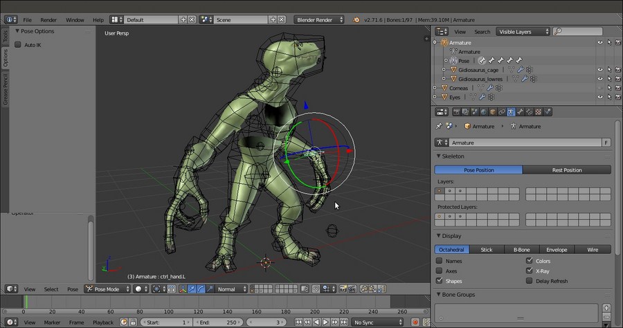
The Gidiosaurus model posed through the Mesh Deform modifier
Getting ready
First, we must prepare the deforming cage, which is a simplified low poly mesh totally enveloping the character's mesh; to do this, in our case, we can start from an already made object:
- Open the
Gidiosaurus_skinning_03.blendfile. - Click on the File | Append menu (or press Shift + F1), browse to the folder with all the project files, and click on the
Gidiosaurus_base_mesh_02.blendfile. Then, click on theObjectfolder and select the Gidiosaurus item. - Move the just-appended object to the first scene layer; then, go to the Outliner and rename it as Gidiosaurus_cage.
- This is the base mesh we built in the first chapter of this book, so go to the Object Modifier window and apply the Skin modifier; delete the Mirror modifier and disable the Subdivision Surface modifier visibility in the viewport by clicking on the eye icon button.
- Go in to Edit Mode and by pressing Ctrl +R, cut a median vertical edge-loop at the center of the mesh.
- Select the vertices of the missing half and delete them; then, select the median edge-loop and, with Pivot Point set to 3D Cursor (and the 3D Cursor located at the center of the scene), scale them to 0.000 along the global x axis.
- Assign a new Mirror modifier and enable the Clipping item.
Preparing the deforming cage
- Now, enable the scene layer with the Gidiosaurus mesh, select it, and temporarily disable the Armature modifier by clicking on the Display modifier in viewport button (the one with the eye icon).
- In the Outliner, click on the eye icon to hide the Armature.
- Reselect Gidiosaurus_cage, enter Edit Mode, and start to edit. Basically, the cage must be large enough to totally include the character's mesh.
- Select whole parts such as the head or a hand and scale the vertices on their normals (Alt + S) and move the vertices by hand.
- Where necessary, add edge-loops (Ctrl + R) to refine the cage's shape, but try to keep it as simple and low resolution as possible.
The cage mesh in Edit Mode
- Once we have confirmed that the Gidiosaurus mesh is totally contained in the cage, we can go out of Edit Mode.
Now that the deforming cage is made, we can go on with the skinning:
- Unhide the Armature and select it. Go in to Edit Mode, select the bones deforming the Armor (see the Parenting the Armature and Mesh using the Automatic Weights tool recipe in this chapter for this), and press Shift + W | Deform. Don't deselect anything because it will be useful later on to have the bones still selected, and go straight back to Object Mode.
- Now, hide the Gidiosaurus_lowres object; then, select the Gidiosaurus_cage object, Shift-select the Armature, and press Ctrl + P | With Automatic Weights.
- Select the sole Armature, go in to Edit Mode and press Shift + W | Deform, and then switch to Pose Mode.
- Reselect the cage and go to the Object Modifiers window; in the Armature modifier, enable the Preserve Volume item, but temporarily disable the visibility of the modifier in the viewport (eye icon button):
Parenting the deforming cage to the Armature
- Go to the Object window and click on the Maximum Draw Type button under the Display subpanel to select the Wire item. Unhide the Gidiosaurus_lowres object.
- Select the Gidiosaurus mesh and go in to Edit Mode. In the Vertex Groups subpanel under the Object Data window, create a new group and rename it as mdef; select all the vertices of the Gidiosaurus mesh except feet, fingers, and the head and assign them to the mdef vertex group:
The "mdef" vertex group
- Go to the Object Modifiers window; in the Armature modifier panel, click on the vertex group empty field at the bottom (name of Vertex Group which determines influence of modifier per point) to select the mdef vertex group and then click on the invert vertex group influence button to the left (the one with the two arrows pointing in opposite directions). Temporarily, disable the visibility of the modifier in the viewport (eye icon button).
- Assign a Mesh Deform modifier and move it upwards in the stack, before the Subdivision Surface modifier but after the Armature one.
- In the Object field of the Mesh Deform modifier, select the Gidiosaurus_cage item; in Vertex Group again, select the mdef vertex group, check the Dynamic item box, and then click on the Bind button.
- Save the file as
Gidiosaurus_mesh_deform.blend.
The Gidiosaurus_cage is a very simple mesh. Therefore, it is very easily skinned to the Armature (we didn't do it in our case, but obviously, when necessary, the automatic weights assigned by the parenting can be easily edited as in the Editing the Weight Groups using the Weight Paint tool recipe) and is therefore deforming, through the binding of the Mesh Deform modifier, the more subdivided Gidiosaurus mesh.
In fact, if everything went right, now we should have the Gidiosaurus body correctly deformed by the cage only for the vertices that belong to the mdef vertex group, while the Armature, which also deforms the cage, is still taking care of the vertices outside the group; to check this, just try to pose the rig and alternatively disable, in the Object Modifiers window, the viewport visibility of the Armature and Mesh Deform modifiers for the mesh.
Note that even we didn't apply the Mirror modifier to the cage object; the Mesh Deform modifier works correctly anyway, exactly like the Armature one.
The Gidiosaurus model posed through the Mesh Deform modifier
How to do it…
Now that the deforming cage is made, we can go on with the skinning:
- Unhide the Armature and select it. Go in to Edit Mode, select the bones deforming the Armor (see the Parenting the Armature and Mesh using the Automatic Weights tool recipe in this chapter for this), and press Shift + W | Deform. Don't deselect anything because it will be useful later on to have the bones still selected, and go straight back to Object Mode.
- Now, hide the Gidiosaurus_lowres object; then, select the Gidiosaurus_cage object, Shift-select the Armature, and press Ctrl + P | With Automatic Weights.
- Select the sole Armature, go in to Edit Mode and press Shift + W | Deform, and then switch to Pose Mode.
- Reselect the cage and go to the Object Modifiers window; in the Armature modifier, enable the Preserve Volume item, but temporarily disable the visibility of the modifier in the viewport (eye icon button):
Parenting the deforming cage to the Armature
- Go to the Object window and click on the Maximum Draw Type button under the Display subpanel to select the Wire item. Unhide the Gidiosaurus_lowres object.
- Select the Gidiosaurus mesh and go in to Edit Mode. In the Vertex Groups subpanel under the Object Data window, create a new group and rename it as mdef; select all the vertices of the Gidiosaurus mesh except feet, fingers, and the head and assign them to the mdef vertex group:
The "mdef" vertex group
- Go to the Object Modifiers window; in the Armature modifier panel, click on the vertex group empty field at the bottom (name of Vertex Group which determines influence of modifier per point) to select the mdef vertex group and then click on the invert vertex group influence button to the left (the one with the two arrows pointing in opposite directions). Temporarily, disable the visibility of the modifier in the viewport (eye icon button).
- Assign a Mesh Deform modifier and move it upwards in the stack, before the Subdivision Surface modifier but after the Armature one.
- In the Object field of the Mesh Deform modifier, select the Gidiosaurus_cage item; in Vertex Group again, select the mdef vertex group, check the Dynamic item box, and then click on the Bind button.
- Save the file as
Gidiosaurus_mesh_deform.blend.
The Gidiosaurus_cage is a very simple mesh. Therefore, it is very easily skinned to the Armature (we didn't do it in our case, but obviously, when necessary, the automatic weights assigned by the parenting can be easily edited as in the Editing the Weight Groups using the Weight Paint tool recipe) and is therefore deforming, through the binding of the Mesh Deform modifier, the more subdivided Gidiosaurus mesh.
In fact, if everything went right, now we should have the Gidiosaurus body correctly deformed by the cage only for the vertices that belong to the mdef vertex group, while the Armature, which also deforms the cage, is still taking care of the vertices outside the group; to check this, just try to pose the rig and alternatively disable, in the Object Modifiers window, the viewport visibility of the Armature and Mesh Deform modifiers for the mesh.
Note that even we didn't apply the Mirror modifier to the cage object; the Mesh Deform modifier works correctly anyway, exactly like the Armature one.
The Gidiosaurus model posed through the Mesh Deform modifier
How it works…
The Gidiosaurus_cage is a very simple mesh. Therefore, it is very easily skinned to the Armature (we didn't do it in our case, but obviously, when necessary, the automatic weights assigned by the parenting can be easily edited as in the Editing the Weight Groups using the Weight Paint tool recipe) and is therefore deforming, through the binding of the Mesh Deform modifier, the more subdivided Gidiosaurus mesh.
In fact, if everything went right, now we should have the Gidiosaurus body correctly deformed by the cage only for the vertices that belong to the mdef vertex group, while the Armature, which also deforms the cage, is still taking care of the vertices outside the group; to check this, just try to pose the rig and alternatively disable, in the Object Modifiers window, the viewport visibility of the Armature and Mesh Deform modifiers for the mesh.
Note that even we didn't apply the Mirror modifier to the cage object; the Mesh Deform modifier works correctly anyway, exactly like the Armature one.
The Gidiosaurus model posed through the Mesh Deform modifier
One of the last modifiers introduced in Blender, the Laplacian Deform modifier shouldn't actually be considered as an effective tool to rig a character, but more as a tool to modify, change, or refine a default pose. Anyway, if set and used smartly it can often give interesting results, so it has been included in this chapter as well.
First, let's prepare the scene:
- Open the
Gidiosaurus_rig_from_scratch_01.blendfile. - Select and then delete the Armature in Object Mode; then. select the Gidiosaurus mesh and delete the Armature modifier too in the Object Modifiers window.
- In the Outliner, hide the Eyes object.
- Press the Z key to go in the Wireframe viewport shading mode.
Now let's go with the Laplacian modifier setup:
- With the Gidiosaurus mesh still in Edit Mode, select all the vertices of the hands, feet, hip, head, plus the boundary edge-loops where the mesh is missing (look at the following screenshot).
- Go to the Vertex Groups subpanel and create a new group named as you wish; I named it lapldef. Assign the selected vertices with a Weight value of 1.000:

The "lapldef" vertex group
- Now, box-deselect all the vertices, except the head ones; press Ctrl + H and in the Hooks pop-up menu, select the Hook to New Object item:

The Hooks menu
- Click on the Select button under the Vertex Groups subpanel to the right of the screen and then deselect all the vertices, except the right hand ones. Again, press Ctrl + H and in the Hooks pop-up menu, select the Hook to New Object item.
- Click on the Select button again, deselect all the vertices, except the left hand ones, and repeat the procedure:

The Hook assigned to the left hand vertices
- Repeat the procedure separately for the left and the right feet and then go out of Edit Mode.
- In the Outliner, rename the Empties (the Hooks) respectively as Empty_head, Empty_hand.L and .R, and Empty_foot.L and .R.

The Hooks assigned to the mesh's vertices
- Select the Gidiosaurus mesh and go to the Object Modifiers window. Collapse all the five Hook modifiers for better visibility and assign a Laplacian Deform modifier; move it upwards in the stack, just before the Subdivision Surface modifier (but always after the Hook modifiers). Click on the Anchors Vertex Group to select the lapldef vertex group and then click on the Bind button.
- For better visibility, select each Hook and in the Object Data window, set the size to 0.40.
- Enable the 3D manipulator widget in the 3D view toolbar (or press Ctrl + Spacebar), Shift-click on the Translate and Rotate buttons, and set Transform Orientation to Normal.
- Select the Hooks and start to move and rotate them using the 3D manipulator widget, to pose the Gidiosaurus mesh:

The Gidiosaurus mesh posed through the Hooks and the Laplacian Deform modifier
- Save the file as
Gidiosaurus_laplacian.blend.
Remember that because they don't work through joints, the Laplacian Deform modifier and the Hooks don't give a realistic deformation and should be used more to tweak a character pose only inside a limited range. Building a more complex rig, also with Hooks at the elbows and knees, is possible but probably more useful for other types of unreal characters' shapes.
It should also be remembered that the Hooks, once moved out of their location, can't be simply moved back to their original position by the Alt + G shortcut because this command would set them at their original 0, 0, 0 location. Instead, any rotation can be easily removed by the Alt + R shortcut.
In any case, the Ctrl + Z (Undo) shortcut can be used, but first check the number of Steps set in the User Preferences panel under the Global Undo item (there are only 32 by default).
Getting ready
First, let's prepare the scene:
- Open the
Gidiosaurus_rig_from_scratch_01.blendfile. - Select and then delete the Armature in Object Mode; then. select the Gidiosaurus mesh and delete the Armature modifier too in the Object Modifiers window.
- In the Outliner, hide the Eyes object.
- Press the Z key to go in the Wireframe viewport shading mode.
Now let's go with the Laplacian modifier setup:
- With the Gidiosaurus mesh still in Edit Mode, select all the vertices of the hands, feet, hip, head, plus the boundary edge-loops where the mesh is missing (look at the following screenshot).
- Go to the Vertex Groups subpanel and create a new group named as you wish; I named it lapldef. Assign the selected vertices with a Weight value of 1.000:
The "lapldef" vertex group
- Now, box-deselect all the vertices, except the head ones; press Ctrl + H and in the Hooks pop-up menu, select the Hook to New Object item:
The Hooks menu
- Click on the Select button under the Vertex Groups subpanel to the right of the screen and then deselect all the vertices, except the right hand ones. Again, press Ctrl + H and in the Hooks pop-up menu, select the Hook to New Object item.
- Click on the Select button again, deselect all the vertices, except the left hand ones, and repeat the procedure:
The Hook assigned to the left hand vertices
- Repeat the procedure separately for the left and the right feet and then go out of Edit Mode.
- In the Outliner, rename the Empties (the Hooks) respectively as Empty_head, Empty_hand.L and .R, and Empty_foot.L and .R.
The Hooks assigned to the mesh's vertices
- Select the Gidiosaurus mesh and go to the Object Modifiers window. Collapse all the five Hook modifiers for better visibility and assign a Laplacian Deform modifier; move it upwards in the stack, just before the Subdivision Surface modifier (but always after the Hook modifiers). Click on the Anchors Vertex Group to select the lapldef vertex group and then click on the Bind button.
- For better visibility, select each Hook and in the Object Data window, set the size to 0.40.
- Enable the 3D manipulator widget in the 3D view toolbar (or press Ctrl + Spacebar), Shift-click on the Translate and Rotate buttons, and set Transform Orientation to Normal.
- Select the Hooks and start to move and rotate them using the 3D manipulator widget, to pose the Gidiosaurus mesh:
The Gidiosaurus mesh posed through the Hooks and the Laplacian Deform modifier
- Save the file as
Gidiosaurus_laplacian.blend.
Remember that because they don't work through joints, the Laplacian Deform modifier and the Hooks don't give a realistic deformation and should be used more to tweak a character pose only inside a limited range. Building a more complex rig, also with Hooks at the elbows and knees, is possible but probably more useful for other types of unreal characters' shapes.
It should also be remembered that the Hooks, once moved out of their location, can't be simply moved back to their original position by the Alt + G shortcut because this command would set them at their original 0, 0, 0 location. Instead, any rotation can be easily removed by the Alt + R shortcut.
In any case, the Ctrl + Z (Undo) shortcut can be used, but first check the number of Steps set in the User Preferences panel under the Global Undo item (there are only 32 by default).
How to do it…
Now let's go with the Laplacian modifier setup:
- With the Gidiosaurus mesh still in Edit Mode, select all the vertices of the hands, feet, hip, head, plus the boundary edge-loops where the mesh is missing (look at the following screenshot).
- Go to the Vertex Groups subpanel and create a new group named as you wish; I named it lapldef. Assign the selected vertices with a Weight value of 1.000:
The "lapldef" vertex group
- Now, box-deselect all the vertices, except the head ones; press Ctrl + H and in the Hooks pop-up menu, select the Hook to New Object item:
The Hooks menu
- Click on the Select button under the Vertex Groups subpanel to the right of the screen and then deselect all the vertices, except the right hand ones. Again, press Ctrl + H and in the Hooks pop-up menu, select the Hook to New Object item.
- Click on the Select button again, deselect all the vertices, except the left hand ones, and repeat the procedure:
The Hook assigned to the left hand vertices
- Repeat the procedure separately for the left and the right feet and then go out of Edit Mode.
- In the Outliner, rename the Empties (the Hooks) respectively as Empty_head, Empty_hand.L and .R, and Empty_foot.L and .R.
The Hooks assigned to the mesh's vertices
- Select the Gidiosaurus mesh and go to the Object Modifiers window. Collapse all the five Hook modifiers for better visibility and assign a Laplacian Deform modifier; move it upwards in the stack, just before the Subdivision Surface modifier (but always after the Hook modifiers). Click on the Anchors Vertex Group to select the lapldef vertex group and then click on the Bind button.
- For better visibility, select each Hook and in the Object Data window, set the size to 0.40.
- Enable the 3D manipulator widget in the 3D view toolbar (or press Ctrl + Spacebar), Shift-click on the Translate and Rotate buttons, and set Transform Orientation to Normal.
- Select the Hooks and start to move and rotate them using the 3D manipulator widget, to pose the Gidiosaurus mesh:
The Gidiosaurus mesh posed through the Hooks and the Laplacian Deform modifier
- Save the file as
Gidiosaurus_laplacian.blend.
Remember that because they don't work through joints, the Laplacian Deform modifier and the Hooks don't give a realistic deformation and should be used more to tweak a character pose only inside a limited range. Building a more complex rig, also with Hooks at the elbows and knees, is possible but probably more useful for other types of unreal characters' shapes.
It should also be remembered that the Hooks, once moved out of their location, can't be simply moved back to their original position by the Alt + G shortcut because this command would set them at their original 0, 0, 0 location. Instead, any rotation can be easily removed by the Alt + R shortcut.
In any case, the Ctrl + Z (Undo) shortcut can be used, but first check the number of Steps set in the User Preferences panel under the Global Undo item (there are only 32 by default).
How it works…
Remember that because they don't work through joints, the Laplacian Deform modifier and the Hooks don't give a realistic deformation and should be used more to tweak a character pose only inside a limited range. Building a more complex rig, also with Hooks at the elbows and knees, is possible but probably more useful for other types of unreal characters' shapes.
It should also be remembered that the Hooks, once moved out of their location, can't be simply moved back to their original position by the Alt + G shortcut because this command would set them at their original 0, 0, 0 location. Instead, any rotation can be easily removed by the Alt + R shortcut.
In any case, the Ctrl + Z (Undo) shortcut can be used, but first check the number of Steps set in the User Preferences panel under the Global Undo item (there are only 32 by default).
In this chapter, we will cover the following recipes:
- Creating shape keys
- Assigning drivers to the shape keys
- Setting movement limit constraints
- Transferring the eyeball rotation to the eyelids
- Detailing the Armor by using the Curve from Mesh tool
In this chapter, we'll see how to create and add shape keys (the Blender term for morphing) to the model, to create facial expressions for the Gidiosaurus and to add shape modifications in a non-destructive way to the model.
Then, we'll see how to set a limit to the Armature bones' rotation using constraints and how to slightly transfer a portion of the rotation movement of the eyeballs to the covering eyelids.
Last, we'll add some detail to the Armor by quickly adding rivets through a simple and effective technique.
In this recipe, we'll set the shape keys to create (even if limited) facial expressions and to fake the stretching and the contracting effect of the character's arm muscles, and we'll add some more shape keys to fix issues in the character's shape.
First, let's prepare a bit the scene and the model:
- Start Blender and load the
Gidiosaurus_skinning_rigify.blendfile, which is the same as theGidiosaurus_skinning_03.blendfile but with the rig created by the Rigify add-on (and later edited to add the other bones exactly as explained in the last chapter's recipes). - In the Outliner, click on the respective eye icons to hide the Armor, Eyes, and Tiers_simplified objects and the Armature, whose name in this case is rig.
- Select the Gidiosaurus_lowres object and press the 1 key on the numpad to go into the Front view.
- Press Z to go into the Wireframe viewport shading mode and the 5 key on the numpad to switch to the Ortho view if it is not already.
- Enter Edit Mode and box-select the left half of the mesh vertices (including the middle vertical edge-loop) and in the Vertex Groups subpanel under the Object Data window, create a new vertex group; rename it left and assign the selected vertices a weight of 1.000.
- Deselect everything and repeat this process for the right half of the mesh's vertices to create the right vertex group:

Assigning the mesh's right side vertices to the "right" vertex group
- Save the file as
Gidiosaurus_shapekeys.blend.
Let's start now by creating the facial expressions shape keys:
- Exit Edit Mode and expand the Shape Keys subpanel under the Object Data window; click on the + icon button to the top left to create the Basis shape key (that mustn't be edited), then click once more to create the Key 1 shape key (that is, instead, the one to be edited):

Creating the Basis and the first shape key
- Be sure that the X Mirror item in the Mesh Options tab under the Tool Shelf is activated and click on the PET (Proportional Editing Tool) button in the 3D viewport toolbar (or activate it by pressing the O key).
- Zoom to the Gidiosaurus head and again in Edit Mode, select some of the vertices at the center of the snout area, as indicated in the following screenshot:

Selecting the vertices
- Move them upwards and towards the eye, set the amount for the PET smoothing by scrolling the mouse wheel:

Moving the selected vertices slightly backwards and upwards
Note that we selected two faces instead of the folder edges, because the muscular scrunching involves both movement of the skin and a slight folding of the skin as well; the middle edge does not move as much as the selected faces due to PET falloff, hence creating a very slight scrunch and a more naturalistic skin sliding.
- If necessary, adjust the position of the single vertices, maybe also disabling the PET.
- Go to the Shape Keys subpanel and rename the Key 1 shape key as grin.
- Click on the Apply shape key in edit mode button located right above the Value slider to enable it; go into the Front view and by moving the Value slider from 0.000 to 1.000 and back, check for the correct working of the shape key on both the sides of the character:

Checking how the "grin" shape key works
- Go out of Edit Mode and just to have better visibility of the shape key modifications, go to the Object window to enable the Wire item in the Display subpanel.
- Go back to the Object Data window and click on the button that has an icon of a downward pointing arrow (Shape keys specials); from the pop-up menu select the New Shape from Mix item: this adds a new shape key made by the sum of all the active shape keys. In this case, it is just a perfect copy of the sole grin shape key (the Basis shape key is, well, just the base starting position of the vertices in the mesh). Rename the two shape keys as grin.L and grin.R.

Copying the "grin" shape key to a new one
- Click on the grin.L shape key, set the Value slider back to 0.000, and then click on the Vertex weight group slot, the one under the Blend item and above the Basis one, and select the left vertex group.
- Repeat for the grin.R shape key by selecting the right vertex group, and then once again set the Value slider to 1.000 and ensure it works correctly.
Each shape key now works only on the respective side, according to the selected vertex group:

The two "grin" shape keys for the right and the left sides
This was for the grin expression; now we need to add at least two or three more kinds of shape keys, namely: two for the eyebrows (up and down) and one for the nostrils, multiplied for each side.
This means six more shape keys in total, but as you have seen, the procedure is quite quick and simple.
- Set the Value slider for the grin.L and grin.R shape keys back to 0.000 and click on the + icon button to add a new shape key.
- Rename it eyebrow_up.L and enter Edit Mode; grab some vertices on the left eyebrow and, still with the PET activated, move them upward; you can use the mouse wheel to set the influence of the PET:

Moving the eyebrow upward
- Repeat the steps from 9 to 11 to create the eyebrow_up.R shape key.
- Repeat the steps from 3 to 11 to create the eyebrow_down.L and eyebrow_down.R shape keys:

Moving the eyebrow downward
- Finally repeat step 3 to step 11, this time selecting the vertices around the nostrils and scaling them to be bigger, creating the snare.L and snare.R shape keys:

The nostril flaring
Note that, when naming the shape key for the enlargement of the nostrils, I erroneously wrote snare; it should have been something like snarl or flaring, but in the end it's just a naming convention and therefore, this little mistake doesn't pose a real problem.
We are done with the facial expressions; now let's add one more shape key to enhance some of the body features of the Gidiosaurus a bit; these are not meant to be animated during the animation, but are simply a way to apply non-destructive modifications to the model.
- Add a new shape key and rename it prop (for proportions).
- In Edit Mode, select the vertices of the left foot, excluding the feet talons, and press Alt + S to scale them on their normals; if you are using the PET, just be sure to be in the Connected mode (so that the PET has influence only on the vertices connected to the selected ones, otherwise the unselected feet talon vertices will also be modified):

Modifying the feet proportions
- Disable the PET and adjust the transition between the scaled vertices and the surrounding ones, the area between the two toes, and so on.
- If you wish, you may also make additional modifications; in my case, besides the bigger feet, I simply enhanced the knuckles on the hands and at the fingers' joints. Also, I tweaked the rim shape of the upper and bottom borders of the mandibles a bit:

Enhancing some of the character's features
- When you are done, set the Value slider of the prop shape key to 1.000.
Now, let's add a couple of shape keys to mimic the movement of the main muscles of the arms, specifically of the biceps and of the triceps muscles:
- Add a new shape key, then go to the Gidiosaurus mesh; select some of the vertices in the middle area of the bicep muscle and after enabling the PET again, move them forward and also scale them to be bigger, to make the muscle grow:

Making the bicep muscle grow
- Rename the shape key bicep.L, and then repeat the steps from 9 to 11 to create the bicep.R shape key.
- Add a new shape key and repeat everything by selecting vertices on the back of the arm, in the triceps area, to create the triceps.L and the triceps.R shape keys.

Making the triceps muscle grow
- Leave the values of these last four shape keys as 0.000 and exit Edit Mode.
More shape keys could be added to simulate a complete muscle system, but in our case we stop here with the Gidiosaurus mesh; now let's concentrate on the Armor.
- Go to the Outliner and unhide both Armor and rig.
- Select the rig and then press N to call the Properties 3D view sidepanel; scroll to the bottom and first go to the Rig Main Properties subpanel to set both the slider for FK/IK (hand.ik.L) and (hand.ik.R) to 1.000, then go down to the Rig Layers subpanel and deselect everything except for the Arm.L (IK) and Arm.R (IK) buttons.
- Go to the 3D viewport and select the hand.ik.L and hand.ik.R handle bones, go into the Side view and move them towards the upper back.

Moving the arm control bones backward using the Inverse Kinematics
- Now press Ctrl + numpad 1 to go in Back view and move the hand.ik.L bone to 0.200 along the global x axis; select the hand.ik.R bone and move it to -0.200:

Adjusting the lateral position of the arms
- Now select the Armor object and add the Basis shape key in the Shape Keys subpanel under the Object Data window, and then add Key 1.
- Enter Edit Mode and press the slash key (/) on the numpad to go in Local view; this way only the selected objects are visible in the viewport, in our case only the Armor. Using the Proportional Editing mode, start to enlarge the back section of the opening for the arms, adjust the position of the surrounding vertices as required, and also raise the back vertices of the spaulders a bit, to avoid interpenetration with the borders of the chest plate and the shoulder as well.
- Press the numpad slash (/) key again to go out of the Local view and check for the correction with the Gidiosaurus mesh:

Editing the position of the Armor vertices for a new shape key
- When you are done, just exit Edit Mode and set the Value slider of the Key 1 shape key for the Armor to 1.000:

The shape key working as a fix for the Armor
- Rename the Key 1 shape key as Armor_fix and save the file.
Although technically there are no differences, we could say that we created three different types of shape key:
- One type to fix shape errors or make improvements in the mesh, for example, with the prop and the Armor_fix shape keys
- The second type to modify the mesh only at certain established moments during the animation process, in our case just to animate facial expressions
- The third type to simulate muscle movements in the character
Shape keys work in linear space; that means that it's not possible to make vertices rotate around a pivot through a shape key, but only to move them from point A to point B. That's why we didn't use shape keys for stuff like the eyelid movements, for example, or the opening/closing of the jaw, but only for actions including muscles sliding above the bones such as the eyebrows, the grin, and the nostrils, as well as the bicep/triceps movements.
Thanks to shape keys, we also made last minute modifications and improvements to the Gidiosaurus mesh and to the Armor; being included inside a shape key, all these modifications are non-destructive and can be turned on or off at will, or their influence can be set at an intermediate strength value.
When modifying a mesh using a shape key, be careful not to change too much of the mutual proportions of articulated parts of a to-be-deformed mesh; for example, it's usually problematic to scale a whole part such as the hands or the head of a character, both smaller or bigger, unless you also scale the corresponding bones of the rig and the joints' position accordingly as well.
Beyond a certain threshold, the bones of the fingers, or of the eyes and jaw, start to be out of register compared to the respective mesh's edge-loops and you'll have to fix this by re-positioning the joints of the Armature's bones (just in case, remember: always do this in Edit Mode).
In our example, with the prop shape key, we just restricted ourselves to enhance the hands' knuckles and to make stronger feet by simply making the vertices' positions grow in the direction of their normals.
Getting ready
First, let's prepare a bit the scene and the model:
- Start Blender and load the
Gidiosaurus_skinning_rigify.blendfile, which is the same as theGidiosaurus_skinning_03.blendfile but with the rig created by the Rigify add-on (and later edited to add the other bones exactly as explained in the last chapter's recipes). - In the Outliner, click on the respective eye icons to hide the Armor, Eyes, and Tiers_simplified objects and the Armature, whose name in this case is rig.
- Select the Gidiosaurus_lowres object and press the 1 key on the numpad to go into the Front view.
- Press Z to go into the Wireframe viewport shading mode and the 5 key on the numpad to switch to the Ortho view if it is not already.
- Enter Edit Mode and box-select the left half of the mesh vertices (including the middle vertical edge-loop) and in the Vertex Groups subpanel under the Object Data window, create a new vertex group; rename it left and assign the selected vertices a weight of 1.000.
- Deselect everything and repeat this process for the right half of the mesh's vertices to create the right vertex group:
Assigning the mesh's right side vertices to the "right" vertex group
- Save the file as
Gidiosaurus_shapekeys.blend.
Let's start now by creating the facial expressions shape keys:
- Exit Edit Mode and expand the Shape Keys subpanel under the Object Data window; click on the + icon button to the top left to create the Basis shape key (that mustn't be edited), then click once more to create the Key 1 shape key (that is, instead, the one to be edited):
Creating the Basis and the first shape key
- Be sure that the X Mirror item in the Mesh Options tab under the Tool Shelf is activated and click on the PET (Proportional Editing Tool) button in the 3D viewport toolbar (or activate it by pressing the O key).
- Zoom to the Gidiosaurus head and again in Edit Mode, select some of the vertices at the center of the snout area, as indicated in the following screenshot:
Selecting the vertices
- Move them upwards and towards the eye, set the amount for the PET smoothing by scrolling the mouse wheel:
Moving the selected vertices slightly backwards and upwards
Note that we selected two faces instead of the folder edges, because the muscular scrunching involves both movement of the skin and a slight folding of the skin as well; the middle edge does not move as much as the selected faces due to PET falloff, hence creating a very slight scrunch and a more naturalistic skin sliding.
- If necessary, adjust the position of the single vertices, maybe also disabling the PET.
- Go to the Shape Keys subpanel and rename the Key 1 shape key as grin.
- Click on the Apply shape key in edit mode button located right above the Value slider to enable it; go into the Front view and by moving the Value slider from 0.000 to 1.000 and back, check for the correct working of the shape key on both the sides of the character:
Checking how the "grin" shape key works
- Go out of Edit Mode and just to have better visibility of the shape key modifications, go to the Object window to enable the Wire item in the Display subpanel.
- Go back to the Object Data window and click on the button that has an icon of a downward pointing arrow (Shape keys specials); from the pop-up menu select the New Shape from Mix item: this adds a new shape key made by the sum of all the active shape keys. In this case, it is just a perfect copy of the sole grin shape key (the Basis shape key is, well, just the base starting position of the vertices in the mesh). Rename the two shape keys as grin.L and grin.R.
Copying the "grin" shape key to a new one
- Click on the grin.L shape key, set the Value slider back to 0.000, and then click on the Vertex weight group slot, the one under the Blend item and above the Basis one, and select the left vertex group.
- Repeat for the grin.R shape key by selecting the right vertex group, and then once again set the Value slider to 1.000 and ensure it works correctly.
Each shape key now works only on the respective side, according to the selected vertex group:
The two "grin" shape keys for the right and the left sides
This was for the grin expression; now we need to add at least two or three more kinds of shape keys, namely: two for the eyebrows (up and down) and one for the nostrils, multiplied for each side.
This means six more shape keys in total, but as you have seen, the procedure is quite quick and simple.
- Set the Value slider for the grin.L and grin.R shape keys back to 0.000 and click on the + icon button to add a new shape key.
- Rename it eyebrow_up.L and enter Edit Mode; grab some vertices on the left eyebrow and, still with the PET activated, move them upward; you can use the mouse wheel to set the influence of the PET:
Moving the eyebrow upward
- Repeat the steps from 9 to 11 to create the eyebrow_up.R shape key.
- Repeat the steps from 3 to 11 to create the eyebrow_down.L and eyebrow_down.R shape keys:
Moving the eyebrow downward
- Finally repeat step 3 to step 11, this time selecting the vertices around the nostrils and scaling them to be bigger, creating the snare.L and snare.R shape keys:
The nostril flaring
Note that, when naming the shape key for the enlargement of the nostrils, I erroneously wrote snare; it should have been something like snarl or flaring, but in the end it's just a naming convention and therefore, this little mistake doesn't pose a real problem.
We are done with the facial expressions; now let's add one more shape key to enhance some of the body features of the Gidiosaurus a bit; these are not meant to be animated during the animation, but are simply a way to apply non-destructive modifications to the model.
- Add a new shape key and rename it prop (for proportions).
- In Edit Mode, select the vertices of the left foot, excluding the feet talons, and press Alt + S to scale them on their normals; if you are using the PET, just be sure to be in the Connected mode (so that the PET has influence only on the vertices connected to the selected ones, otherwise the unselected feet talon vertices will also be modified):
Modifying the feet proportions
- Disable the PET and adjust the transition between the scaled vertices and the surrounding ones, the area between the two toes, and so on.
- If you wish, you may also make additional modifications; in my case, besides the bigger feet, I simply enhanced the knuckles on the hands and at the fingers' joints. Also, I tweaked the rim shape of the upper and bottom borders of the mandibles a bit:
Enhancing some of the character's features
- When you are done, set the Value slider of the prop shape key to 1.000.
Now, let's add a couple of shape keys to mimic the movement of the main muscles of the arms, specifically of the biceps and of the triceps muscles:
- Add a new shape key, then go to the Gidiosaurus mesh; select some of the vertices in the middle area of the bicep muscle and after enabling the PET again, move them forward and also scale them to be bigger, to make the muscle grow:
Making the bicep muscle grow
- Rename the shape key bicep.L, and then repeat the steps from 9 to 11 to create the bicep.R shape key.
- Add a new shape key and repeat everything by selecting vertices on the back of the arm, in the triceps area, to create the triceps.L and the triceps.R shape keys.
Making the triceps muscle grow
- Leave the values of these last four shape keys as 0.000 and exit Edit Mode.
More shape keys could be added to simulate a complete muscle system, but in our case we stop here with the Gidiosaurus mesh; now let's concentrate on the Armor.
- Go to the Outliner and unhide both Armor and rig.
- Select the rig and then press N to call the Properties 3D view sidepanel; scroll to the bottom and first go to the Rig Main Properties subpanel to set both the slider for FK/IK (hand.ik.L) and (hand.ik.R) to 1.000, then go down to the Rig Layers subpanel and deselect everything except for the Arm.L (IK) and Arm.R (IK) buttons.
- Go to the 3D viewport and select the hand.ik.L and hand.ik.R handle bones, go into the Side view and move them towards the upper back.
Moving the arm control bones backward using the Inverse Kinematics
- Now press Ctrl + numpad 1 to go in Back view and move the hand.ik.L bone to 0.200 along the global x axis; select the hand.ik.R bone and move it to -0.200:
Adjusting the lateral position of the arms
- Now select the Armor object and add the Basis shape key in the Shape Keys subpanel under the Object Data window, and then add Key 1.
- Enter Edit Mode and press the slash key (/) on the numpad to go in Local view; this way only the selected objects are visible in the viewport, in our case only the Armor. Using the Proportional Editing mode, start to enlarge the back section of the opening for the arms, adjust the position of the surrounding vertices as required, and also raise the back vertices of the spaulders a bit, to avoid interpenetration with the borders of the chest plate and the shoulder as well.
- Press the numpad slash (/) key again to go out of the Local view and check for the correction with the Gidiosaurus mesh:
Editing the position of the Armor vertices for a new shape key
- When you are done, just exit Edit Mode and set the Value slider of the Key 1 shape key for the Armor to 1.000:
The shape key working as a fix for the Armor
- Rename the Key 1 shape key as Armor_fix and save the file.
Although technically there are no differences, we could say that we created three different types of shape key:
- One type to fix shape errors or make improvements in the mesh, for example, with the prop and the Armor_fix shape keys
- The second type to modify the mesh only at certain established moments during the animation process, in our case just to animate facial expressions
- The third type to simulate muscle movements in the character
Shape keys work in linear space; that means that it's not possible to make vertices rotate around a pivot through a shape key, but only to move them from point A to point B. That's why we didn't use shape keys for stuff like the eyelid movements, for example, or the opening/closing of the jaw, but only for actions including muscles sliding above the bones such as the eyebrows, the grin, and the nostrils, as well as the bicep/triceps movements.
Thanks to shape keys, we also made last minute modifications and improvements to the Gidiosaurus mesh and to the Armor; being included inside a shape key, all these modifications are non-destructive and can be turned on or off at will, or their influence can be set at an intermediate strength value.
When modifying a mesh using a shape key, be careful not to change too much of the mutual proportions of articulated parts of a to-be-deformed mesh; for example, it's usually problematic to scale a whole part such as the hands or the head of a character, both smaller or bigger, unless you also scale the corresponding bones of the rig and the joints' position accordingly as well.
Beyond a certain threshold, the bones of the fingers, or of the eyes and jaw, start to be out of register compared to the respective mesh's edge-loops and you'll have to fix this by re-positioning the joints of the Armature's bones (just in case, remember: always do this in Edit Mode).
In our example, with the prop shape key, we just restricted ourselves to enhance the hands' knuckles and to make stronger feet by simply making the vertices' positions grow in the direction of their normals.
How to do it…
Let's start now by creating the facial expressions shape keys:
- Exit Edit Mode and expand the Shape Keys subpanel under the Object Data window; click on the + icon button to the top left to create the Basis shape key (that mustn't be edited), then click once more to create the Key 1 shape key (that is, instead, the one to be edited):
Creating the Basis and the first shape key
- Be sure that the X Mirror item in the Mesh Options tab under the Tool Shelf is activated and click on the PET (Proportional Editing Tool) button in the 3D viewport toolbar (or activate it by pressing the O key).
- Zoom to the Gidiosaurus head and again in Edit Mode, select some of the vertices at the center of the snout area, as indicated in the following screenshot:
Selecting the vertices
- Move them upwards and towards the eye, set the amount for the PET smoothing by scrolling the mouse wheel:
Moving the selected vertices slightly backwards and upwards
Note that we selected two faces instead of the folder edges, because the muscular scrunching involves both movement of the skin and a slight folding of the skin as well; the middle edge does not move as much as the selected faces due to PET falloff, hence creating a very slight scrunch and a more naturalistic skin sliding.
- If necessary, adjust the position of the single vertices, maybe also disabling the PET.
- Go to the Shape Keys subpanel and rename the Key 1 shape key as grin.
- Click on the Apply shape key in edit mode button located right above the Value slider to enable it; go into the Front view and by moving the Value slider from 0.000 to 1.000 and back, check for the correct working of the shape key on both the sides of the character:
Checking how the "grin" shape key works
- Go out of Edit Mode and just to have better visibility of the shape key modifications, go to the Object window to enable the Wire item in the Display subpanel.
- Go back to the Object Data window and click on the button that has an icon of a downward pointing arrow (Shape keys specials); from the pop-up menu select the New Shape from Mix item: this adds a new shape key made by the sum of all the active shape keys. In this case, it is just a perfect copy of the sole grin shape key (the Basis shape key is, well, just the base starting position of the vertices in the mesh). Rename the two shape keys as grin.L and grin.R.
Copying the "grin" shape key to a new one
- Click on the grin.L shape key, set the Value slider back to 0.000, and then click on the Vertex weight group slot, the one under the Blend item and above the Basis one, and select the left vertex group.
- Repeat for the grin.R shape key by selecting the right vertex group, and then once again set the Value slider to 1.000 and ensure it works correctly.
Each shape key now works only on the respective side, according to the selected vertex group:
The two "grin" shape keys for the right and the left sides
This was for the grin expression; now we need to add at least two or three more kinds of shape keys, namely: two for the eyebrows (up and down) and one for the nostrils, multiplied for each side.
This means six more shape keys in total, but as you have seen, the procedure is quite quick and simple.
- Set the Value slider for the grin.L and grin.R shape keys back to 0.000 and click on the + icon button to add a new shape key.
- Rename it eyebrow_up.L and enter Edit Mode; grab some vertices on the left eyebrow and, still with the PET activated, move them upward; you can use the mouse wheel to set the influence of the PET:
Moving the eyebrow upward
- Repeat the steps from 9 to 11 to create the eyebrow_up.R shape key.
- Repeat the steps from 3 to 11 to create the eyebrow_down.L and eyebrow_down.R shape keys:
Moving the eyebrow downward
- Finally repeat step 3 to step 11, this time selecting the vertices around the nostrils and scaling them to be bigger, creating the snare.L and snare.R shape keys:
The nostril flaring
Note that, when naming the shape key for the enlargement of the nostrils, I erroneously wrote snare; it should have been something like snarl or flaring, but in the end it's just a naming convention and therefore, this little mistake doesn't pose a real problem.
We are done with the facial expressions; now let's add one more shape key to enhance some of the body features of the Gidiosaurus a bit; these are not meant to be animated during the animation, but are simply a way to apply non-destructive modifications to the model.
- Add a new shape key and rename it prop (for proportions).
- In Edit Mode, select the vertices of the left foot, excluding the feet talons, and press Alt + S to scale them on their normals; if you are using the PET, just be sure to be in the Connected mode (so that the PET has influence only on the vertices connected to the selected ones, otherwise the unselected feet talon vertices will also be modified):
Modifying the feet proportions
- Disable the PET and adjust the transition between the scaled vertices and the surrounding ones, the area between the two toes, and so on.
- If you wish, you may also make additional modifications; in my case, besides the bigger feet, I simply enhanced the knuckles on the hands and at the fingers' joints. Also, I tweaked the rim shape of the upper and bottom borders of the mandibles a bit:
Enhancing some of the character's features
- When you are done, set the Value slider of the prop shape key to 1.000.
Now, let's add a couple of shape keys to mimic the movement of the main muscles of the arms, specifically of the biceps and of the triceps muscles:
- Add a new shape key, then go to the Gidiosaurus mesh; select some of the vertices in the middle area of the bicep muscle and after enabling the PET again, move them forward and also scale them to be bigger, to make the muscle grow:
Making the bicep muscle grow
- Rename the shape key bicep.L, and then repeat the steps from 9 to 11 to create the bicep.R shape key.
- Add a new shape key and repeat everything by selecting vertices on the back of the arm, in the triceps area, to create the triceps.L and the triceps.R shape keys.
Making the triceps muscle grow
- Leave the values of these last four shape keys as 0.000 and exit Edit Mode.
More shape keys could be added to simulate a complete muscle system, but in our case we stop here with the Gidiosaurus mesh; now let's concentrate on the Armor.
- Go to the Outliner and unhide both Armor and rig.
- Select the rig and then press N to call the Properties 3D view sidepanel; scroll to the bottom and first go to the Rig Main Properties subpanel to set both the slider for FK/IK (hand.ik.L) and (hand.ik.R) to 1.000, then go down to the Rig Layers subpanel and deselect everything except for the Arm.L (IK) and Arm.R (IK) buttons.
- Go to the 3D viewport and select the hand.ik.L and hand.ik.R handle bones, go into the Side view and move them towards the upper back.
Moving the arm control bones backward using the Inverse Kinematics
- Now press Ctrl + numpad 1 to go in Back view and move the hand.ik.L bone to 0.200 along the global x axis; select the hand.ik.R bone and move it to -0.200:
Adjusting the lateral position of the arms
- Now select the Armor object and add the Basis shape key in the Shape Keys subpanel under the Object Data window, and then add Key 1.
- Enter Edit Mode and press the slash key (/) on the numpad to go in Local view; this way only the selected objects are visible in the viewport, in our case only the Armor. Using the Proportional Editing mode, start to enlarge the back section of the opening for the arms, adjust the position of the surrounding vertices as required, and also raise the back vertices of the spaulders a bit, to avoid interpenetration with the borders of the chest plate and the shoulder as well.
- Press the numpad slash (/) key again to go out of the Local view and check for the correction with the Gidiosaurus mesh:
Editing the position of the Armor vertices for a new shape key
- When you are done, just exit Edit Mode and set the Value slider of the Key 1 shape key for the Armor to 1.000:
The shape key working as a fix for the Armor
- Rename the Key 1 shape key as Armor_fix and save the file.
Although technically there are no differences, we could say that we created three different types of shape key:
- One type to fix shape errors or make improvements in the mesh, for example, with the prop and the Armor_fix shape keys
- The second type to modify the mesh only at certain established moments during the animation process, in our case just to animate facial expressions
- The third type to simulate muscle movements in the character
Shape keys work in linear space; that means that it's not possible to make vertices rotate around a pivot through a shape key, but only to move them from point A to point B. That's why we didn't use shape keys for stuff like the eyelid movements, for example, or the opening/closing of the jaw, but only for actions including muscles sliding above the bones such as the eyebrows, the grin, and the nostrils, as well as the bicep/triceps movements.
Thanks to shape keys, we also made last minute modifications and improvements to the Gidiosaurus mesh and to the Armor; being included inside a shape key, all these modifications are non-destructive and can be turned on or off at will, or their influence can be set at an intermediate strength value.
When modifying a mesh using a shape key, be careful not to change too much of the mutual proportions of articulated parts of a to-be-deformed mesh; for example, it's usually problematic to scale a whole part such as the hands or the head of a character, both smaller or bigger, unless you also scale the corresponding bones of the rig and the joints' position accordingly as well.
Beyond a certain threshold, the bones of the fingers, or of the eyes and jaw, start to be out of register compared to the respective mesh's edge-loops and you'll have to fix this by re-positioning the joints of the Armature's bones (just in case, remember: always do this in Edit Mode).
In our example, with the prop shape key, we just restricted ourselves to enhance the hands' knuckles and to make stronger feet by simply making the vertices' positions grow in the direction of their normals.
How it works…
Although technically there are no differences, we could say that we created three different types of shape key:
- One type to fix shape errors or make improvements in the mesh, for example, with the prop and the Armor_fix shape keys
- The second type to modify the mesh only at certain established moments during the animation process, in our case just to animate facial expressions
- The third type to simulate muscle movements in the character
Shape keys work in linear space; that means that it's not possible to make vertices rotate around a pivot through a shape key, but only to move them from point A to point B. That's why we didn't use shape keys for stuff like the eyelid movements, for example, or the opening/closing of the jaw, but only for actions including muscles sliding above the bones such as the eyebrows, the grin, and the nostrils, as well as the bicep/triceps movements.
Thanks to shape keys, we also made last minute modifications and improvements to the Gidiosaurus mesh and to the Armor; being included inside a shape key, all these modifications are non-destructive and can be turned on or off at will, or their influence can be set at an intermediate strength value.
When modifying a mesh using a shape key, be careful not to change too much of the mutual proportions of articulated parts of a to-be-deformed mesh; for example, it's usually problematic to scale a whole part such as the hands or the head of a character, both smaller or bigger, unless you also scale the corresponding bones of the rig and the joints' position accordingly as well.
Beyond a certain threshold, the bones of the fingers, or of the eyes and jaw, start to be out of register compared to the respective mesh's edge-loops and you'll have to fix this by re-positioning the joints of the Armature's bones (just in case, remember: always do this in Edit Mode).
In our example, with the prop shape key, we just restricted ourselves to enhance the hands' knuckles and to make stronger feet by simply making the vertices' positions grow in the direction of their normals.
In the previous recipe, we created three different types of shape keys. Besides the fixing shape keys, that have a fixed value (no pun intended), we now need a way to set the amount of influence of the other two types of shape keys, facial expressions, and the muscle movements during the animation. This is accomplished by setting drivers, though with different kinds of controls.
Start from the previously saved Gidiosaurus_shapekeys.blend file:
- Go to the Outliner and hide the Armor object.
- Select the Armature rig, switch to the Octahedral bones draw mode, and press Tab to enter Edit Mode; zoom to the character head and add six bones located as follows: two bones close to both the right and the left eyebrows, two bones close to both the sides of the grin snout area, and two bones close to the nostrils. Enable the Names item in the Skeleton subpanel under the Object Data window and rename the bones accordingly and with the correct .L or .R suffix, then be sure to have them located on the first bone layer by pressing the M key to call the Change Bone Layers pop-up.

The new bones for the shape key drivers
- Exit Edit Mode and select the Gidiosaurus mesh.
- Go to the Shape Keys subpanel under the Object Data window and expand the list window by left-clicking on the = icon at the bottom and dragging it downward.
- Now right-click on the value (0.000) at the right side of the name of the first shape key (grin.L) and from the pop-up panel, select the Add Driver item; the value is enhanced, in violet, to show that now it has a driver associated.
- Repeat the same for all the shape keys in the list except for the prop one, which has a fixed value of 1.000:

The shape keys list showing they have drivers
- Split the 3D viewport horizontally into two parts, change the upper part into a Graph Editor window, or simply switch the screen to the Animation layer (in the two files provided with the cookbook, there are actually two prepared animation screens, Animation1 and Animation2). Click on the Editing context being displayed button in the toolbar of the Graph Editor window and change it from F-Curves to Drivers.
Let's start with the expressions shape keys:
- If not already present, press the N key to open the Properties sidepanel of the Graph Editor window, then click on the Value (grin.L) top item in the drivers list at the top-left of the screen:

The Graph Editor window, at the top of the screen, with the driver f-curve
- Go to the Properties panel of the Graph Editor and, by scrolling down, find the Drivers subpanel. In the Driver Type slot, switch from the Scripted Expression item to the Averaged Value one.
- In the Ob/Bone slot, select rig and in the under slot (Name of PoseBone to use as target), select the grin.L bone.
- Going downward, in the Variable Type slot, select the Y Location item and in Space, select Local Space.
- Click on the Update Dependencies button at the top of the Drivers subpanel (the Update Dependencies function works particularly for Scripted Expression; it is quite important to use it to refresh the new setups each time).
- Go even further down and click on the Add Modifier button in the Modifier subpanel; from the Add F-Curve Modifier pop-up menu, select the Generator item.
- In the Coefficient for polynomial – x slot, change the value 1.000 to the value 20.000 (this is to re-map the declivity of the f-curve and therefore the speed of the corresponding shape key):

The N Properties Graph Editor sidepanel for the selected driver
- Now select the grin.L bone and in Pose Mode, move it upward to see the grin.L shape keys being animated on the character's snout.
- Go to the Shape Keys subpanel and right-click on the value to the right side of the grin.L shape; from the pop-up menu, select the Copy Driver item.
- Select the grin.R shape key and right-click on the value to the right; from the pop-up menu, select the Paste Driver item.
- Go to the Animation screen and switch the grin.L to the grin.R bone in the Ob/Bone field under the Drivers subpanel.
- Copy and paste the drivers for the eyebrows_up.L and eyebrows_up.R shape keys, then replace the driver bones names in the Ob/Bone field under the Drivers subpanel.
- Go to the Shape Keys subpanel under the Object Data window and set the Max value under the Range item to 0.600 for both the eyebrows_up.L and eyebrows_up.R shape keys; this is to limit the movement of the shape keys to avoid any intersection with the character's helm.
- Copy and paste the drivers for the eyebrows_down.L and eyebrows_down.R shape keys. This time, leave the same driver bone names and instead change the value of the Coefficient for polynomial – x to negative and -20.000 to invert the direction of the f-curve.
- Repeat the procedure for the snare.L and snare.R shape keys, this time switching the Variable Type from Y Location to X Location and assigning a negative -20.000 value to the snare.L driver and a positive 20.000 value to the snare.R one.
At this point, all that is left is to assign automatic drivers for the shape keys to stretch and grow muscles we created for the character's arms.
- Click on the Value (bicep.L) item in the drivers window at the left top of the Graph Editor and then go to the Properties panel on the right and then to the Drivers subpanel. In the Driver Type slot, select the Averaged Value item again; in the Variable Type slot, switch to Rotational Difference.
- In the Bone1 slot, select rig and in the slot below (Name of PoseBone to use as target), select the DEF-forearm.01.L bone; in the Bone2 slot, select rig again, and then DEF-upperarm.02.L.
- In the Graph Editor, click on a point of the f-curve to select it and then press the L key to select all the points of the f-curve; move them downward, on the y axis, by -1.400 (G | Y | -1.4 | Enter).

The triceps Rotational Difference driver
- Copy and paste the driver to the bicep.R shape key, then change the .L suffixes of the bones to the .R ones.
- Copy the bicep.L driver and paste it to the triceps.L shape key; click on the Add Modifier button under the Modifier subpanel; and from the Add F-Curve Modifier pop-up menu, select the Generator item.
- In the Coefficient for polynomial – y slot, write the value 2.300 and in the x slot, write the value -1.000 (remember that all these values in the recipe are not universal and are valid just for this Gidiosaurus model in this particular setup; the drivers values could change from character to character, so always test them on your model).
- Copy and paste to the triceps.R shape key, and change the suffixes of the bones.
- Click on the Update Dependencies button at the top of the Drivers subpanel and save the file.
Drivers assigned to bones as controllers for the shape keys are not only an effective way to create a device for animation but also a mandatory technique in the Blender pipeline workflow, where a character is usually linked into the scene from a different file and the rig gets proxified (we'll see how to do this in the next chapter). The only possible way to have access to the shape keys in a linked character is through the drivers and the rig.
As you probably already know, shape keys are often used not only for facial expressions but also to mimic the stretching and the growing of the body's muscles according to the movement of a character's limbs. In this case, their influence is automatically driven by the rotation of the respective bones through the Rotational Difference drivers that, as the name itself says, base their influence on the difference of rotation between two bones; more precisely, on the angle between them.
The Generator modifier we added is a multiplier we used to virtually modify the slope inclination of the f-curves of the drivers. The default inclination of the f-curve wasn't enough to fully map the curve itself to a driver bone movement of (almost) just one or two Blender Units (it was too slow, resulting in a required driver movement of several units to have an appreciable effect), so we increased the declivity by a factor of 20.000 to have a faster correspondence.
However, the same modifier was also used to reverse the direction of the f-curve, by using a negative value of -20.000, for example to drive the downward movement of the eyebrows, or to change the location of the curve along the y axis so as to tweak the timing of the driver influence, like in the triceps shape keys.
Therefore, by copying and pasting a driver and giving an opposite declivity at the slope of the copied one, it is possible to drive two opposite shape keys through the same bone, as for the eyebrows shape keys:
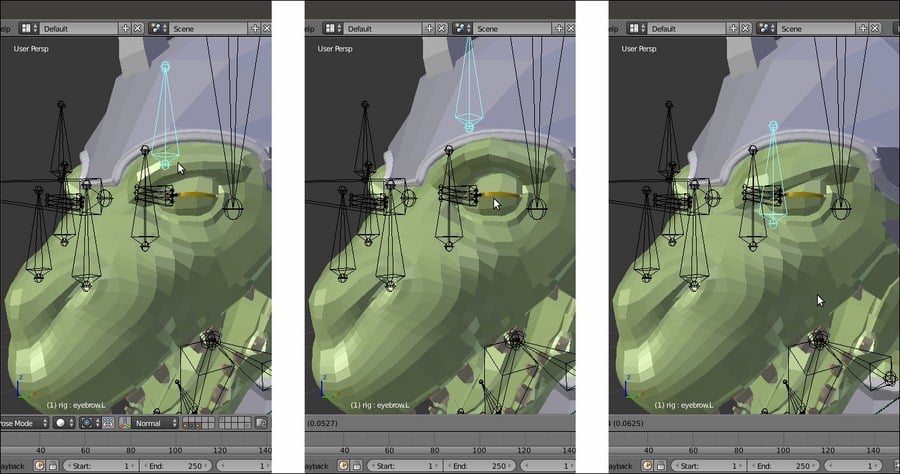
The same bone moving in two opposite directions to drive two opposite shape keys
To add shape keys and the respective drivers to the Gidiosaurus model, we used the Gidiosaurus_skinning_rigify.blend file, with the rig created by the Rigify addon. The control bones of a Rigify rig have pre-made Custom Shapes to make their identification and selection easier and are usually located in the last scene layer.
So, for the last step, I just modeled a new simple custom shape, a small Circle mesh with 16 vertices. I named it Widget_generic4 and I assigned it to all the driver bones:
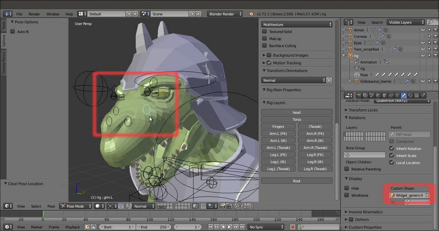
The driver bones with the new Custom Shape
Getting ready
Start from the previously saved Gidiosaurus_shapekeys.blend file:
- Go to the Outliner and hide the Armor object.
- Select the Armature rig, switch to the Octahedral bones draw mode, and press Tab to enter Edit Mode; zoom to the character head and add six bones located as follows: two bones close to both the right and the left eyebrows, two bones close to both the sides of the grin snout area, and two bones close to the nostrils. Enable the Names item in the Skeleton subpanel under the Object Data window and rename the bones accordingly and with the correct .L or .R suffix, then be sure to have them located on the first bone layer by pressing the M key to call the Change Bone Layers pop-up.
The new bones for the shape key drivers
- Exit Edit Mode and select the Gidiosaurus mesh.
- Go to the Shape Keys subpanel under the Object Data window and expand the list window by left-clicking on the = icon at the bottom and dragging it downward.
- Now right-click on the value (0.000) at the right side of the name of the first shape key (grin.L) and from the pop-up panel, select the Add Driver item; the value is enhanced, in violet, to show that now it has a driver associated.
- Repeat the same for all the shape keys in the list except for the prop one, which has a fixed value of 1.000:
The shape keys list showing they have drivers
- Split the 3D viewport horizontally into two parts, change the upper part into a Graph Editor window, or simply switch the screen to the Animation layer (in the two files provided with the cookbook, there are actually two prepared animation screens, Animation1 and Animation2). Click on the Editing context being displayed button in the toolbar of the Graph Editor window and change it from F-Curves to Drivers.
Let's start with the expressions shape keys:
- If not already present, press the N key to open the Properties sidepanel of the Graph Editor window, then click on the Value (grin.L) top item in the drivers list at the top-left of the screen:
The Graph Editor window, at the top of the screen, with the driver f-curve
- Go to the Properties panel of the Graph Editor and, by scrolling down, find the Drivers subpanel. In the Driver Type slot, switch from the Scripted Expression item to the Averaged Value one.
- In the Ob/Bone slot, select rig and in the under slot (Name of PoseBone to use as target), select the grin.L bone.
- Going downward, in the Variable Type slot, select the Y Location item and in Space, select Local Space.
- Click on the Update Dependencies button at the top of the Drivers subpanel (the Update Dependencies function works particularly for Scripted Expression; it is quite important to use it to refresh the new setups each time).
- Go even further down and click on the Add Modifier button in the Modifier subpanel; from the Add F-Curve Modifier pop-up menu, select the Generator item.
- In the Coefficient for polynomial – x slot, change the value 1.000 to the value 20.000 (this is to re-map the declivity of the f-curve and therefore the speed of the corresponding shape key):
The N Properties Graph Editor sidepanel for the selected driver
- Now select the grin.L bone and in Pose Mode, move it upward to see the grin.L shape keys being animated on the character's snout.
- Go to the Shape Keys subpanel and right-click on the value to the right side of the grin.L shape; from the pop-up menu, select the Copy Driver item.
- Select the grin.R shape key and right-click on the value to the right; from the pop-up menu, select the Paste Driver item.
- Go to the Animation screen and switch the grin.L to the grin.R bone in the Ob/Bone field under the Drivers subpanel.
- Copy and paste the drivers for the eyebrows_up.L and eyebrows_up.R shape keys, then replace the driver bones names in the Ob/Bone field under the Drivers subpanel.
- Go to the Shape Keys subpanel under the Object Data window and set the Max value under the Range item to 0.600 for both the eyebrows_up.L and eyebrows_up.R shape keys; this is to limit the movement of the shape keys to avoid any intersection with the character's helm.
- Copy and paste the drivers for the eyebrows_down.L and eyebrows_down.R shape keys. This time, leave the same driver bone names and instead change the value of the Coefficient for polynomial – x to negative and -20.000 to invert the direction of the f-curve.
- Repeat the procedure for the snare.L and snare.R shape keys, this time switching the Variable Type from Y Location to X Location and assigning a negative -20.000 value to the snare.L driver and a positive 20.000 value to the snare.R one.
At this point, all that is left is to assign automatic drivers for the shape keys to stretch and grow muscles we created for the character's arms.
- Click on the Value (bicep.L) item in the drivers window at the left top of the Graph Editor and then go to the Properties panel on the right and then to the Drivers subpanel. In the Driver Type slot, select the Averaged Value item again; in the Variable Type slot, switch to Rotational Difference.
- In the Bone1 slot, select rig and in the slot below (Name of PoseBone to use as target), select the DEF-forearm.01.L bone; in the Bone2 slot, select rig again, and then DEF-upperarm.02.L.
- In the Graph Editor, click on a point of the f-curve to select it and then press the L key to select all the points of the f-curve; move them downward, on the y axis, by -1.400 (G | Y | -1.4 | Enter).
The triceps Rotational Difference driver
- Copy and paste the driver to the bicep.R shape key, then change the .L suffixes of the bones to the .R ones.
- Copy the bicep.L driver and paste it to the triceps.L shape key; click on the Add Modifier button under the Modifier subpanel; and from the Add F-Curve Modifier pop-up menu, select the Generator item.
- In the Coefficient for polynomial – y slot, write the value 2.300 and in the x slot, write the value -1.000 (remember that all these values in the recipe are not universal and are valid just for this Gidiosaurus model in this particular setup; the drivers values could change from character to character, so always test them on your model).
- Copy and paste to the triceps.R shape key, and change the suffixes of the bones.
- Click on the Update Dependencies button at the top of the Drivers subpanel and save the file.
Drivers assigned to bones as controllers for the shape keys are not only an effective way to create a device for animation but also a mandatory technique in the Blender pipeline workflow, where a character is usually linked into the scene from a different file and the rig gets proxified (we'll see how to do this in the next chapter). The only possible way to have access to the shape keys in a linked character is through the drivers and the rig.
As you probably already know, shape keys are often used not only for facial expressions but also to mimic the stretching and the growing of the body's muscles according to the movement of a character's limbs. In this case, their influence is automatically driven by the rotation of the respective bones through the Rotational Difference drivers that, as the name itself says, base their influence on the difference of rotation between two bones; more precisely, on the angle between them.
The Generator modifier we added is a multiplier we used to virtually modify the slope inclination of the f-curves of the drivers. The default inclination of the f-curve wasn't enough to fully map the curve itself to a driver bone movement of (almost) just one or two Blender Units (it was too slow, resulting in a required driver movement of several units to have an appreciable effect), so we increased the declivity by a factor of 20.000 to have a faster correspondence.
However, the same modifier was also used to reverse the direction of the f-curve, by using a negative value of -20.000, for example to drive the downward movement of the eyebrows, or to change the location of the curve along the y axis so as to tweak the timing of the driver influence, like in the triceps shape keys.
Therefore, by copying and pasting a driver and giving an opposite declivity at the slope of the copied one, it is possible to drive two opposite shape keys through the same bone, as for the eyebrows shape keys:
The same bone moving in two opposite directions to drive two opposite shape keys
To add shape keys and the respective drivers to the Gidiosaurus model, we used the Gidiosaurus_skinning_rigify.blend file, with the rig created by the Rigify addon. The control bones of a Rigify rig have pre-made Custom Shapes to make their identification and selection easier and are usually located in the last scene layer.
So, for the last step, I just modeled a new simple custom shape, a small Circle mesh with 16 vertices. I named it Widget_generic4 and I assigned it to all the driver bones:
The driver bones with the new Custom Shape
How to do it…
Let's start with the expressions shape keys:
- If not already present, press the N key to open the Properties sidepanel of the Graph Editor window, then click on the Value (grin.L) top item in the drivers list at the top-left of the screen:
The Graph Editor window, at the top of the screen, with the driver f-curve
- Go to the Properties panel of the Graph Editor and, by scrolling down, find the Drivers subpanel. In the Driver Type slot, switch from the Scripted Expression item to the Averaged Value one.
- In the Ob/Bone slot, select rig and in the under slot (Name of PoseBone to use as target), select the grin.L bone.
- Going downward, in the Variable Type slot, select the Y Location item and in Space, select Local Space.
- Click on the Update Dependencies button at the top of the Drivers subpanel (the Update Dependencies function works particularly for Scripted Expression; it is quite important to use it to refresh the new setups each time).
- Go even further down and click on the Add Modifier button in the Modifier subpanel; from the Add F-Curve Modifier pop-up menu, select the Generator item.
- In the Coefficient for polynomial – x slot, change the value 1.000 to the value 20.000 (this is to re-map the declivity of the f-curve and therefore the speed of the corresponding shape key):
The N Properties Graph Editor sidepanel for the selected driver
- Now select the grin.L bone and in Pose Mode, move it upward to see the grin.L shape keys being animated on the character's snout.
- Go to the Shape Keys subpanel and right-click on the value to the right side of the grin.L shape; from the pop-up menu, select the Copy Driver item.
- Select the grin.R shape key and right-click on the value to the right; from the pop-up menu, select the Paste Driver item.
- Go to the Animation screen and switch the grin.L to the grin.R bone in the Ob/Bone field under the Drivers subpanel.
- Copy and paste the drivers for the eyebrows_up.L and eyebrows_up.R shape keys, then replace the driver bones names in the Ob/Bone field under the Drivers subpanel.
- Go to the Shape Keys subpanel under the Object Data window and set the Max value under the Range item to 0.600 for both the eyebrows_up.L and eyebrows_up.R shape keys; this is to limit the movement of the shape keys to avoid any intersection with the character's helm.
- Copy and paste the drivers for the eyebrows_down.L and eyebrows_down.R shape keys. This time, leave the same driver bone names and instead change the value of the Coefficient for polynomial – x to negative and -20.000 to invert the direction of the f-curve.
- Repeat the procedure for the snare.L and snare.R shape keys, this time switching the Variable Type from Y Location to X Location and assigning a negative -20.000 value to the snare.L driver and a positive 20.000 value to the snare.R one.
At this point, all that is left is to assign automatic drivers for the shape keys to stretch and grow muscles we created for the character's arms.
- Click on the Value (bicep.L) item in the drivers window at the left top of the Graph Editor and then go to the Properties panel on the right and then to the Drivers subpanel. In the Driver Type slot, select the Averaged Value item again; in the Variable Type slot, switch to Rotational Difference.
- In the Bone1 slot, select rig and in the slot below (Name of PoseBone to use as target), select the DEF-forearm.01.L bone; in the Bone2 slot, select rig again, and then DEF-upperarm.02.L.
- In the Graph Editor, click on a point of the f-curve to select it and then press the L key to select all the points of the f-curve; move them downward, on the y axis, by -1.400 (G | Y | -1.4 | Enter).
The triceps Rotational Difference driver
- Copy and paste the driver to the bicep.R shape key, then change the .L suffixes of the bones to the .R ones.
- Copy the bicep.L driver and paste it to the triceps.L shape key; click on the Add Modifier button under the Modifier subpanel; and from the Add F-Curve Modifier pop-up menu, select the Generator item.
- In the Coefficient for polynomial – y slot, write the value 2.300 and in the x slot, write the value -1.000 (remember that all these values in the recipe are not universal and are valid just for this Gidiosaurus model in this particular setup; the drivers values could change from character to character, so always test them on your model).
- Copy and paste to the triceps.R shape key, and change the suffixes of the bones.
- Click on the Update Dependencies button at the top of the Drivers subpanel and save the file.
Drivers assigned to bones as controllers for the shape keys are not only an effective way to create a device for animation but also a mandatory technique in the Blender pipeline workflow, where a character is usually linked into the scene from a different file and the rig gets proxified (we'll see how to do this in the next chapter). The only possible way to have access to the shape keys in a linked character is through the drivers and the rig.
As you probably already know, shape keys are often used not only for facial expressions but also to mimic the stretching and the growing of the body's muscles according to the movement of a character's limbs. In this case, their influence is automatically driven by the rotation of the respective bones through the Rotational Difference drivers that, as the name itself says, base their influence on the difference of rotation between two bones; more precisely, on the angle between them.
The Generator modifier we added is a multiplier we used to virtually modify the slope inclination of the f-curves of the drivers. The default inclination of the f-curve wasn't enough to fully map the curve itself to a driver bone movement of (almost) just one or two Blender Units (it was too slow, resulting in a required driver movement of several units to have an appreciable effect), so we increased the declivity by a factor of 20.000 to have a faster correspondence.
However, the same modifier was also used to reverse the direction of the f-curve, by using a negative value of -20.000, for example to drive the downward movement of the eyebrows, or to change the location of the curve along the y axis so as to tweak the timing of the driver influence, like in the triceps shape keys.
Therefore, by copying and pasting a driver and giving an opposite declivity at the slope of the copied one, it is possible to drive two opposite shape keys through the same bone, as for the eyebrows shape keys:
The same bone moving in two opposite directions to drive two opposite shape keys
To add shape keys and the respective drivers to the Gidiosaurus model, we used the Gidiosaurus_skinning_rigify.blend file, with the rig created by the Rigify addon. The control bones of a Rigify rig have pre-made Custom Shapes to make their identification and selection easier and are usually located in the last scene layer.
So, for the last step, I just modeled a new simple custom shape, a small Circle mesh with 16 vertices. I named it Widget_generic4 and I assigned it to all the driver bones:
The driver bones with the new Custom Shape
How it works…
Drivers assigned to bones as controllers for the shape keys are not only an effective way to create a device for animation but also a mandatory technique in the Blender pipeline workflow, where a character is usually linked into the scene from a different file and the rig gets proxified (we'll see how to do this in the next chapter). The only possible way to have access to the shape keys in a linked character is through the drivers and the rig.
As you probably already know, shape keys are often used not only for facial expressions but also to mimic the stretching and the growing of the body's muscles according to the movement of a character's limbs. In this case, their influence is automatically driven by the rotation of the respective bones through the Rotational Difference drivers that, as the name itself says, base their influence on the difference of rotation between two bones; more precisely, on the angle between them.
The Generator modifier we added is a multiplier we used to virtually modify the slope inclination of the f-curves of the drivers. The default inclination of the f-curve wasn't enough to fully map the curve itself to a driver bone movement of (almost) just one or two Blender Units (it was too slow, resulting in a required driver movement of several units to have an appreciable effect), so we increased the declivity by a factor of 20.000 to have a faster correspondence.
However, the same modifier was also used to reverse the direction of the f-curve, by using a negative value of -20.000, for example to drive the downward movement of the eyebrows, or to change the location of the curve along the y axis so as to tweak the timing of the driver influence, like in the triceps shape keys.
Therefore, by copying and pasting a driver and giving an opposite declivity at the slope of the copied one, it is possible to drive two opposite shape keys through the same bone, as for the eyebrows shape keys:
The same bone moving in two opposite directions to drive two opposite shape keys
To add shape keys and the respective drivers to the Gidiosaurus model, we used the Gidiosaurus_skinning_rigify.blend file, with the rig created by the Rigify addon. The control bones of a Rigify rig have pre-made Custom Shapes to make their identification and selection easier and are usually located in the last scene layer.
So, for the last step, I just modeled a new simple custom shape, a small Circle mesh with 16 vertices. I named it Widget_generic4 and I assigned it to all the driver bones:
The driver bones with the new Custom Shape
There's more…
To add shape keys and the respective drivers to the Gidiosaurus model, we used the Gidiosaurus_skinning_rigify.blend file, with the rig created by the Rigify addon. The control bones of a Rigify rig have pre-made Custom Shapes to make their identification and selection easier and are usually located in the last scene layer.
So, for the last step, I just modeled a new simple custom shape, a small Circle mesh with 16 vertices. I named it Widget_generic4 and I assigned it to all the driver bones:
The driver bones with the new Custom Shape
Often, it is very useful to put movement limitations on the bones of a rig, for several reasons—usually, to make them easier to work with, but also to establish a maximum range for the rotation of the limbs or other parts like in the mandible or the eyelids.
Two types of limits for the bones are: by the Transform locks, and by bone constraints.
Let's start with the Transform locks:
- Select the eyebrow.L bone and if not already present, press the N key to call the 3D viewport Properties sidepanel. Go to the Transform subpanel, which is the first entry at the top, or also to the Transform Locks subpanel under the Bone window in the main Properties panel to the right of the screen:

The Transform subpanel in the N Properties sidepanel and the corresponding Transform Locks subpanel under the main Properties panel
- Click on the lock icon to the right side of the properties; for this bone (which, if you recall, is the driver control object for the left up and down eyebrow shape keys), we want to lock all the possible transformations except for the movement on its y axis, so the Location Y lock button is the only one that should remain untouched:

Setting the axis Transform locks for the Location, Rotation, and Scale
If you now try to move the eyebrow.L bone, you will notice its movement is constrained only to its local y axis; the movement is directed by the Roll orientation of the bone in Edit Mode (and not by the Normal item enabled in the Transform Orientation button on the viewport toolbar); enable the Axes item in the Display subpanel under the Object Data window to see this.
Having locked the other two axes, it's no longer necessary to use the widget arrow to move the bone on its local y axis but it's enough to simply press the G key and then move the mouse instead.
And now, let's see limits by constraints.
- Go to the Bone Constraints window and assign a Limit Location constraint to the eyebrow.L bone.
- Check the Minimum X and Maximum X, Minimum Y, and Maximum Y, and Minimum Z and Maximum Z items. Leave the values for the x and z axes as they are, change Minimum Y to negative -0.050, and change Maximum Y to positive 0.050 (again, remember that these values are valid just for this file).
- In the Convert slot, change the Owner Space item to Local Space:

The assigned Limit Location constraint subpanel under the main Properties panel
In Chapter 1, Modeling the Character's Base Mesh, we enabled the Copy Attributes Menu add-on in User Preferences and then we saved the User Settings, so I'm taking for granted that you have the script still enabled.
Therefore, we do the following:
- Select the eyebrow.R bone and then Shift-select the eyebrow.L bone. Press Ctrl + C and from the Copy Attributes pop-up menu, select the Copy Bone Constraints item.
- Select the grin.L and grin.R bones and then Shift-select the eyebrow.L bone. Once again, press Ctrl + C | Copy Bone Constraints, and in the two copied constraints, set the Minimum Y value to 0.000.
- Select the nostril.L and .R bones and Shift-select the grin.L bone, then press Ctrl + C | Copy Bone Constraints. This time, set both the Y values to 0.000 and Minimum X for the nostril.L bone to negative -0.050 and the Maximum X for the nostril.R bone to positive 0.050.
- Save the file.
Several other movement constraints have been added to different bones in the rig, for example the jaw bone, or the eyelid controllers, but especially to the eye bones, to limit the range of possible rotations. To have a look at the various settings, just open the Gidiosaurus_limits.blend file.
Getting ready
Load the Gidiosaurus_shapekeys.blend file, select the Armature, and go in Pose Mode.
Let's start with the Transform locks:
- Select the eyebrow.L bone and if not already present, press the N key to call the 3D viewport Properties sidepanel. Go to the Transform subpanel, which is the first entry at the top, or also to the Transform Locks subpanel under the Bone window in the main Properties panel to the right of the screen:
The Transform subpanel in the N Properties sidepanel and the corresponding Transform Locks subpanel under the main Properties panel
- Click on the lock icon to the right side of the properties; for this bone (which, if you recall, is the driver control object for the left up and down eyebrow shape keys), we want to lock all the possible transformations except for the movement on its y axis, so the Location Y lock button is the only one that should remain untouched:
Setting the axis Transform locks for the Location, Rotation, and Scale
If you now try to move the eyebrow.L bone, you will notice its movement is constrained only to its local y axis; the movement is directed by the Roll orientation of the bone in Edit Mode (and not by the Normal item enabled in the Transform Orientation button on the viewport toolbar); enable the Axes item in the Display subpanel under the Object Data window to see this.
Having locked the other two axes, it's no longer necessary to use the widget arrow to move the bone on its local y axis but it's enough to simply press the G key and then move the mouse instead.
And now, let's see limits by constraints.
- Go to the Bone Constraints window and assign a Limit Location constraint to the eyebrow.L bone.
- Check the Minimum X and Maximum X, Minimum Y, and Maximum Y, and Minimum Z and Maximum Z items. Leave the values for the x and z axes as they are, change Minimum Y to negative -0.050, and change Maximum Y to positive 0.050 (again, remember that these values are valid just for this file).
- In the Convert slot, change the Owner Space item to Local Space:
The assigned Limit Location constraint subpanel under the main Properties panel
In Chapter 1, Modeling the Character's Base Mesh, we enabled the Copy Attributes Menu add-on in User Preferences and then we saved the User Settings, so I'm taking for granted that you have the script still enabled.
Therefore, we do the following:
- Select the eyebrow.R bone and then Shift-select the eyebrow.L bone. Press Ctrl + C and from the Copy Attributes pop-up menu, select the Copy Bone Constraints item.
- Select the grin.L and grin.R bones and then Shift-select the eyebrow.L bone. Once again, press Ctrl + C | Copy Bone Constraints, and in the two copied constraints, set the Minimum Y value to 0.000.
- Select the nostril.L and .R bones and Shift-select the grin.L bone, then press Ctrl + C | Copy Bone Constraints. This time, set both the Y values to 0.000 and Minimum X for the nostril.L bone to negative -0.050 and the Maximum X for the nostril.R bone to positive 0.050.
- Save the file.
Several other movement constraints have been added to different bones in the rig, for example the jaw bone, or the eyelid controllers, but especially to the eye bones, to limit the range of possible rotations. To have a look at the various settings, just open the Gidiosaurus_limits.blend file.
How to do it…
Let's start with the Transform locks:
- Select the eyebrow.L bone and if not already present, press the N key to call the 3D viewport Properties sidepanel. Go to the Transform subpanel, which is the first entry at the top, or also to the Transform Locks subpanel under the Bone window in the main Properties panel to the right of the screen:
The Transform subpanel in the N Properties sidepanel and the corresponding Transform Locks subpanel under the main Properties panel
- Click on the lock icon to the right side of the properties; for this bone (which, if you recall, is the driver control object for the left up and down eyebrow shape keys), we want to lock all the possible transformations except for the movement on its y axis, so the Location Y lock button is the only one that should remain untouched:
Setting the axis Transform locks for the Location, Rotation, and Scale
If you now try to move the eyebrow.L bone, you will notice its movement is constrained only to its local y axis; the movement is directed by the Roll orientation of the bone in Edit Mode (and not by the Normal item enabled in the Transform Orientation button on the viewport toolbar); enable the Axes item in the Display subpanel under the Object Data window to see this.
Having locked the other two axes, it's no longer necessary to use the widget arrow to move the bone on its local y axis but it's enough to simply press the G key and then move the mouse instead.
And now, let's see limits by constraints.
- Go to the Bone Constraints window and assign a Limit Location constraint to the eyebrow.L bone.
- Check the Minimum X and Maximum X, Minimum Y, and Maximum Y, and Minimum Z and Maximum Z items. Leave the values for the x and z axes as they are, change Minimum Y to negative -0.050, and change Maximum Y to positive 0.050 (again, remember that these values are valid just for this file).
- In the Convert slot, change the Owner Space item to Local Space:
The assigned Limit Location constraint subpanel under the main Properties panel
In Chapter 1, Modeling the Character's Base Mesh, we enabled the Copy Attributes Menu add-on in User Preferences and then we saved the User Settings, so I'm taking for granted that you have the script still enabled.
Therefore, we do the following:
- Select the eyebrow.R bone and then Shift-select the eyebrow.L bone. Press Ctrl + C and from the Copy Attributes pop-up menu, select the Copy Bone Constraints item.
- Select the grin.L and grin.R bones and then Shift-select the eyebrow.L bone. Once again, press Ctrl + C | Copy Bone Constraints, and in the two copied constraints, set the Minimum Y value to 0.000.
- Select the nostril.L and .R bones and Shift-select the grin.L bone, then press Ctrl + C | Copy Bone Constraints. This time, set both the Y values to 0.000 and Minimum X for the nostril.L bone to negative -0.050 and the Maximum X for the nostril.R bone to positive 0.050.
- Save the file.
Several other movement constraints have been added to different bones in the rig, for example the jaw bone, or the eyelid controllers, but especially to the eye bones, to limit the range of possible rotations. To have a look at the various settings, just open the Gidiosaurus_limits.blend file.
This is a really simple trick that can add a lot of life to the facial expressions of an animated model, making the eyelids follow some of the movement of the eyeballs.
Following on from the previous recipes, open the Gidiosaurus_limits.blend file:
- If not already selected, select the Armature and enter Pose Mode.
- In the Object Data window, go to the Skeleton subpanel and enable the 30th bone layer, to show the deforming bones.
- In the Display subpanel, switch the bones' drawing mode from Wire to Octahedral:

The Skeleton subpanel with the bone layers
Now zoom to the character's head and continue with the following steps:
- Select the eyelid_upper.L bone and go to the Bone Constraints window; assign a Copy Rotation constraint.
- In the Target field, select the rig item, and in the Bone field, select the eye.L bone item. Set Space = Pose Space to Pose Space.
- Set the Influence slider value to 0.300.
- Select the eyelid_bottom.L bone and Shift-select the eyelid_upper.L bone, then press Ctrl + C | Copy Bone Constraint.
- Select the eyelid_upper.R bone and repeat the procedure but with eye.R as the target bone; copy the constraint to the eyelid_bottom.R bone:

The eyelids slightly following the eye movements
- Save the file.
Getting ready
Following on from the previous recipes, open the Gidiosaurus_limits.blend file:
- If not already selected, select the Armature and enter Pose Mode.
- In the Object Data window, go to the Skeleton subpanel and enable the 30th bone layer, to show the deforming bones.
- In the Display subpanel, switch the bones' drawing mode from Wire to Octahedral:
The Skeleton subpanel with the bone layers
Now zoom to the character's head and continue with the following steps:
- Select the eyelid_upper.L bone and go to the Bone Constraints window; assign a Copy Rotation constraint.
- In the Target field, select the rig item, and in the Bone field, select the eye.L bone item. Set Space = Pose Space to Pose Space.
- Set the Influence slider value to 0.300.
- Select the eyelid_bottom.L bone and Shift-select the eyelid_upper.L bone, then press Ctrl + C | Copy Bone Constraint.
- Select the eyelid_upper.R bone and repeat the procedure but with eye.R as the target bone; copy the constraint to the eyelid_bottom.R bone:
The eyelids slightly following the eye movements
- Save the file.
How to do it…
Now zoom to the character's head and continue with the following steps:
- Select the eyelid_upper.L bone and go to the Bone Constraints window; assign a Copy Rotation constraint.
- In the Target field, select the rig item, and in the Bone field, select the eye.L bone item. Set Space = Pose Space to Pose Space.
- Set the Influence slider value to 0.300.
- Select the eyelid_bottom.L bone and Shift-select the eyelid_upper.L bone, then press Ctrl + C | Copy Bone Constraint.
- Select the eyelid_upper.R bone and repeat the procedure but with eye.R as the target bone; copy the constraint to the eyelid_bottom.R bone:
The eyelids slightly following the eye movements
- Save the file.
In Chapter 3, Polygonal Modeling of the Character's Accessories, in the Using the Mesh to Curve technique to add details recipe, you already saw how to use this technique as a modeling tool. In this recipe, we'll use the same technique but in the opposite direction—to add rivets around the perimeter of the borders of the different Armor parts.
Re-open the Gidiosaurus_limits.blend file; the first thing to do is to model a very lowpoly rivet object to be duplicated on the Armor surface:
- Switch to an empty scene layer, press Shift + C to place the 3D Cursor at the center of the grid, and add a Cube primitive mesh. Enter Edit Mode and delete the bottom face, then scale the remaining faces by a value of 0.100 twice, then one last time by 0.500. Move the top face downward to flatten the overall shape a bit and scale the same face by 0.700.
- Press A to select all the vertices and W to choose the Subdivide Smooth item from the Specials pop-up menu, then delete the middle horizontal edgeloop.
- Put the pivot on the 3D Cursor and while still in Edit Mode, rotate all the vertices by 90° on the x axis.
- Select the bottom edgeloop and press Shift + S | Cursor to Selected. Exit Edit Mode and click on the Set Origin button under the Tool tab to select the Origin to 3D Cursor item.
- Click on the Smooth button under the Shading item and in the Outliner, rename the rivet object. Once again, place the 3D Cursor at the center of the grid and the rivet at the Cursor location; press Ctrl + A to apply the Rotation & Scale option.
- Enable the scene layer with the Armor on it, and in the Outliner, hide the rig.
Now, let's create the guides to duplicate the rivets on:
- Select the Armor object and press Shift + D to duplicate it, then place the duplicate Armor.001 object on the scene layer of the rivet. Go to the Shape Keys sidepanel under the Object Data window and delete the Armor_fix first and then the Basis shape keys.
- Go to the Object Modifiers window, remove the Armature modifier, and apply the Subdivision Surface modifier with a Subdivision level of 2.
- Enter Edit Mode and start to select the edgeloops on the different Armor parts in areas where you want to add the rivet rows (Alt + right-click for the first one, then Alt + Shift + right-click). As usual, it's enough to work only on one half of the mesh:

The Armor mesh in Edit Mode with the selected edge-loops
- Press Shift + D and soon after, click the right mouse button to duplicate the selected edgeloops without moving them, then press the P key to separate them from the Armor.001 object (in the Separate pop-up menu, choose the Selection item).
- Exit Edit Mode and delete the Armor.001 object, or if you don't have problems with big file sizes, move it to a different scene layer to keep it for future refinements. In this case, you can save the edge-loops selection as a vertex group named rivets.
- Select the Armor.002 object (the duplicated and separated edgeloops) and enter Edit Mode; make the necessary adjustments to the edgeloops by deleting the unnecessary vertices, for example the backsides of the plates, and disconnect the welded edgeloops by deleting the common vertices or connecting them where required edges are missing:

Cleaning the edge-loops of the duplicated Armor.002 mesh
- Press A to select all the vertices and then go to the Tools tab under the Tool Shelf. Go to the LoopTools subpanel and press the Space button to evenly space the vertices along the edgeloops.
- Exit Edit Mode and press Alt + C; in the Convert to pop-up menu, select the first item, Curve from Mesh/Text. The mesh edgeloops actually get converted into a Curve object, as you can see in the Object Data window under the main Properties panel to the right of the UI. Click on the Fill slot to select the Full item.
- Now the tedious part (but not difficult, just a little tedious); in Edit Mode again, put the mouse on one of the points and by pressing the L key, select each separate part of the Curve, then press P to separate the whole selected part. This way, you are going to obtain 16 separated Curve objects.
- Select the rivet object and go to the Object Modifiers window; assign an Array modifier with Fit Type = Fit Length, Length = 0.50, and Relative Offset X = 3.000. Collapse the panel.
- Assign a Curve modifier, then in the Object field select the Armor.002 curve. Leave the panel expanded.
- Assign a Mirror modifier and collapse the panel:

The rivet object instanced on the mirrored curve object
- In the viewport area, zoom to each curve to check for the correct tilting of the points; if necessary, select the curve, enter Edit Mode, select all the points, press Ctrl + T, and move the mouse to rotate the tilting of the curve's points until the instanced rivets are correctly rotated/aligned with the surface of the main Armor mesh:

Tilting the curve's points
If necessary, you can also select individual points of the curve to tweak the orientation of only a part of the instanced rivets, even of single rivets at once; this has been done for part of the helm and for the spaulders, especially.
- In the Outliner, re-select the rivet and press Shift + D to duplicate it, then in the Object Modifiers window, under the Curve modifier panel, select the Armor.003 item in the Object field.
- Once again, zoom to the curve and if necessary, fix the curve tilting and also adjust the Length value of the Array modifier (for the Armor.003 curve it has been raised to 0.59) and the Relative Offset value. By selecting all the points and pressing W, you can also select the Switch Direction item in the Specials menu.

The rivets on the helm object
- Duplicate the rivet and repeat the procedure changing the curve name in the modifier for each curve object and so on. At the end, you should have 16 copies of the rivet as well.
At this point, if required, we can still make some modification to the rivet mesh; in my case, I just subdivided it a bit more, then deleted some useless edgeloop, made it rounder, and extruded the open side a bit more.
Now that the rivet is ready, select all the rivet copies (so that the modified one is the active object, that is the last selected) and press Ctrl + L | Object Data to share the modifications between them.
Leaving everything selected, press U | Object & Data to make them single users again (this is necessary for the next step with the modifiers).
- When you are done, select all the rivets one at a time in the Outliner and apply all the Array and the Curve modifiers.
- Join all the rivets into a single object (select all and press Ctrl + J) and in Edit Mode, delete the unnecessary or overlapping ones, keeping only the rivets that really add to the Armor look. Then, apply all the Mirror modifiers:

The completed rivets
- Select the Armor object and then Shift-select the rivets object, press Ctrl + Tab to go in Weight Paint mode and click on the Transfer Weights button under the Tools tab.
- Exit Weight Paint mode and assign an Armature modifier to the rivets object, select rig in the Object field.
- Save the file as
Gidiosaurus_final_detailing.blend.
At this point, the Gidiosaurus model is ready to be animated, but some minor adjustments are still missing and can be added.
I won't go into the details about these additions, they are all processes you have already seen in the previous chapters and recipes, so this is simply a showcase:
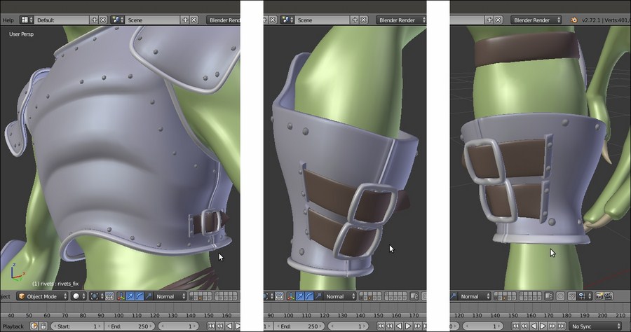
The modeled tiers and the rivets
- The tier attachments on the Armor's vambraces and on the greaves have been refined by adding smaller rivets, and new tiers have been added to the sides of the Armor chest plate. Also, the opening seams in the Armor parts have been modeled under each tier location.
- The Armor decorations have been separated as a new object (the Armor_decorations item in the Outliner) and simplified by deleting as many edgeloops as possible without altering their basic shape:

The simplified decorations in Edit Mode
- The Armor's shape also has been tweaked even further through the Armor_fix shape key to adjust some overlaps that were occurring during the movements of the spaulders and in the stomach area too. The same shape key has been repeated also on the decorations and on the rivets objects for the areas of interest.
- A bit of asymmetry has been introduced in the Gidiosaurus mesh by assigning a Lattice modifier to the character, and slightly modifying the shape on the left side, then applying the modifier as a shape key (the Apply as Shape Key button):

The asymmetry lattice
- Finally, after some test renders, I realized that the teeth and the inside of the mouth of the Gidiosaurus still needed refinements, so I made some more adjustments to the prop shape key by making the teeth bigger and bolder, and the inner mouth more organic-looking and smooth:

The modified teeth and inner mouth
Be aware that almost in every modeled object there is still room for improvement, and that's okay, it's not a sign of a bad job! This sort of improvement is done all the time and is simply part of the working experience.
Getting ready
Re-open the Gidiosaurus_limits.blend file; the first thing to do is to model a very lowpoly rivet object to be duplicated on the Armor surface:
- Switch to an empty scene layer, press Shift + C to place the 3D Cursor at the center of the grid, and add a Cube primitive mesh. Enter Edit Mode and delete the bottom face, then scale the remaining faces by a value of 0.100 twice, then one last time by 0.500. Move the top face downward to flatten the overall shape a bit and scale the same face by 0.700.
- Press A to select all the vertices and W to choose the Subdivide Smooth item from the Specials pop-up menu, then delete the middle horizontal edgeloop.
- Put the pivot on the 3D Cursor and while still in Edit Mode, rotate all the vertices by 90° on the x axis.
- Select the bottom edgeloop and press Shift + S | Cursor to Selected. Exit Edit Mode and click on the Set Origin button under the Tool tab to select the Origin to 3D Cursor item.
- Click on the Smooth button under the Shading item and in the Outliner, rename the rivet object. Once again, place the 3D Cursor at the center of the grid and the rivet at the Cursor location; press Ctrl + A to apply the Rotation & Scale option.
- Enable the scene layer with the Armor on it, and in the Outliner, hide the rig.
Now, let's create the guides to duplicate the rivets on:
- Select the Armor object and press Shift + D to duplicate it, then place the duplicate Armor.001 object on the scene layer of the rivet. Go to the Shape Keys sidepanel under the Object Data window and delete the Armor_fix first and then the Basis shape keys.
- Go to the Object Modifiers window, remove the Armature modifier, and apply the Subdivision Surface modifier with a Subdivision level of 2.
- Enter Edit Mode and start to select the edgeloops on the different Armor parts in areas where you want to add the rivet rows (Alt + right-click for the first one, then Alt + Shift + right-click). As usual, it's enough to work only on one half of the mesh:
The Armor mesh in Edit Mode with the selected edge-loops
- Press Shift + D and soon after, click the right mouse button to duplicate the selected edgeloops without moving them, then press the P key to separate them from the Armor.001 object (in the Separate pop-up menu, choose the Selection item).
- Exit Edit Mode and delete the Armor.001 object, or if you don't have problems with big file sizes, move it to a different scene layer to keep it for future refinements. In this case, you can save the edge-loops selection as a vertex group named rivets.
- Select the Armor.002 object (the duplicated and separated edgeloops) and enter Edit Mode; make the necessary adjustments to the edgeloops by deleting the unnecessary vertices, for example the backsides of the plates, and disconnect the welded edgeloops by deleting the common vertices or connecting them where required edges are missing:
Cleaning the edge-loops of the duplicated Armor.002 mesh
- Press A to select all the vertices and then go to the Tools tab under the Tool Shelf. Go to the LoopTools subpanel and press the Space button to evenly space the vertices along the edgeloops.
- Exit Edit Mode and press Alt + C; in the Convert to pop-up menu, select the first item, Curve from Mesh/Text. The mesh edgeloops actually get converted into a Curve object, as you can see in the Object Data window under the main Properties panel to the right of the UI. Click on the Fill slot to select the Full item.
- Now the tedious part (but not difficult, just a little tedious); in Edit Mode again, put the mouse on one of the points and by pressing the L key, select each separate part of the Curve, then press P to separate the whole selected part. This way, you are going to obtain 16 separated Curve objects.
- Select the rivet object and go to the Object Modifiers window; assign an Array modifier with Fit Type = Fit Length, Length = 0.50, and Relative Offset X = 3.000. Collapse the panel.
- Assign a Curve modifier, then in the Object field select the Armor.002 curve. Leave the panel expanded.
- Assign a Mirror modifier and collapse the panel:
The rivet object instanced on the mirrored curve object
- In the viewport area, zoom to each curve to check for the correct tilting of the points; if necessary, select the curve, enter Edit Mode, select all the points, press Ctrl + T, and move the mouse to rotate the tilting of the curve's points until the instanced rivets are correctly rotated/aligned with the surface of the main Armor mesh:
Tilting the curve's points
If necessary, you can also select individual points of the curve to tweak the orientation of only a part of the instanced rivets, even of single rivets at once; this has been done for part of the helm and for the spaulders, especially.
- In the Outliner, re-select the rivet and press Shift + D to duplicate it, then in the Object Modifiers window, under the Curve modifier panel, select the Armor.003 item in the Object field.
- Once again, zoom to the curve and if necessary, fix the curve tilting and also adjust the Length value of the Array modifier (for the Armor.003 curve it has been raised to 0.59) and the Relative Offset value. By selecting all the points and pressing W, you can also select the Switch Direction item in the Specials menu.
The rivets on the helm object
- Duplicate the rivet and repeat the procedure changing the curve name in the modifier for each curve object and so on. At the end, you should have 16 copies of the rivet as well.
At this point, if required, we can still make some modification to the rivet mesh; in my case, I just subdivided it a bit more, then deleted some useless edgeloop, made it rounder, and extruded the open side a bit more.
Now that the rivet is ready, select all the rivet copies (so that the modified one is the active object, that is the last selected) and press Ctrl + L | Object Data to share the modifications between them.
Leaving everything selected, press U | Object & Data to make them single users again (this is necessary for the next step with the modifiers).
- When you are done, select all the rivets one at a time in the Outliner and apply all the Array and the Curve modifiers.
- Join all the rivets into a single object (select all and press Ctrl + J) and in Edit Mode, delete the unnecessary or overlapping ones, keeping only the rivets that really add to the Armor look. Then, apply all the Mirror modifiers:
The completed rivets
- Select the Armor object and then Shift-select the rivets object, press Ctrl + Tab to go in Weight Paint mode and click on the Transfer Weights button under the Tools tab.
- Exit Weight Paint mode and assign an Armature modifier to the rivets object, select rig in the Object field.
- Save the file as
Gidiosaurus_final_detailing.blend.
At this point, the Gidiosaurus model is ready to be animated, but some minor adjustments are still missing and can be added.
I won't go into the details about these additions, they are all processes you have already seen in the previous chapters and recipes, so this is simply a showcase:
The modeled tiers and the rivets
- The tier attachments on the Armor's vambraces and on the greaves have been refined by adding smaller rivets, and new tiers have been added to the sides of the Armor chest plate. Also, the opening seams in the Armor parts have been modeled under each tier location.
- The Armor decorations have been separated as a new object (the Armor_decorations item in the Outliner) and simplified by deleting as many edgeloops as possible without altering their basic shape:
The simplified decorations in Edit Mode
- The Armor's shape also has been tweaked even further through the Armor_fix shape key to adjust some overlaps that were occurring during the movements of the spaulders and in the stomach area too. The same shape key has been repeated also on the decorations and on the rivets objects for the areas of interest.
- A bit of asymmetry has been introduced in the Gidiosaurus mesh by assigning a Lattice modifier to the character, and slightly modifying the shape on the left side, then applying the modifier as a shape key (the Apply as Shape Key button):
The asymmetry lattice
- Finally, after some test renders, I realized that the teeth and the inside of the mouth of the Gidiosaurus still needed refinements, so I made some more adjustments to the prop shape key by making the teeth bigger and bolder, and the inner mouth more organic-looking and smooth:
The modified teeth and inner mouth
Be aware that almost in every modeled object there is still room for improvement, and that's okay, it's not a sign of a bad job! This sort of improvement is done all the time and is simply part of the working experience.
How to do it…
Now, let's create the guides to duplicate the rivets on:
- Select the Armor object and press Shift + D to duplicate it, then place the duplicate Armor.001 object on the scene layer of the rivet. Go to the Shape Keys sidepanel under the Object Data window and delete the Armor_fix first and then the Basis shape keys.
- Go to the Object Modifiers window, remove the Armature modifier, and apply the Subdivision Surface modifier with a Subdivision level of 2.
- Enter Edit Mode and start to select the edgeloops on the different Armor parts in areas where you want to add the rivet rows (Alt + right-click for the first one, then Alt + Shift + right-click). As usual, it's enough to work only on one half of the mesh:
The Armor mesh in Edit Mode with the selected edge-loops
- Press Shift + D and soon after, click the right mouse button to duplicate the selected edgeloops without moving them, then press the P key to separate them from the Armor.001 object (in the Separate pop-up menu, choose the Selection item).
- Exit Edit Mode and delete the Armor.001 object, or if you don't have problems with big file sizes, move it to a different scene layer to keep it for future refinements. In this case, you can save the edge-loops selection as a vertex group named rivets.
- Select the Armor.002 object (the duplicated and separated edgeloops) and enter Edit Mode; make the necessary adjustments to the edgeloops by deleting the unnecessary vertices, for example the backsides of the plates, and disconnect the welded edgeloops by deleting the common vertices or connecting them where required edges are missing:
Cleaning the edge-loops of the duplicated Armor.002 mesh
- Press A to select all the vertices and then go to the Tools tab under the Tool Shelf. Go to the LoopTools subpanel and press the Space button to evenly space the vertices along the edgeloops.
- Exit Edit Mode and press Alt + C; in the Convert to pop-up menu, select the first item, Curve from Mesh/Text. The mesh edgeloops actually get converted into a Curve object, as you can see in the Object Data window under the main Properties panel to the right of the UI. Click on the Fill slot to select the Full item.
- Now the tedious part (but not difficult, just a little tedious); in Edit Mode again, put the mouse on one of the points and by pressing the L key, select each separate part of the Curve, then press P to separate the whole selected part. This way, you are going to obtain 16 separated Curve objects.
- Select the rivet object and go to the Object Modifiers window; assign an Array modifier with Fit Type = Fit Length, Length = 0.50, and Relative Offset X = 3.000. Collapse the panel.
- Assign a Curve modifier, then in the Object field select the Armor.002 curve. Leave the panel expanded.
- Assign a Mirror modifier and collapse the panel:
The rivet object instanced on the mirrored curve object
- In the viewport area, zoom to each curve to check for the correct tilting of the points; if necessary, select the curve, enter Edit Mode, select all the points, press Ctrl + T, and move the mouse to rotate the tilting of the curve's points until the instanced rivets are correctly rotated/aligned with the surface of the main Armor mesh:
Tilting the curve's points
If necessary, you can also select individual points of the curve to tweak the orientation of only a part of the instanced rivets, even of single rivets at once; this has been done for part of the helm and for the spaulders, especially.
- In the Outliner, re-select the rivet and press Shift + D to duplicate it, then in the Object Modifiers window, under the Curve modifier panel, select the Armor.003 item in the Object field.
- Once again, zoom to the curve and if necessary, fix the curve tilting and also adjust the Length value of the Array modifier (for the Armor.003 curve it has been raised to 0.59) and the Relative Offset value. By selecting all the points and pressing W, you can also select the Switch Direction item in the Specials menu.
The rivets on the helm object
- Duplicate the rivet and repeat the procedure changing the curve name in the modifier for each curve object and so on. At the end, you should have 16 copies of the rivet as well.
At this point, if required, we can still make some modification to the rivet mesh; in my case, I just subdivided it a bit more, then deleted some useless edgeloop, made it rounder, and extruded the open side a bit more.
Now that the rivet is ready, select all the rivet copies (so that the modified one is the active object, that is the last selected) and press Ctrl + L | Object Data to share the modifications between them.
Leaving everything selected, press U | Object & Data to make them single users again (this is necessary for the next step with the modifiers).
- When you are done, select all the rivets one at a time in the Outliner and apply all the Array and the Curve modifiers.
- Join all the rivets into a single object (select all and press Ctrl + J) and in Edit Mode, delete the unnecessary or overlapping ones, keeping only the rivets that really add to the Armor look. Then, apply all the Mirror modifiers:
The completed rivets
- Select the Armor object and then Shift-select the rivets object, press Ctrl + Tab to go in Weight Paint mode and click on the Transfer Weights button under the Tools tab.
- Exit Weight Paint mode and assign an Armature modifier to the rivets object, select rig in the Object field.
- Save the file as
Gidiosaurus_final_detailing.blend.
At this point, the Gidiosaurus model is ready to be animated, but some minor adjustments are still missing and can be added.
I won't go into the details about these additions, they are all processes you have already seen in the previous chapters and recipes, so this is simply a showcase:
The modeled tiers and the rivets
- The tier attachments on the Armor's vambraces and on the greaves have been refined by adding smaller rivets, and new tiers have been added to the sides of the Armor chest plate. Also, the opening seams in the Armor parts have been modeled under each tier location.
- The Armor decorations have been separated as a new object (the Armor_decorations item in the Outliner) and simplified by deleting as many edgeloops as possible without altering their basic shape:
The simplified decorations in Edit Mode
- The Armor's shape also has been tweaked even further through the Armor_fix shape key to adjust some overlaps that were occurring during the movements of the spaulders and in the stomach area too. The same shape key has been repeated also on the decorations and on the rivets objects for the areas of interest.
- A bit of asymmetry has been introduced in the Gidiosaurus mesh by assigning a Lattice modifier to the character, and slightly modifying the shape on the left side, then applying the modifier as a shape key (the Apply as Shape Key button):
The asymmetry lattice
- Finally, after some test renders, I realized that the teeth and the inside of the mouth of the Gidiosaurus still needed refinements, so I made some more adjustments to the prop shape key by making the teeth bigger and bolder, and the inner mouth more organic-looking and smooth:
The modified teeth and inner mouth
Be aware that almost in every modeled object there is still room for improvement, and that's okay, it's not a sign of a bad job! This sort of improvement is done all the time and is simply part of the working experience.
There's more…
At this point, the Gidiosaurus model is ready to be animated, but some minor adjustments are still missing and can be added.
I won't go into the details about these additions, they are all processes you have already seen in the previous chapters and recipes, so this is simply a showcase:
The modeled tiers and the rivets
- The tier attachments on the Armor's vambraces and on the greaves have been refined by adding smaller rivets, and new tiers have been added to the sides of the Armor chest plate. Also, the opening seams in the Armor parts have been modeled under each tier location.
- The Armor decorations have been separated as a new object (the Armor_decorations item in the Outliner) and simplified by deleting as many edgeloops as possible without altering their basic shape:
The simplified decorations in Edit Mode
- The Armor's shape also has been tweaked even further through the Armor_fix shape key to adjust some overlaps that were occurring during the movements of the spaulders and in the stomach area too. The same shape key has been repeated also on the decorations and on the rivets objects for the areas of interest.
- A bit of asymmetry has been introduced in the Gidiosaurus mesh by assigning a Lattice modifier to the character, and slightly modifying the shape on the left side, then applying the modifier as a shape key (the Apply as Shape Key button):
The asymmetry lattice
- Finally, after some test renders, I realized that the teeth and the inside of the mouth of the Gidiosaurus still needed refinements, so I made some more adjustments to the prop shape key by making the teeth bigger and bolder, and the inner mouth more organic-looking and smooth:
The modified teeth and inner mouth
Be aware that almost in every modeled object there is still room for improvement, and that's okay, it's not a sign of a bad job! This sort of improvement is done all the time and is simply part of the working experience.
In this chapter, we will cover the following recipes:
- Linking the character and making a proxy
- Creating a simple walk cycle for the character by assigning keys to the bones
- Tweaking the actions in Graph Editor
- Using the Non Linear Action Editor to mix different actions
There are literally a plethora of tutorials and manuals about animation principles in general, and in Blender in particular, on the Web and in bookstores, so this one is going to be just a very easy chapter, mainly about the technical aspects of creating a simple animation with the rigged Gidiosaurus character, following the most usual pipeline commonly used in Blender (at least for the open movies).
The habit of linking assets from library files is the most useful and used, I would say, not only in a Blender based workflow, but also in the industry. A linked asset, in our case a creature character, can be placed and animated even if not already completed in all its parts, thus it allows a team to work almost at the same time on the different aspects. In our case, the Gidiosaurus is still missing texturing and shaders, but can already be placed on stage and animated anyway.
To link an asset in Blender and keep the possibility of animating it through a rig, we must make a proxy of the rig itself. A proxy object overrides the animation controls of a linked object in a non-destructive way, so that an animator can animate it locally to the .blend file the rigged character has been linked to. This way, the linked character object retains all its original information and is only locally altered by the proxy object scene.
As the first thing, we must prepare the library, so open the Gidiosaurus_final_detailing.blend file:
- Go to the Outliner and select the Gidiosaurus_lowres mesh, then also Shift-select the Armor, the Armor_decorations, the rivets, the Eyes, and the Corneas objects.
- Press Ctrl + G, and all the selected objects are outlined in green to show that now they belong to a group, in this case, to the same group we created just now.
- Go to the Object window and in the Groups subpanel, change the generic default Group name to Gidiosaurus.

Creating a Group and assigning all the selected objects to it
- Go to the Outliner and click on the eye icon to the side of the rig item to make it visible again, and then click on the rig item itself to select it.
- Press Ctrl + Tab to go out of Pose Mode and go to the Groups subpanel under the Object window again. Click on the Add to Group button and in the pop-up menu, select the Gidiosaurus item (in this case, the only group already created). The rig is outlined in green as well:

The rig assigned to the group as well
- Click again on the Restrict view-port visibility button (the one with the eye icon) to the side of the rig item to hide it and save the file as
Gidiosaurus_library.blend.
- Click on the File item in the main menu bar, select the New item, and confirm by clicking on the Reload Start-Up File pop-up (or just press Ctrl + N).
- Select the default Cube and delete it, then go to File | Link (or press Ctrl + Alt + O). Browse and click on the
Gidiosaurus_library.blendfile, then click on the Group folder item, and finally click on the Gidiosaurus item. Click on the Link from Library button to the top right of the screen.A new object has appeared at the 3D Cursor location (that should be placed at the center of the scene), and what we have got at this point is the linked Gidiosaurus group; this means that the character and any other object inside the Gidiosaurus group in the library file are now linked and instanced on an Empty that is named Gidiosaurus as well:

The Gidiosaurus group linked and instanced on the Empty
Remember that in the library file, inside the Gidiosaurus group we put also the rig, which for the moment is not visible in the linked group because it is hidden in the library file.
- Press Ctrl + Alt + P, and a new pop-up appears where we can select the item we want to proxify (although all the objects inside the group appear in the list, at the moment only an Armature can be proxified). Click on the rig item:

The proxified rig
The rig appears as a separate object in the Outliner, identified by the name Gidiosaurus_proxy; at this point, it is possible to only select the rig (which is still in Object Mode) and move it to a different layer.
- Select the Gidiosaurus_proxy object and move it to the 11th scene layer (use the M key). Shift-click to enable the layer and then go to the Display subpanel, under the Object Data window, to enable the X-Ray item.
- Press Ctrl + Tab to go into Pose Mode and the N key to call the viewport Properties sidepanel.
- Save the file as
Gidiosaurus_proxy.blend.At this point, looking at the viewport Properties sidepanel, we will see the Rig Layers interface usually created by the Rigify addon, but if we save the file and reopen it, the interface is gone.
This is because, at least for the moment, the Python script that draws the rig interface doesn't get automatically linked with the rig, so it's something we must do by hand. This is not a big issue, and by the way, the procedure is incredibly simple:
- Click again on File | Link in the main header menu (or press Ctrl + Alt + O).
- Browse to the
Gidiosaurus_library.blendfile, click on it, and then click on the Text item. Click on the rig_ui.py item (the Python script for the interface) and then on the Link from Library button. - Save the file and reopen it; the rig interface is visible again on the viewport Properties sidebar:

The rig interface at the bottom of the Properties sidepanel
Getting ready
As the first thing, we must prepare the library, so open the Gidiosaurus_final_detailing.blend file:
- Go to the Outliner and select the Gidiosaurus_lowres mesh, then also Shift-select the Armor, the Armor_decorations, the rivets, the Eyes, and the Corneas objects.
- Press Ctrl + G, and all the selected objects are outlined in green to show that now they belong to a group, in this case, to the same group we created just now.
- Go to the Object window and in the Groups subpanel, change the generic default Group name to Gidiosaurus.
Creating a Group and assigning all the selected objects to it
- Go to the Outliner and click on the eye icon to the side of the rig item to make it visible again, and then click on the rig item itself to select it.
- Press Ctrl + Tab to go out of Pose Mode and go to the Groups subpanel under the Object window again. Click on the Add to Group button and in the pop-up menu, select the Gidiosaurus item (in this case, the only group already created). The rig is outlined in green as well:
The rig assigned to the group as well
- Click again on the Restrict view-port visibility button (the one with the eye icon) to the side of the rig item to hide it and save the file as
Gidiosaurus_library.blend.
- Click on the File item in the main menu bar, select the New item, and confirm by clicking on the Reload Start-Up File pop-up (or just press Ctrl + N).
- Select the default Cube and delete it, then go to File | Link (or press Ctrl + Alt + O). Browse and click on the
Gidiosaurus_library.blendfile, then click on the Group folder item, and finally click on the Gidiosaurus item. Click on the Link from Library button to the top right of the screen.A new object has appeared at the 3D Cursor location (that should be placed at the center of the scene), and what we have got at this point is the linked Gidiosaurus group; this means that the character and any other object inside the Gidiosaurus group in the library file are now linked and instanced on an Empty that is named Gidiosaurus as well:
The Gidiosaurus group linked and instanced on the Empty
Remember that in the library file, inside the Gidiosaurus group we put also the rig, which for the moment is not visible in the linked group because it is hidden in the library file.
- Press Ctrl + Alt + P, and a new pop-up appears where we can select the item we want to proxify (although all the objects inside the group appear in the list, at the moment only an Armature can be proxified). Click on the rig item:
The proxified rig
The rig appears as a separate object in the Outliner, identified by the name Gidiosaurus_proxy; at this point, it is possible to only select the rig (which is still in Object Mode) and move it to a different layer.
- Select the Gidiosaurus_proxy object and move it to the 11th scene layer (use the M key). Shift-click to enable the layer and then go to the Display subpanel, under the Object Data window, to enable the X-Ray item.
- Press Ctrl + Tab to go into Pose Mode and the N key to call the viewport Properties sidepanel.
- Save the file as
Gidiosaurus_proxy.blend.At this point, looking at the viewport Properties sidepanel, we will see the Rig Layers interface usually created by the Rigify addon, but if we save the file and reopen it, the interface is gone.
This is because, at least for the moment, the Python script that draws the rig interface doesn't get automatically linked with the rig, so it's something we must do by hand. This is not a big issue, and by the way, the procedure is incredibly simple:
- Click again on File | Link in the main header menu (or press Ctrl + Alt + O).
- Browse to the
Gidiosaurus_library.blendfile, click on it, and then click on the Text item. Click on the rig_ui.py item (the Python script for the interface) and then on the Link from Library button. - Save the file and reopen it; the rig interface is visible again on the viewport Properties sidebar:
The rig interface at the bottom of the Properties sidepanel
How to do it…
- Click on the File item in the main menu bar, select the New item, and confirm by clicking on the Reload Start-Up File pop-up (or just press Ctrl + N).
- Select the default Cube and delete it, then go to File | Link (or press Ctrl + Alt + O). Browse and click on the
Gidiosaurus_library.blendfile, then click on the Group folder item, and finally click on the Gidiosaurus item. Click on the Link from Library button to the top right of the screen.A new object has appeared at the 3D Cursor location (that should be placed at the center of the scene), and what we have got at this point is the linked Gidiosaurus group; this means that the character and any other object inside the Gidiosaurus group in the library file are now linked and instanced on an Empty that is named Gidiosaurus as well:
The Gidiosaurus group linked and instanced on the Empty
Remember that in the library file, inside the Gidiosaurus group we put also the rig, which for the moment is not visible in the linked group because it is hidden in the library file.
- Press Ctrl + Alt + P, and a new pop-up appears where we can select the item we want to proxify (although all the objects inside the group appear in the list, at the moment only an Armature can be proxified). Click on the rig item:
The proxified rig
The rig appears as a separate object in the Outliner, identified by the name Gidiosaurus_proxy; at this point, it is possible to only select the rig (which is still in Object Mode) and move it to a different layer.
- Select the Gidiosaurus_proxy object and move it to the 11th scene layer (use the M key). Shift-click to enable the layer and then go to the Display subpanel, under the Object Data window, to enable the X-Ray item.
- Press Ctrl + Tab to go into Pose Mode and the N key to call the viewport Properties sidepanel.
- Save the file as
Gidiosaurus_proxy.blend.At this point, looking at the viewport Properties sidepanel, we will see the Rig Layers interface usually created by the Rigify addon, but if we save the file and reopen it, the interface is gone.
This is because, at least for the moment, the Python script that draws the rig interface doesn't get automatically linked with the rig, so it's something we must do by hand. This is not a big issue, and by the way, the procedure is incredibly simple:
- Click again on File | Link in the main header menu (or press Ctrl + Alt + O).
- Browse to the
Gidiosaurus_library.blendfile, click on it, and then click on the Text item. Click on the rig_ui.py item (the Python script for the interface) and then on the Link from Library button. - Save the file and reopen it; the rig interface is visible again on the viewport Properties sidebar:
The rig interface at the bottom of the Properties sidepanel
We are now going to create a simple walk cycle for the Gidiosaurus character by assigning position and rotation (and in some cases, also scaling) keys to the control bones of the rig.
In Blender, there is already a preset screen layout named Animation that you can switch to and start animating. By the way, I usually prefer to set up my screen layout for the required task, and animating is no exception, so let's first prepare the scene and the screen for the job:
- Open the
Gidiosaurus_proxy.blendfile. - If necessary, enable the 3D manipulator widget in the toolbar of the 3D view (press Ctrl + Spacebar), click on the Translate icon button, and set Transform Orientation to (just for the moment) Global.
- Split the 3D view horizontally into two windows and change the bottom one into a Dope Sheet window. Click on the Editing context being displayed button on its toolbar to switch from Dope Sheet to the Action Editor context Mode.
- Go to the Properties sidepanel of the 3D viewport (use the N key to make it appear if necessary) and under the Rig Layers subpanel, disable the Arm.L (FK), Arm.R (FK), Leg.L (FK), and Leg.R (FK) buttons.
- Select the Gidiosaurus_proxy rig, making sure you're in Pose Mode, and select the hand.ik.L control bone. Go to the Rig Main Properties subpanel under the Properties panel and set the FK / IK (hand.ik.L) slider to 1.000:

Switching from the Graph Editor to the Action Editor and setting the Inverse Kinematics in the Rig Layers subpanel
- Repeat for the hand.ik.R bone and for the foot.ik.L and foot.ik.R control bones as well.
- Go to the Scene window, enable the Simplify subpanel, and set the Subdivision level to 0 (or, if you have a more powerful machine than my laptop, also to 1).
- Go into the Side view and press the 5 key on the numpad to go into the Ortho view.
- Click on the red button icon (Automatic keyframe insertion for Objects and Bones) in the Timeline toolbar.

The red button icon and the Subdivision Surface modifier subpanel
- Save the file as
Gidiosaurus_walkcycle.blend.
To create a walk cycle, it's important to first establish the start and the end poses of the walk, so let's pose our character for his first step:
- Be sure to be in the first frame (which in Blender is frame 1 and not 0), both by clicking on the Jump to first/last frame in frame range left button on the Timeline toolbar or by pressing the Shift + Left Arrow keys.
- Select the foot_ik.R control bone and, by using the widget, move it backward on the global y axis to around 0.350.
As you release the mouse button, an Action datablock, automatically named Gidiosaurus_proxyAction, is created and a keyframe for the foot_ik.R bone is automatically added in the first frame in the Action Editor window. We can also see the value for the movement on the y axis in the Transform subpanel.
Note that all the transformation value slots turned yellow; this is to show that at the current frame, an animation keyframe exists for all those values:

Setting the first key at frame 1
- Temporarily, switch 3D View to the Graph Editor window:

The Graph Editor window
As you can see, because we enabled the red button icon (Automatic keyframe insertion for Objects and Bones) in the Timeline toolbar, every time we move, rotate, or scale a bone, a keyframe for Location, Rotation, and Scaling is automatically added to the Action. This can be handy, but also results in a lot of useless keyframes, for example, for most of the rig bones, we need to set keys for the Location and/or the Rotation, but very rarely for the Scaling.
- Put the mouse cursor inside the Curve Editor area of the Graph Editor and press the A key to deselect everything.
- Shift + left-click on the Scale and Quaternion Rotation items in the Gidiosaurus_proxy Channel Region to select them, then press X to delete them:

Deleting the useless transformation channels
- Switch back to the 3D View, and in the Transform subpanel in the Properties sidebar (and in the Transform subpanel under the Bone window in the main Properties panel), now only the Location slots are highlighted in yellow.
- Disable the red button icon (Automatic keyframe insertion for Objects and Bones) in the Timeline toolbar.
- Go to frame 21 by grabbing and moving the Time Cursor inside the Timeline window or the Action Editor window, or by typing the frame number inside the Current Frame button on the Timeline toolbar.
- Select the foot_ik.R control bone and by using the widget, move it forward on the global y axis for around -0.440.
- Press I and in the Insert Keyframe Menu, select the Location item; this adds a second key to the foot_ik.R bone at frame 21, but this time only for Location:

Setting a Location only key through the Insert Keyframe Menu pop-up
- Go to frame 41, right-click to select the key at frame 1 in the Action Editor window, and press Shift + D to duplicate it, then move the duplicated key to frame 41.

Creating poses at different frames by duplicating keys
- Put the mouse cursor in the Timeline and press the E key to set the total length of the animation to the current frame position:

Setting the action total length in frames
- Still at frame 41 (but this being a cycle, frame 1 could also be fine) and with the foot_ik.R bone selected, click on the Copy the current pose of the selected bone to copy/paste buffer button on the 3D viewport toolbar.
- Go to frame 21 and select the foot_ik.L bone, then click on the Paste the stored pose on to the current pose button at the extreme right side of the 3D viewport toolbar to paste a mirrored pose.
- Press the I key and in the pop-up menu, click on the Location item to add a new key:

Copying a pose and pasting it reversed
- Now, still at frame 21, select the foot_ik.R bone and click on the Copy the current pose of the selected bone to copy/paste buffer button on the 3D viewport toolbar.
- Go to frame 1, select the foot_ik.L bone, and again click on the Paste the stored pose on to the current pose button to paste the reversed pose, then press I and insert a Location key.
- Select and duplicate the new key at frame 1 for the foot_ik.L bone and move the duplicated one to frame 41:

Creating new keyframes by copying, pasting, and duplicating pose keys
At this point, by scrolling the Time Cursor in the Timeline, in the Action Editor window, or by clicking on the Play Animation button in the Player Control on the Timeline toolbar, we can already see a complete shuffling cycle of the movement of the feet of the Gidiosaurus:

The Gidiosaurus' walk cycle with sliding feet
- Now go to frame 1, select the torso bone, and lower it on the z axis for almost -0.200, then assign a position key.
- Select the just added torso bone key in the Action Editor window, press Shift + D to duplicate it, and move the duplicate to frame 21, then repeat for frame 41:

Animating the torso
- Go to frame 11, select the foot_ik.R bone, and move it on the z axis for 0.200, then assign a position key.
- As we already did at steps 16 and 17, copy the bone pose, go to frame 31, and paste it reversed, then assign a position key to the foot_ik.L bone.

Assigning more translation keys
- Working in the same manner, select the hand_ik.R and .L bones and animate them according to the Gidiosaurus' walk (note: as for any average walk cycle, in the opposite position with respect to the feet):

Animating the arms to complete the walk cycle
- Reselect the torso bone, go to frame 1, and move it forward for 0.240 on the y axis. Assign a new position key (to overwrite the old one), then delete the keys at frames 21 and 41 and substitute them with duplicates of the new frame 1 key.
- Go to frame 11 and move the torso bone for almost 0.200 upward on the z axis. Duplicate the key for frame 31.
- Go to frame 1 and select the toe.R bone, then assign a rotation key. Go to frame 11 and rotate the bone on the normal x axis (the red circle in the widget tool with Transform Orientation set to Normal) for 75°. Go to frame 21 and press Alt + R to clear the rotation pose and assign a rotation key. Use Shift + D to duplicate the last added key and move the duplicated one to frame 41.
- Select the toe.L bone and assign a rotation key at frame 1, then go to frame 21 and repeat. Copy the toe.R pose at frame 11 and paste it reversed for the toe.L bone at frame 31, then assign a cleared rotation pose key at frame 41:

Adding the in-between poses for the feet
- Following the previous procedures, set keys for the position and/or the rotation of all the affected bones, also adding movements such as the rotation of the torso and of the hips, the position of the pole target for legs and arms, the swinging of the head to compensate for the body's lateral movements, the closed mouth and the open eyelids, and so on:

The first phase of the walk cycle animation is almost done
The animation cycle, at this point, looks really stiff and robotic. This is simply because everything happens at the same time, that is, in the same frame, as you can easily see in the Action Editor window (to enlarge a window, put the mouse cursor inside it and press Ctrl + Up Arrow; to go back, press Ctrl + Down Arrow):

The maximized Action Editor window with the walk cycle action
To make the animation look more realistic and natural, we must offset some of the keys to make the different actions happen at different times; for example, the torso bone goes down a few frames later than the foot touching the ground, and goes up a few frames later as well, the same for the head swinging, and so on.
- To offset the affected keys, simply select and/or Shift-select and move them for the required frames, forward or backward in the Action Editor window. Here, a bit of testing is needed to reach the right number of frames (usually in the range of 3-5 frames, by the way).
- Where a hole happens at frame 1 in the action channel for a bone because of the dislocation of the keys, simply duplicate the last right side key of that bone and move it to the appropriate negative frame position. That is, to the left side of frame 0, and be sure that the relative item, Allow Negative Frames, is enabled in the Editing tab of the User Preferences panel, as you can see in the following screenshot for the torso and for the elbow_target_ik bones:

Duplicated keys moved to the Negative Frames space
- Rename the action
Gidiosaurus_Walkcycle. To better check the playing animation, go to the Timeline toolbar to set the end frame for the total length of the animation to 40 frames, because frame 1 and frame 41 are the same poses. - Save the file.
At this point, we have made our first action with the Gidiosaurus character, and it's a 41 frame-long walk cycle meant to be repeated in loops for longer animations.
Because in the next recipe we are going to use the Non Linear Action Editor (NLA Editor) to re-use the action datablocks to build the final animation, we need now to create some more actions to be mixed with the walk cycle one.
- Activate the Fake User for the Gidiosaurus_Walkcycle action by clicking on the F icon button to the side of the action datablock on the Action Editor toolbar, then click on the X icon button to unlink the action datablock.
- Put the mouse cursor in the 3D viewport and press the A key to select all the control bones, then press Alt + G, Alt + R, and Alt + S to clear any position, rotation, or scale and restore the rig default pose (actually, the only control bones using the scale operator for the animation are the fingers, which we haven't animated so far).
- Be sure to be at frame 1 and zoom to the character's head, select the head.001 and neck bones, and assign a rotation key, then select the ctrl_mouth bone and assign a position key.
- Rename the action
Gidiosaurus_Roar, then enable the Fake User; use Shift + D to duplicate the keys and move the duplicated ones to frame 21. - Go to frame 15 and rotate the head.001 and neck bones clockwise to raise the head, then open the mouth wide by moving the ctrl_mouth bone down.
- Go to frame 7 and rotate the head.001 and neck bones counterclockwise a bit to lower the head:

The Gidiosaurus_Roar action
We have now built a roar action for the Gidiosaurus, but it happens in only 21 frames, so it's really too fast. Although it is possible to scale any action strip in the NLA Editor window, in this case it's better to do it directly in the basic action itself.
- In the Action Editor window, put the Time Cursor to frame 1, then press the A key to select all the keys of the action. Press S | X | 2 | Enter to scale the action of the double to frame 41:

Scaling the action on the position of the Time Cursor
- Now that the action length has been doubled, we can move some keys of a few frames and also animate the movement of the character's tongue a bit during the roar:

Animating the tongue
- Again, click on the X icon button to unlink the action datablock, select all the bones, then press Alt + G and Alt + R to clear the poses.
- Shift-select the thumb.R and .L, f_index.L and .R, and f_middle.L, and .R control bones and add a Scaling key. Rename the newly created action
Gidiosaurus_Fingersand enable the Fake User:
Renaming the fingers action and enabling the Fake User
- Now Shift-select for both the .L and .R bones, thumb.01, thumb.02, and thumb.03, f_index.01 and f_index.02, f_middle.01 and f_middle.02, and the palm control bones, then add a Rotation key:

Adding a first rotation key for all the fingers at the same time
- Now that we have all the finger bones' names in the Action Editor list-tree to the left (the Channel Region), start to click on the bone names to highlight them, for example, click on the thumb.L item, then press Shift + PageUp keys to move it to the top of the list.
- Then highlight the thumb.01.L bone and by pressing the PageUp arrow, move it right after the thumb.L bone (press Shift + PageUp to eventually go directly to the top). Repeat with the thumb.02.L and the thumb.03.L bones, then go to the thumb.R bone, and so on. To move an item downward in the list-tree, simply press the PageDown key instead (or Shift + PageDown to go directly to the bottom).
- Repeat the ordering until you have grouped the bones' names by finger in the list-tree, to make it easier to individuate them in the Action Editor window, then use Shift + D to duplicate all the keys and move the duplicated ones to frame 41.
- Go to frame 21, select thumb.L, .R, f_index.L, .R, f_middle.L, and .R bones and press S to scale them to 0.900. Assign a Scaling key, then select and rotate the other control bones, and assign Rotation keys (be aware that the previous scaling bones can also be rotated). Also, by using the Copy/Paste technique already shown, build a kind of creepy hands animation:

The "creepy hands" animation made by rotating and scaling the bones controls
- When you are done, thanks to the re-ordering we made in the Channel Region, go to the Action Editor window and move groups of keys based on their finger group; in short, to avoid the everything-at-the-same-time issue, dislocate the timing of one finger with respect to the others:

Offsetting the finger' keys
- After this, click on the Display number of users of this data button to create a new copy of the action and change the name to Gidiosaurus_Fingers.L. In the Channel Region, Shift-select all the .R bones items and delete them (X key), then enable the Fake User.
- Click on the double arrows icon to the left side of the datablock name (Browse Action to be linked) and reselect the Gidiosaurus_Fingers action.
- Again, click on the Display number of users of this data button to create a new copy of the action and change the name to Gidiosaurus_Fingers.R. Shift-select all the .L bones items and delete them. Enable the Fake User and click on the X icon button to unlink the action datablock.
- Save the file.
To have a look at the completed walk cycle of the Gidiosaurus and the other actions, open the Gidiosaurus_walkcycle_final.blend file provided with this cookbook.
An Action is a bones F-Curves datablock created at the same moment any animation key is added through the Insert Keyframe Menu (I key) or the red button icon (Automatic keyframe insertion for Objects and Bones) in the Timeline toolbar. The newly created Action automatically takes the name from the object itself (Gidiosaurus_proxy in this case) plus the Action suffix.
The Actions are stored inside the .blend file, but thanks to the Fake User they don't necessarily need to be linked to the rig to be preserved after saving and closing the file.
Note that the scaling operation for the selected keys of an Action in the Action Editor window (and the same for the Graph Editor and the NLA Editor) use the Time Cursor position as the pivot point. Also note that even though we did it in our recipe, it wasn't mandatory in this case to declare the x (horizontal) axis for the scaling.
Organizing the bones' names in the list inside an action in the Action Editor window is a good way to quickly find the required item, but it can be improved even further by Bone Groups:
- Open the
Gidiosaurus_library.blendfile and go to the Outliner; click on the eye icon to the side of the rig item to unhide it. - Select the rig and go to the Object Data window, then in the Bone Groups subpanel, click on the + icon to add a bone group.
- Double click on it to rename it thumbs, then go into the 3D viewport and Shift-select all the thumbs' bones.
- Click on the Assign button, then click on the Color slot to choose a Theme Color Set from the pop-up menu:

Choosing a Theme Color Set for the Bone Group
- Repeat the steps from 2 to 4 for the other two fingers, thus creating the indexes and middles bone groups and selecting a different Theme Color Set option for each group:

Three different Bone Groups
- In the Outliner, hide the rig item again and save the file.
- Re-open the
Gidiosaurus_walkcycle.blendfile; the colored bones don't show in the proxified rig, and this is because we had already proxified it and only later assigned the bone groups to the library file. - The solution to fix this is simply to select the affected bones one at a time and by going to the Relations subpanel under the Bone window, click on the Bone Group empty field to select the name of the appropriate group:

Reassigning the Theme Color Set to the proxified bones
By the way, it is always better to do the Bone Groups before the proxy, if possible.
The colors of the Bone Groups also show as background color for the bone channels inside the Action Editor window, making it a lot easier to select all the bones of a group; just be sure to have the Show Group Colors item enabled in the View menu on the Action Editor toolbar:

The Group Colors enabled for the bones
You can find the library with the colored fingers' control bones under the alternative file named Gidiosaurus_library_colors.blend.
The walk cycle and the other actions we built in this recipe are, from an animation point of view, very simple and basic, not meant to teach you how to animate but only to show enough of Blender's tools for you to easily start animating a rigged character.
If you want to go deeper into the animation process, in Blender or not, here are some links to visit:
Getting ready
In Blender, there is already a preset screen layout named Animation that you can switch to and start animating. By the way, I usually prefer to set up my screen layout for the required task, and animating is no exception, so let's first prepare the scene and the screen for the job:
- Open the
Gidiosaurus_proxy.blendfile. - If necessary, enable the 3D manipulator widget in the toolbar of the 3D view (press Ctrl + Spacebar), click on the Translate icon button, and set Transform Orientation to (just for the moment) Global.
- Split the 3D view horizontally into two windows and change the bottom one into a Dope Sheet window. Click on the Editing context being displayed button on its toolbar to switch from Dope Sheet to the Action Editor context Mode.
- Go to the Properties sidepanel of the 3D viewport (use the N key to make it appear if necessary) and under the Rig Layers subpanel, disable the Arm.L (FK), Arm.R (FK), Leg.L (FK), and Leg.R (FK) buttons.
- Select the Gidiosaurus_proxy rig, making sure you're in Pose Mode, and select the hand.ik.L control bone. Go to the Rig Main Properties subpanel under the Properties panel and set the FK / IK (hand.ik.L) slider to 1.000:
Switching from the Graph Editor to the Action Editor and setting the Inverse Kinematics in the Rig Layers subpanel
- Repeat for the hand.ik.R bone and for the foot.ik.L and foot.ik.R control bones as well.
- Go to the Scene window, enable the Simplify subpanel, and set the Subdivision level to 0 (or, if you have a more powerful machine than my laptop, also to 1).
- Go into the Side view and press the 5 key on the numpad to go into the Ortho view.
- Click on the red button icon (Automatic keyframe insertion for Objects and Bones) in the Timeline toolbar.
The red button icon and the Subdivision Surface modifier subpanel
- Save the file as
Gidiosaurus_walkcycle.blend.
To create a walk cycle, it's important to first establish the start and the end poses of the walk, so let's pose our character for his first step:
- Be sure to be in the first frame (which in Blender is frame 1 and not 0), both by clicking on the Jump to first/last frame in frame range left button on the Timeline toolbar or by pressing the Shift + Left Arrow keys.
- Select the foot_ik.R control bone and, by using the widget, move it backward on the global y axis to around 0.350.
As you release the mouse button, an Action datablock, automatically named Gidiosaurus_proxyAction, is created and a keyframe for the foot_ik.R bone is automatically added in the first frame in the Action Editor window. We can also see the value for the movement on the y axis in the Transform subpanel.
Note that all the transformation value slots turned yellow; this is to show that at the current frame, an animation keyframe exists for all those values:
Setting the first key at frame 1
- Temporarily, switch 3D View to the Graph Editor window:
The Graph Editor window
As you can see, because we enabled the red button icon (Automatic keyframe insertion for Objects and Bones) in the Timeline toolbar, every time we move, rotate, or scale a bone, a keyframe for Location, Rotation, and Scaling is automatically added to the Action. This can be handy, but also results in a lot of useless keyframes, for example, for most of the rig bones, we need to set keys for the Location and/or the Rotation, but very rarely for the Scaling.
- Put the mouse cursor inside the Curve Editor area of the Graph Editor and press the A key to deselect everything.
- Shift + left-click on the Scale and Quaternion Rotation items in the Gidiosaurus_proxy Channel Region to select them, then press X to delete them:
Deleting the useless transformation channels
- Switch back to the 3D View, and in the Transform subpanel in the Properties sidebar (and in the Transform subpanel under the Bone window in the main Properties panel), now only the Location slots are highlighted in yellow.
- Disable the red button icon (Automatic keyframe insertion for Objects and Bones) in the Timeline toolbar.
- Go to frame 21 by grabbing and moving the Time Cursor inside the Timeline window or the Action Editor window, or by typing the frame number inside the Current Frame button on the Timeline toolbar.
- Select the foot_ik.R control bone and by using the widget, move it forward on the global y axis for around -0.440.
- Press I and in the Insert Keyframe Menu, select the Location item; this adds a second key to the foot_ik.R bone at frame 21, but this time only for Location:
Setting a Location only key through the Insert Keyframe Menu pop-up
- Go to frame 41, right-click to select the key at frame 1 in the Action Editor window, and press Shift + D to duplicate it, then move the duplicated key to frame 41.
Creating poses at different frames by duplicating keys
- Put the mouse cursor in the Timeline and press the E key to set the total length of the animation to the current frame position:
Setting the action total length in frames
- Still at frame 41 (but this being a cycle, frame 1 could also be fine) and with the foot_ik.R bone selected, click on the Copy the current pose of the selected bone to copy/paste buffer button on the 3D viewport toolbar.
- Go to frame 21 and select the foot_ik.L bone, then click on the Paste the stored pose on to the current pose button at the extreme right side of the 3D viewport toolbar to paste a mirrored pose.
- Press the I key and in the pop-up menu, click on the Location item to add a new key:
Copying a pose and pasting it reversed
- Now, still at frame 21, select the foot_ik.R bone and click on the Copy the current pose of the selected bone to copy/paste buffer button on the 3D viewport toolbar.
- Go to frame 1, select the foot_ik.L bone, and again click on the Paste the stored pose on to the current pose button to paste the reversed pose, then press I and insert a Location key.
- Select and duplicate the new key at frame 1 for the foot_ik.L bone and move the duplicated one to frame 41:
Creating new keyframes by copying, pasting, and duplicating pose keys
At this point, by scrolling the Time Cursor in the Timeline, in the Action Editor window, or by clicking on the Play Animation button in the Player Control on the Timeline toolbar, we can already see a complete shuffling cycle of the movement of the feet of the Gidiosaurus:
The Gidiosaurus' walk cycle with sliding feet
- Now go to frame 1, select the torso bone, and lower it on the z axis for almost -0.200, then assign a position key.
- Select the just added torso bone key in the Action Editor window, press Shift + D to duplicate it, and move the duplicate to frame 21, then repeat for frame 41:
Animating the torso
- Go to frame 11, select the foot_ik.R bone, and move it on the z axis for 0.200, then assign a position key.
- As we already did at steps 16 and 17, copy the bone pose, go to frame 31, and paste it reversed, then assign a position key to the foot_ik.L bone.
Assigning more translation keys
- Working in the same manner, select the hand_ik.R and .L bones and animate them according to the Gidiosaurus' walk (note: as for any average walk cycle, in the opposite position with respect to the feet):
Animating the arms to complete the walk cycle
- Reselect the torso bone, go to frame 1, and move it forward for 0.240 on the y axis. Assign a new position key (to overwrite the old one), then delete the keys at frames 21 and 41 and substitute them with duplicates of the new frame 1 key.
- Go to frame 11 and move the torso bone for almost 0.200 upward on the z axis. Duplicate the key for frame 31.
- Go to frame 1 and select the toe.R bone, then assign a rotation key. Go to frame 11 and rotate the bone on the normal x axis (the red circle in the widget tool with Transform Orientation set to Normal) for 75°. Go to frame 21 and press Alt + R to clear the rotation pose and assign a rotation key. Use Shift + D to duplicate the last added key and move the duplicated one to frame 41.
- Select the toe.L bone and assign a rotation key at frame 1, then go to frame 21 and repeat. Copy the toe.R pose at frame 11 and paste it reversed for the toe.L bone at frame 31, then assign a cleared rotation pose key at frame 41:
Adding the in-between poses for the feet
- Following the previous procedures, set keys for the position and/or the rotation of all the affected bones, also adding movements such as the rotation of the torso and of the hips, the position of the pole target for legs and arms, the swinging of the head to compensate for the body's lateral movements, the closed mouth and the open eyelids, and so on:
The first phase of the walk cycle animation is almost done
The animation cycle, at this point, looks really stiff and robotic. This is simply because everything happens at the same time, that is, in the same frame, as you can easily see in the Action Editor window (to enlarge a window, put the mouse cursor inside it and press Ctrl + Up Arrow; to go back, press Ctrl + Down Arrow):
The maximized Action Editor window with the walk cycle action
To make the animation look more realistic and natural, we must offset some of the keys to make the different actions happen at different times; for example, the torso bone goes down a few frames later than the foot touching the ground, and goes up a few frames later as well, the same for the head swinging, and so on.
- To offset the affected keys, simply select and/or Shift-select and move them for the required frames, forward or backward in the Action Editor window. Here, a bit of testing is needed to reach the right number of frames (usually in the range of 3-5 frames, by the way).
- Where a hole happens at frame 1 in the action channel for a bone because of the dislocation of the keys, simply duplicate the last right side key of that bone and move it to the appropriate negative frame position. That is, to the left side of frame 0, and be sure that the relative item, Allow Negative Frames, is enabled in the Editing tab of the User Preferences panel, as you can see in the following screenshot for the torso and for the elbow_target_ik bones:
Duplicated keys moved to the Negative Frames space
- Rename the action
Gidiosaurus_Walkcycle. To better check the playing animation, go to the Timeline toolbar to set the end frame for the total length of the animation to 40 frames, because frame 1 and frame 41 are the same poses. - Save the file.
At this point, we have made our first action with the Gidiosaurus character, and it's a 41 frame-long walk cycle meant to be repeated in loops for longer animations.
Because in the next recipe we are going to use the Non Linear Action Editor (NLA Editor) to re-use the action datablocks to build the final animation, we need now to create some more actions to be mixed with the walk cycle one.
- Activate the Fake User for the Gidiosaurus_Walkcycle action by clicking on the F icon button to the side of the action datablock on the Action Editor toolbar, then click on the X icon button to unlink the action datablock.
- Put the mouse cursor in the 3D viewport and press the A key to select all the control bones, then press Alt + G, Alt + R, and Alt + S to clear any position, rotation, or scale and restore the rig default pose (actually, the only control bones using the scale operator for the animation are the fingers, which we haven't animated so far).
- Be sure to be at frame 1 and zoom to the character's head, select the head.001 and neck bones, and assign a rotation key, then select the ctrl_mouth bone and assign a position key.
- Rename the action
Gidiosaurus_Roar, then enable the Fake User; use Shift + D to duplicate the keys and move the duplicated ones to frame 21. - Go to frame 15 and rotate the head.001 and neck bones clockwise to raise the head, then open the mouth wide by moving the ctrl_mouth bone down.
- Go to frame 7 and rotate the head.001 and neck bones counterclockwise a bit to lower the head:
The Gidiosaurus_Roar action
We have now built a roar action for the Gidiosaurus, but it happens in only 21 frames, so it's really too fast. Although it is possible to scale any action strip in the NLA Editor window, in this case it's better to do it directly in the basic action itself.
- In the Action Editor window, put the Time Cursor to frame 1, then press the A key to select all the keys of the action. Press S | X | 2 | Enter to scale the action of the double to frame 41:
Scaling the action on the position of the Time Cursor
- Now that the action length has been doubled, we can move some keys of a few frames and also animate the movement of the character's tongue a bit during the roar:
Animating the tongue
- Again, click on the X icon button to unlink the action datablock, select all the bones, then press Alt + G and Alt + R to clear the poses.
- Shift-select the thumb.R and .L, f_index.L and .R, and f_middle.L, and .R control bones and add a Scaling key. Rename the newly created action
Gidiosaurus_Fingersand enable the Fake User:Renaming the fingers action and enabling the Fake User
- Now Shift-select for both the .L and .R bones, thumb.01, thumb.02, and thumb.03, f_index.01 and f_index.02, f_middle.01 and f_middle.02, and the palm control bones, then add a Rotation key:
Adding a first rotation key for all the fingers at the same time
- Now that we have all the finger bones' names in the Action Editor list-tree to the left (the Channel Region), start to click on the bone names to highlight them, for example, click on the thumb.L item, then press Shift + PageUp keys to move it to the top of the list.
- Then highlight the thumb.01.L bone and by pressing the PageUp arrow, move it right after the thumb.L bone (press Shift + PageUp to eventually go directly to the top). Repeat with the thumb.02.L and the thumb.03.L bones, then go to the thumb.R bone, and so on. To move an item downward in the list-tree, simply press the PageDown key instead (or Shift + PageDown to go directly to the bottom).
- Repeat the ordering until you have grouped the bones' names by finger in the list-tree, to make it easier to individuate them in the Action Editor window, then use Shift + D to duplicate all the keys and move the duplicated ones to frame 41.
- Go to frame 21, select thumb.L, .R, f_index.L, .R, f_middle.L, and .R bones and press S to scale them to 0.900. Assign a Scaling key, then select and rotate the other control bones, and assign Rotation keys (be aware that the previous scaling bones can also be rotated). Also, by using the Copy/Paste technique already shown, build a kind of creepy hands animation:
The "creepy hands" animation made by rotating and scaling the bones controls
- When you are done, thanks to the re-ordering we made in the Channel Region, go to the Action Editor window and move groups of keys based on their finger group; in short, to avoid the everything-at-the-same-time issue, dislocate the timing of one finger with respect to the others:
Offsetting the finger' keys
- After this, click on the Display number of users of this data button to create a new copy of the action and change the name to Gidiosaurus_Fingers.L. In the Channel Region, Shift-select all the .R bones items and delete them (X key), then enable the Fake User.
- Click on the double arrows icon to the left side of the datablock name (Browse Action to be linked) and reselect the Gidiosaurus_Fingers action.
- Again, click on the Display number of users of this data button to create a new copy of the action and change the name to Gidiosaurus_Fingers.R. Shift-select all the .L bones items and delete them. Enable the Fake User and click on the X icon button to unlink the action datablock.
- Save the file.
To have a look at the completed walk cycle of the Gidiosaurus and the other actions, open the Gidiosaurus_walkcycle_final.blend file provided with this cookbook.
An Action is a bones F-Curves datablock created at the same moment any animation key is added through the Insert Keyframe Menu (I key) or the red button icon (Automatic keyframe insertion for Objects and Bones) in the Timeline toolbar. The newly created Action automatically takes the name from the object itself (Gidiosaurus_proxy in this case) plus the Action suffix.
The Actions are stored inside the .blend file, but thanks to the Fake User they don't necessarily need to be linked to the rig to be preserved after saving and closing the file.
Note that the scaling operation for the selected keys of an Action in the Action Editor window (and the same for the Graph Editor and the NLA Editor) use the Time Cursor position as the pivot point. Also note that even though we did it in our recipe, it wasn't mandatory in this case to declare the x (horizontal) axis for the scaling.
Organizing the bones' names in the list inside an action in the Action Editor window is a good way to quickly find the required item, but it can be improved even further by Bone Groups:
- Open the
Gidiosaurus_library.blendfile and go to the Outliner; click on the eye icon to the side of the rig item to unhide it. - Select the rig and go to the Object Data window, then in the Bone Groups subpanel, click on the + icon to add a bone group.
- Double click on it to rename it thumbs, then go into the 3D viewport and Shift-select all the thumbs' bones.
- Click on the Assign button, then click on the Color slot to choose a Theme Color Set from the pop-up menu:
Choosing a Theme Color Set for the Bone Group
- Repeat the steps from 2 to 4 for the other two fingers, thus creating the indexes and middles bone groups and selecting a different Theme Color Set option for each group:
Three different Bone Groups
- In the Outliner, hide the rig item again and save the file.
- Re-open the
Gidiosaurus_walkcycle.blendfile; the colored bones don't show in the proxified rig, and this is because we had already proxified it and only later assigned the bone groups to the library file. - The solution to fix this is simply to select the affected bones one at a time and by going to the Relations subpanel under the Bone window, click on the Bone Group empty field to select the name of the appropriate group:
Reassigning the Theme Color Set to the proxified bones
By the way, it is always better to do the Bone Groups before the proxy, if possible.
The colors of the Bone Groups also show as background color for the bone channels inside the Action Editor window, making it a lot easier to select all the bones of a group; just be sure to have the Show Group Colors item enabled in the View menu on the Action Editor toolbar:
The Group Colors enabled for the bones
You can find the library with the colored fingers' control bones under the alternative file named Gidiosaurus_library_colors.blend.
The walk cycle and the other actions we built in this recipe are, from an animation point of view, very simple and basic, not meant to teach you how to animate but only to show enough of Blender's tools for you to easily start animating a rigged character.
If you want to go deeper into the animation process, in Blender or not, here are some links to visit:
How to do it…
To create a walk cycle, it's important to first establish the start and the end poses of the walk, so let's pose our character for his first step:
- Be sure to be in the first frame (which in Blender is frame 1 and not 0), both by clicking on the Jump to first/last frame in frame range left button on the Timeline toolbar or by pressing the Shift + Left Arrow keys.
- Select the foot_ik.R control bone and, by using the widget, move it backward on the global y axis to around 0.350.
As you release the mouse button, an Action datablock, automatically named Gidiosaurus_proxyAction, is created and a keyframe for the foot_ik.R bone is automatically added in the first frame in the Action Editor window. We can also see the value for the movement on the y axis in the Transform subpanel.
Note that all the transformation value slots turned yellow; this is to show that at the current frame, an animation keyframe exists for all those values:
Setting the first key at frame 1
- Temporarily, switch 3D View to the Graph Editor window:
The Graph Editor window
As you can see, because we enabled the red button icon (Automatic keyframe insertion for Objects and Bones) in the Timeline toolbar, every time we move, rotate, or scale a bone, a keyframe for Location, Rotation, and Scaling is automatically added to the Action. This can be handy, but also results in a lot of useless keyframes, for example, for most of the rig bones, we need to set keys for the Location and/or the Rotation, but very rarely for the Scaling.
- Put the mouse cursor inside the Curve Editor area of the Graph Editor and press the A key to deselect everything.
- Shift + left-click on the Scale and Quaternion Rotation items in the Gidiosaurus_proxy Channel Region to select them, then press X to delete them:
Deleting the useless transformation channels
- Switch back to the 3D View, and in the Transform subpanel in the Properties sidebar (and in the Transform subpanel under the Bone window in the main Properties panel), now only the Location slots are highlighted in yellow.
- Disable the red button icon (Automatic keyframe insertion for Objects and Bones) in the Timeline toolbar.
- Go to frame 21 by grabbing and moving the Time Cursor inside the Timeline window or the Action Editor window, or by typing the frame number inside the Current Frame button on the Timeline toolbar.
- Select the foot_ik.R control bone and by using the widget, move it forward on the global y axis for around -0.440.
- Press I and in the Insert Keyframe Menu, select the Location item; this adds a second key to the foot_ik.R bone at frame 21, but this time only for Location:
Setting a Location only key through the Insert Keyframe Menu pop-up
- Go to frame 41, right-click to select the key at frame 1 in the Action Editor window, and press Shift + D to duplicate it, then move the duplicated key to frame 41.
Creating poses at different frames by duplicating keys
- Put the mouse cursor in the Timeline and press the E key to set the total length of the animation to the current frame position:
Setting the action total length in frames
- Still at frame 41 (but this being a cycle, frame 1 could also be fine) and with the foot_ik.R bone selected, click on the Copy the current pose of the selected bone to copy/paste buffer button on the 3D viewport toolbar.
- Go to frame 21 and select the foot_ik.L bone, then click on the Paste the stored pose on to the current pose button at the extreme right side of the 3D viewport toolbar to paste a mirrored pose.
- Press the I key and in the pop-up menu, click on the Location item to add a new key:
Copying a pose and pasting it reversed
- Now, still at frame 21, select the foot_ik.R bone and click on the Copy the current pose of the selected bone to copy/paste buffer button on the 3D viewport toolbar.
- Go to frame 1, select the foot_ik.L bone, and again click on the Paste the stored pose on to the current pose button to paste the reversed pose, then press I and insert a Location key.
- Select and duplicate the new key at frame 1 for the foot_ik.L bone and move the duplicated one to frame 41:
Creating new keyframes by copying, pasting, and duplicating pose keys
At this point, by scrolling the Time Cursor in the Timeline, in the Action Editor window, or by clicking on the Play Animation button in the Player Control on the Timeline toolbar, we can already see a complete shuffling cycle of the movement of the feet of the Gidiosaurus:
The Gidiosaurus' walk cycle with sliding feet
- Now go to frame 1, select the torso bone, and lower it on the z axis for almost -0.200, then assign a position key.
- Select the just added torso bone key in the Action Editor window, press Shift + D to duplicate it, and move the duplicate to frame 21, then repeat for frame 41:
Animating the torso
- Go to frame 11, select the foot_ik.R bone, and move it on the z axis for 0.200, then assign a position key.
- As we already did at steps 16 and 17, copy the bone pose, go to frame 31, and paste it reversed, then assign a position key to the foot_ik.L bone.
Assigning more translation keys
- Working in the same manner, select the hand_ik.R and .L bones and animate them according to the Gidiosaurus' walk (note: as for any average walk cycle, in the opposite position with respect to the feet):
Animating the arms to complete the walk cycle
- Reselect the torso bone, go to frame 1, and move it forward for 0.240 on the y axis. Assign a new position key (to overwrite the old one), then delete the keys at frames 21 and 41 and substitute them with duplicates of the new frame 1 key.
- Go to frame 11 and move the torso bone for almost 0.200 upward on the z axis. Duplicate the key for frame 31.
- Go to frame 1 and select the toe.R bone, then assign a rotation key. Go to frame 11 and rotate the bone on the normal x axis (the red circle in the widget tool with Transform Orientation set to Normal) for 75°. Go to frame 21 and press Alt + R to clear the rotation pose and assign a rotation key. Use Shift + D to duplicate the last added key and move the duplicated one to frame 41.
- Select the toe.L bone and assign a rotation key at frame 1, then go to frame 21 and repeat. Copy the toe.R pose at frame 11 and paste it reversed for the toe.L bone at frame 31, then assign a cleared rotation pose key at frame 41:
Adding the in-between poses for the feet
- Following the previous procedures, set keys for the position and/or the rotation of all the affected bones, also adding movements such as the rotation of the torso and of the hips, the position of the pole target for legs and arms, the swinging of the head to compensate for the body's lateral movements, the closed mouth and the open eyelids, and so on:
The first phase of the walk cycle animation is almost done
The animation cycle, at this point, looks really stiff and robotic. This is simply because everything happens at the same time, that is, in the same frame, as you can easily see in the Action Editor window (to enlarge a window, put the mouse cursor inside it and press Ctrl + Up Arrow; to go back, press Ctrl + Down Arrow):
The maximized Action Editor window with the walk cycle action
To make the animation look more realistic and natural, we must offset some of the keys to make the different actions happen at different times; for example, the torso bone goes down a few frames later than the foot touching the ground, and goes up a few frames later as well, the same for the head swinging, and so on.
- To offset the affected keys, simply select and/or Shift-select and move them for the required frames, forward or backward in the Action Editor window. Here, a bit of testing is needed to reach the right number of frames (usually in the range of 3-5 frames, by the way).
- Where a hole happens at frame 1 in the action channel for a bone because of the dislocation of the keys, simply duplicate the last right side key of that bone and move it to the appropriate negative frame position. That is, to the left side of frame 0, and be sure that the relative item, Allow Negative Frames, is enabled in the Editing tab of the User Preferences panel, as you can see in the following screenshot for the torso and for the elbow_target_ik bones:
Duplicated keys moved to the Negative Frames space
- Rename the action
Gidiosaurus_Walkcycle. To better check the playing animation, go to the Timeline toolbar to set the end frame for the total length of the animation to 40 frames, because frame 1 and frame 41 are the same poses. - Save the file.
At this point, we have made our first action with the Gidiosaurus character, and it's a 41 frame-long walk cycle meant to be repeated in loops for longer animations.
Because in the next recipe we are going to use the Non Linear Action Editor (NLA Editor) to re-use the action datablocks to build the final animation, we need now to create some more actions to be mixed with the walk cycle one.
- Activate the Fake User for the Gidiosaurus_Walkcycle action by clicking on the F icon button to the side of the action datablock on the Action Editor toolbar, then click on the X icon button to unlink the action datablock.
- Put the mouse cursor in the 3D viewport and press the A key to select all the control bones, then press Alt + G, Alt + R, and Alt + S to clear any position, rotation, or scale and restore the rig default pose (actually, the only control bones using the scale operator for the animation are the fingers, which we haven't animated so far).
- Be sure to be at frame 1 and zoom to the character's head, select the head.001 and neck bones, and assign a rotation key, then select the ctrl_mouth bone and assign a position key.
- Rename the action
Gidiosaurus_Roar, then enable the Fake User; use Shift + D to duplicate the keys and move the duplicated ones to frame 21. - Go to frame 15 and rotate the head.001 and neck bones clockwise to raise the head, then open the mouth wide by moving the ctrl_mouth bone down.
- Go to frame 7 and rotate the head.001 and neck bones counterclockwise a bit to lower the head:
The Gidiosaurus_Roar action
We have now built a roar action for the Gidiosaurus, but it happens in only 21 frames, so it's really too fast. Although it is possible to scale any action strip in the NLA Editor window, in this case it's better to do it directly in the basic action itself.
- In the Action Editor window, put the Time Cursor to frame 1, then press the A key to select all the keys of the action. Press S | X | 2 | Enter to scale the action of the double to frame 41:
Scaling the action on the position of the Time Cursor
- Now that the action length has been doubled, we can move some keys of a few frames and also animate the movement of the character's tongue a bit during the roar:
Animating the tongue
- Again, click on the X icon button to unlink the action datablock, select all the bones, then press Alt + G and Alt + R to clear the poses.
- Shift-select the thumb.R and .L, f_index.L and .R, and f_middle.L, and .R control bones and add a Scaling key. Rename the newly created action
Gidiosaurus_Fingersand enable the Fake User:Renaming the fingers action and enabling the Fake User
- Now Shift-select for both the .L and .R bones, thumb.01, thumb.02, and thumb.03, f_index.01 and f_index.02, f_middle.01 and f_middle.02, and the palm control bones, then add a Rotation key:
Adding a first rotation key for all the fingers at the same time
- Now that we have all the finger bones' names in the Action Editor list-tree to the left (the Channel Region), start to click on the bone names to highlight them, for example, click on the thumb.L item, then press Shift + PageUp keys to move it to the top of the list.
- Then highlight the thumb.01.L bone and by pressing the PageUp arrow, move it right after the thumb.L bone (press Shift + PageUp to eventually go directly to the top). Repeat with the thumb.02.L and the thumb.03.L bones, then go to the thumb.R bone, and so on. To move an item downward in the list-tree, simply press the PageDown key instead (or Shift + PageDown to go directly to the bottom).
- Repeat the ordering until you have grouped the bones' names by finger in the list-tree, to make it easier to individuate them in the Action Editor window, then use Shift + D to duplicate all the keys and move the duplicated ones to frame 41.
- Go to frame 21, select thumb.L, .R, f_index.L, .R, f_middle.L, and .R bones and press S to scale them to 0.900. Assign a Scaling key, then select and rotate the other control bones, and assign Rotation keys (be aware that the previous scaling bones can also be rotated). Also, by using the Copy/Paste technique already shown, build a kind of creepy hands animation:
The "creepy hands" animation made by rotating and scaling the bones controls
- When you are done, thanks to the re-ordering we made in the Channel Region, go to the Action Editor window and move groups of keys based on their finger group; in short, to avoid the everything-at-the-same-time issue, dislocate the timing of one finger with respect to the others:
Offsetting the finger' keys
- After this, click on the Display number of users of this data button to create a new copy of the action and change the name to Gidiosaurus_Fingers.L. In the Channel Region, Shift-select all the .R bones items and delete them (X key), then enable the Fake User.
- Click on the double arrows icon to the left side of the datablock name (Browse Action to be linked) and reselect the Gidiosaurus_Fingers action.
- Again, click on the Display number of users of this data button to create a new copy of the action and change the name to Gidiosaurus_Fingers.R. Shift-select all the .L bones items and delete them. Enable the Fake User and click on the X icon button to unlink the action datablock.
- Save the file.
To have a look at the completed walk cycle of the Gidiosaurus and the other actions, open the Gidiosaurus_walkcycle_final.blend file provided with this cookbook.
An Action is a bones F-Curves datablock created at the same moment any animation key is added through the Insert Keyframe Menu (I key) or the red button icon (Automatic keyframe insertion for Objects and Bones) in the Timeline toolbar. The newly created Action automatically takes the name from the object itself (Gidiosaurus_proxy in this case) plus the Action suffix.
The Actions are stored inside the .blend file, but thanks to the Fake User they don't necessarily need to be linked to the rig to be preserved after saving and closing the file.
Note that the scaling operation for the selected keys of an Action in the Action Editor window (and the same for the Graph Editor and the NLA Editor) use the Time Cursor position as the pivot point. Also note that even though we did it in our recipe, it wasn't mandatory in this case to declare the x (horizontal) axis for the scaling.
Organizing the bones' names in the list inside an action in the Action Editor window is a good way to quickly find the required item, but it can be improved even further by Bone Groups:
- Open the
Gidiosaurus_library.blendfile and go to the Outliner; click on the eye icon to the side of the rig item to unhide it. - Select the rig and go to the Object Data window, then in the Bone Groups subpanel, click on the + icon to add a bone group.
- Double click on it to rename it thumbs, then go into the 3D viewport and Shift-select all the thumbs' bones.
- Click on the Assign button, then click on the Color slot to choose a Theme Color Set from the pop-up menu:
Choosing a Theme Color Set for the Bone Group
- Repeat the steps from 2 to 4 for the other two fingers, thus creating the indexes and middles bone groups and selecting a different Theme Color Set option for each group:
Three different Bone Groups
- In the Outliner, hide the rig item again and save the file.
- Re-open the
Gidiosaurus_walkcycle.blendfile; the colored bones don't show in the proxified rig, and this is because we had already proxified it and only later assigned the bone groups to the library file. - The solution to fix this is simply to select the affected bones one at a time and by going to the Relations subpanel under the Bone window, click on the Bone Group empty field to select the name of the appropriate group:
Reassigning the Theme Color Set to the proxified bones
By the way, it is always better to do the Bone Groups before the proxy, if possible.
The colors of the Bone Groups also show as background color for the bone channels inside the Action Editor window, making it a lot easier to select all the bones of a group; just be sure to have the Show Group Colors item enabled in the View menu on the Action Editor toolbar:
The Group Colors enabled for the bones
You can find the library with the colored fingers' control bones under the alternative file named Gidiosaurus_library_colors.blend.
The walk cycle and the other actions we built in this recipe are, from an animation point of view, very simple and basic, not meant to teach you how to animate but only to show enough of Blender's tools for you to easily start animating a rigged character.
If you want to go deeper into the animation process, in Blender or not, here are some links to visit:
How it works…
An Action is a bones F-Curves datablock created at the same moment any animation key is added through the Insert Keyframe Menu (I key) or the red button icon (Automatic keyframe insertion for Objects and Bones) in the Timeline toolbar. The newly created Action automatically takes the name from the object itself (Gidiosaurus_proxy in this case) plus the Action suffix.
The Actions are stored inside the .blend file, but thanks to the Fake User they don't necessarily need to be linked to the rig to be preserved after saving and closing the file.
Note that the scaling operation for the selected keys of an Action in the Action Editor window (and the same for the Graph Editor and the NLA Editor) use the Time Cursor position as the pivot point. Also note that even though we did it in our recipe, it wasn't mandatory in this case to declare the x (horizontal) axis for the scaling.
Organizing the bones' names in the list inside an action in the Action Editor window is a good way to quickly find the required item, but it can be improved even further by Bone Groups:
- Open the
Gidiosaurus_library.blendfile and go to the Outliner; click on the eye icon to the side of the rig item to unhide it. - Select the rig and go to the Object Data window, then in the Bone Groups subpanel, click on the + icon to add a bone group.
- Double click on it to rename it thumbs, then go into the 3D viewport and Shift-select all the thumbs' bones.
- Click on the Assign button, then click on the Color slot to choose a Theme Color Set from the pop-up menu:
Choosing a Theme Color Set for the Bone Group
- Repeat the steps from 2 to 4 for the other two fingers, thus creating the indexes and middles bone groups and selecting a different Theme Color Set option for each group:
Three different Bone Groups
- In the Outliner, hide the rig item again and save the file.
- Re-open the
Gidiosaurus_walkcycle.blendfile; the colored bones don't show in the proxified rig, and this is because we had already proxified it and only later assigned the bone groups to the library file. - The solution to fix this is simply to select the affected bones one at a time and by going to the Relations subpanel under the Bone window, click on the Bone Group empty field to select the name of the appropriate group:
Reassigning the Theme Color Set to the proxified bones
By the way, it is always better to do the Bone Groups before the proxy, if possible.
The colors of the Bone Groups also show as background color for the bone channels inside the Action Editor window, making it a lot easier to select all the bones of a group; just be sure to have the Show Group Colors item enabled in the View menu on the Action Editor toolbar:
The Group Colors enabled for the bones
You can find the library with the colored fingers' control bones under the alternative file named Gidiosaurus_library_colors.blend.
The walk cycle and the other actions we built in this recipe are, from an animation point of view, very simple and basic, not meant to teach you how to animate but only to show enough of Blender's tools for you to easily start animating a rigged character.
If you want to go deeper into the animation process, in Blender or not, here are some links to visit:
There's more…
Organizing the bones' names in the list inside an action in the Action Editor window is a good way to quickly find the required item, but it can be improved even further by Bone Groups:
- Open the
Gidiosaurus_library.blendfile and go to the Outliner; click on the eye icon to the side of the rig item to unhide it. - Select the rig and go to the Object Data window, then in the Bone Groups subpanel, click on the + icon to add a bone group.
- Double click on it to rename it thumbs, then go into the 3D viewport and Shift-select all the thumbs' bones.
- Click on the Assign button, then click on the Color slot to choose a Theme Color Set from the pop-up menu:
Choosing a Theme Color Set for the Bone Group
- Repeat the steps from 2 to 4 for the other two fingers, thus creating the indexes and middles bone groups and selecting a different Theme Color Set option for each group:
Three different Bone Groups
- In the Outliner, hide the rig item again and save the file.
- Re-open the
Gidiosaurus_walkcycle.blendfile; the colored bones don't show in the proxified rig, and this is because we had already proxified it and only later assigned the bone groups to the library file. - The solution to fix this is simply to select the affected bones one at a time and by going to the Relations subpanel under the Bone window, click on the Bone Group empty field to select the name of the appropriate group:
Reassigning the Theme Color Set to the proxified bones
By the way, it is always better to do the Bone Groups before the proxy, if possible.
The colors of the Bone Groups also show as background color for the bone channels inside the Action Editor window, making it a lot easier to select all the bones of a group; just be sure to have the Show Group Colors item enabled in the View menu on the Action Editor toolbar:
The Group Colors enabled for the bones
You can find the library with the colored fingers' control bones under the alternative file named Gidiosaurus_library_colors.blend.
The walk cycle and the other actions we built in this recipe are, from an animation point of view, very simple and basic, not meant to teach you how to animate but only to show enough of Blender's tools for you to easily start animating a rigged character.
If you want to go deeper into the animation process, in Blender or not, here are some links to visit:
See also
The walk cycle and the other actions we built in this recipe are, from an animation point of view, very simple and basic, not meant to teach you how to animate but only to show enough of Blender's tools for you to easily start animating a rigged character.
If you want to go deeper into the animation process, in Blender or not, here are some links to visit:
In the previous recipe, we built Actions by setting position, rotation, and/or scaling keys, which Blender interpolates through F-Curves to create the character's animation. In this recipe, we are going to see the Graph Editor window, a tool to modify these F-Curves to fix errors or fine-tune the movements of the animated character.
Open the Gidiosaurus_walkcycle.blend file.
- If it's not already loaded, in the Action Editor window, load the Gidiosaurus_walkcycle action.
- Go to the top main window header and click on the two little arrows to the left side of the button labeled as Default. In the pop-up menu, select the Animation item to change the screen layout:

The premade Animation screen layout
- Press the Ctrl key and left-click on the top right corner of the Dope Sheet window, then drag the mouse towards the Graph Editor window below to switch the two windows.
- Go to the 3D viewport and zoom to the character to select the foot_ik.L bone; the F-Curves for the selected bone appear in the Graph Editor window:

The F-Curve of the animation keys of the selected bone in the Graph Editor window
- Expand the foot_ik.L item in the Graph Editor list-tree by clicking on the little arrow to the side of the item itself, then click on the View item in the toolbar and select the View All item to better visualize the curves inside the Curve Editor area:

The list of the available F-Curves for the selected bone and the automatic zoom through the View All item
- Hide (by clicking on the eye icon) and/or delete (select using left-click and the X key) the unnecessary curve items such as (at least in this case) X Scale, Y Scale, Z Scale or ikfk_switch (foot_ik.L), and so on. Join the unnecessary windows together and adjust the size of the Edit Area (the part with the keyframes) in the Dope Sheet to make them more easily readable. Optionally, enable the Normalize item in the Graph Editor toolbar to show all the F-Curves in a normalized -1 to 1 range.
- Save the file as
Gidiosaurus_F-Curves.blend:
The Animation screen with a bit of customization
By selecting a curve name item and/or hiding the others in the Graph Editor list-tree, we can concentrate on one curve at a time. For example, what if we want to change the position of the right foot at frame 27 on the global x axis, when it's high off the ground?
- Just left-click on the X Location (foot_ik.L) item in the list to highlight it and/or simply hide the others. Right-click on the curve keyframe/control point at frame 27 to reveal the handles, then press G | Y to move the keyframe handles on the vertical axis and see the foot move accordingly in the viewport on the global x axis:

Editing the points of the F-Curve to tweak the bone's position
- Or else, right-click only on one of the handles of the keyframe to move it and change the curve's envelope:

Changing the envelope of the F-Curve by modifying one of the point's handles
- By Shift-selecting two or more keyframes of an F-Curve and pressing the T key, it is possible to set the interpolation type through the Set Keyframe Interpolation pop-up menu; by default the F-Curves are Bezier, but they can be switched to Linear or Constant. There are also Easing and pre-made Dynamic effects:

Changing the F-Curve Interpolation mode
- Finally, the handles' type can also be set through the Set Keyframe Handle Type menu by pressing the V key; by default the handles are Aligned, but they can be set as Free, Vector, Automatic, and Auto Clamped too:

Changing the handle's type to further tweak the curve's envelope
Getting ready
Open the Gidiosaurus_walkcycle.blend file.
- If it's not already loaded, in the Action Editor window, load the Gidiosaurus_walkcycle action.
- Go to the top main window header and click on the two little arrows to the left side of the button labeled as Default. In the pop-up menu, select the Animation item to change the screen layout:
The premade Animation screen layout
- Press the Ctrl key and left-click on the top right corner of the Dope Sheet window, then drag the mouse towards the Graph Editor window below to switch the two windows.
- Go to the 3D viewport and zoom to the character to select the foot_ik.L bone; the F-Curves for the selected bone appear in the Graph Editor window:
The F-Curve of the animation keys of the selected bone in the Graph Editor window
- Expand the foot_ik.L item in the Graph Editor list-tree by clicking on the little arrow to the side of the item itself, then click on the View item in the toolbar and select the View All item to better visualize the curves inside the Curve Editor area:
The list of the available F-Curves for the selected bone and the automatic zoom through the View All item
- Hide (by clicking on the eye icon) and/or delete (select using left-click and the X key) the unnecessary curve items such as (at least in this case) X Scale, Y Scale, Z Scale or ikfk_switch (foot_ik.L), and so on. Join the unnecessary windows together and adjust the size of the Edit Area (the part with the keyframes) in the Dope Sheet to make them more easily readable. Optionally, enable the Normalize item in the Graph Editor toolbar to show all the F-Curves in a normalized -1 to 1 range.
- Save the file as
Gidiosaurus_F-Curves.blend:The Animation screen with a bit of customization
By selecting a curve name item and/or hiding the others in the Graph Editor list-tree, we can concentrate on one curve at a time. For example, what if we want to change the position of the right foot at frame 27 on the global x axis, when it's high off the ground?
- Just left-click on the X Location (foot_ik.L) item in the list to highlight it and/or simply hide the others. Right-click on the curve keyframe/control point at frame 27 to reveal the handles, then press G | Y to move the keyframe handles on the vertical axis and see the foot move accordingly in the viewport on the global x axis:
Editing the points of the F-Curve to tweak the bone's position
- Or else, right-click only on one of the handles of the keyframe to move it and change the curve's envelope:
Changing the envelope of the F-Curve by modifying one of the point's handles
- By Shift-selecting two or more keyframes of an F-Curve and pressing the T key, it is possible to set the interpolation type through the Set Keyframe Interpolation pop-up menu; by default the F-Curves are Bezier, but they can be switched to Linear or Constant. There are also Easing and pre-made Dynamic effects:
Changing the F-Curve Interpolation mode
- Finally, the handles' type can also be set through the Set Keyframe Handle Type menu by pressing the V key; by default the handles are Aligned, but they can be set as Free, Vector, Automatic, and Auto Clamped too:
Changing the handle's type to further tweak the curve's envelope
How to do it…
By selecting a curve name item and/or hiding the others in the Graph Editor list-tree, we can concentrate on one curve at a time. For example, what if we want to change the position of the right foot at frame 27 on the global x axis, when it's high off the ground?
- Just left-click on the X Location (foot_ik.L) item in the list to highlight it and/or simply hide the others. Right-click on the curve keyframe/control point at frame 27 to reveal the handles, then press G | Y to move the keyframe handles on the vertical axis and see the foot move accordingly in the viewport on the global x axis:
Editing the points of the F-Curve to tweak the bone's position
- Or else, right-click only on one of the handles of the keyframe to move it and change the curve's envelope:
Changing the envelope of the F-Curve by modifying one of the point's handles
- By Shift-selecting two or more keyframes of an F-Curve and pressing the T key, it is possible to set the interpolation type through the Set Keyframe Interpolation pop-up menu; by default the F-Curves are Bezier, but they can be switched to Linear or Constant. There are also Easing and pre-made Dynamic effects:
Changing the F-Curve Interpolation mode
- Finally, the handles' type can also be set through the Set Keyframe Handle Type menu by pressing the V key; by default the handles are Aligned, but they can be set as Free, Vector, Automatic, and Auto Clamped too:
Changing the handle's type to further tweak the curve's envelope
It's finally time to use the NLA Editor to compose a longer animation using the actions we built in the previous recipes.
As usual, first let's prepare the screen:
- Start Blender and press Ctrl + Alt + U to call the User Preferences panel; in the Editing tab, enable the Allow Negative Frames item.
- Click on the Save User Settings button and close the panel.
- Load the
Gidiosaurus_F-Curves.blendfile and switch the Graph Editor to the NLA Editor window, and the Dope Sheet below it with the Action Editor window. - If necessary, click on the X icon button in the Action Editor window toolbar to unlink any action from the rig and clear the pose:

The Animation screen with the (still empty) NLA editor window
We are going to add Action strips to the Gidiosaurus_proxy rig, so it's mandatory to have at least one bone selected (any one, but in this case, it's the ctrl_mouth bone):
- Put the mouse cursor in the Track Region (NLA-stack) of the NLA Editor window, right under where it shows Gidiosaurus_proxy | <No Action> items, and press Shift + A to add a NlaTrack channel:

Adding a first track to the NLA Editor window
Now, take a moment and load the Gidiosaurus_walkcycle action in the bottom Action Editor window to see the action extension; it starts at frame -15 and ends at frame 45.
- Unlink the action in the Action Editor and move the Time Cursor to negative frame -15; put the mouse cursor in the Strip Edit area to the right side of the NlaTrack item and again press Shift + A. From the pop-up menu, select the Gidiosaurus_Walkcycle item:

Loading the Gidiosaurus_walkcycle action into the track
A yellow action strip, with the Gidiosaurus_Walkcycle name superimposed, is added to the track at the Time Cursor location (the vertical green bar showing the frame number. If you now press the Play button in the Player Control on the Timeline toolbar, the animation starts at frame 1 and because the animation is only 40 frames long, it loops correctly, exactly as if the action was loaded in the Action Editor window.
- If not already present, press the N key to call the Properties sidepanel of the NLA Editor window, right-click on the action strip to select it, and then go to the Action Clip subpanel. Under Playback Settings, set the Repeat value to 3.000.
- Click on the End button in the Timeline toolbar and change the frame value from 40 to 120 (40 frames x 3):

The Gidiosaurus_walkcycle action set to be repeated three times
If you press the Play button now, the animation is repeated 3 times but it doesn't loop correctly anymore because the negative frames keys are also included, in both the second and third repetitions. This is because we loaded the action at frame -15, so this is the Start Frame value for Action Extents (Start Frame = -15, End Frame = 45).
Hence, some adjustment must be done to the action strip:
- First, move the Time Cursor to frame 1; with the strip selected, press the Tab key to go into Edit Mode and make the inner keys of the strip visible, both above the strip in the NLA Editor window, and as an Action in the Action Editor window. This way it's simpler to understand what keys are at what frame, and so on.
- Second, go to the Active Strip subpanel and under the Strip Extents item, set the Start Frame value to 1.000.
- Go to the Action Clip subpanel and under the Action Extents item, set Start Frame to 1.000 as well and the End Frame value to 41.000:

The action in Edit Mode and the Strip Extents and Action Extents values in the Properties subpanel of the NLA window
- Press Tab to go out of Edit Mode.
Now, the walk cycle animation loops correctly for all the 120 frames, and obviously it is also possible to loop it even more by raising the Repeat value.
So, the correct and fastest procedure would have been, from the start:
- At frame 1, load the action strip in the NLA Editor window.
- In the Properties sidepanel, under the Action Extents item in the Action Clip subpanel, set the Start Frame value to 1.000 and the End Frame value to 41.000.
- Under Playback Settings, set the Repeat value to 3.000 and the total length of the animation to 120 frames in the End button of the Timeline toolbar:

Recapitulating the action extents values to be set
Now, let's see how to add the other actions:
- Put the mouse cursor under the NlaTrack item and press Shift + A to add a new track (NlaTrack.001); load the Gidiosaurus_Roar action strip and move it (G key) to start at frame 10.
- Select the Gidiosaurus_Walkcycle strip and in the Active Strip subpanel, disable the Auto Blend In/Out item but leave the values as 0.000. Select the Gidiosaurus_Roar strip and disable the Auto Blend In/Out item as well, then set the Blend In value to 10.000 and the Blend Out value to 5.000.
- Add two more tracks, select the NlaTrack.002 track and load the action strip Gidiosaurus_fingers.L, then select the NlaTrack.003 track and load the action strip Gidiosaurus_fingers.R.
- Select the Gidiosaurus_fingers.L strip and in the Active Strip subpanel, disable the Auto Blend In/Out item, and leave the values as 0.000; repeat for the Gidiosaurus_fingers.R strip.
- Move the two strips separately in different positions inside the 120 frames animation range.

Setting the Blend In and Blend Out values to mix the other actions
- Press the Play button in the Player Control on the Timeline toolbar to watch the composited animation and save the file as
Gidiosaurus_NLA.blend.
At this point it could be possible to start to render at least some OpenGL preview to see the result, but there are still several steps missing in our workflow before we reach the final goal, from the texturing to the shaders, lighting, and finally beauty-rendering and compositing; all stuff that we'll see in the next few chapters.
Getting ready
As usual, first let's prepare the screen:
- Start Blender and press Ctrl + Alt + U to call the User Preferences panel; in the Editing tab, enable the Allow Negative Frames item.
- Click on the Save User Settings button and close the panel.
- Load the
Gidiosaurus_F-Curves.blendfile and switch the Graph Editor to the NLA Editor window, and the Dope Sheet below it with the Action Editor window. - If necessary, click on the X icon button in the Action Editor window toolbar to unlink any action from the rig and clear the pose:
The Animation screen with the (still empty) NLA editor window
We are going to add Action strips to the Gidiosaurus_proxy rig, so it's mandatory to have at least one bone selected (any one, but in this case, it's the ctrl_mouth bone):
- Put the mouse cursor in the Track Region (NLA-stack) of the NLA Editor window, right under where it shows Gidiosaurus_proxy | <No Action> items, and press Shift + A to add a NlaTrack channel:
Adding a first track to the NLA Editor window
Now, take a moment and load the Gidiosaurus_walkcycle action in the bottom Action Editor window to see the action extension; it starts at frame -15 and ends at frame 45.
- Unlink the action in the Action Editor and move the Time Cursor to negative frame -15; put the mouse cursor in the Strip Edit area to the right side of the NlaTrack item and again press Shift + A. From the pop-up menu, select the Gidiosaurus_Walkcycle item:
Loading the Gidiosaurus_walkcycle action into the track
A yellow action strip, with the Gidiosaurus_Walkcycle name superimposed, is added to the track at the Time Cursor location (the vertical green bar showing the frame number. If you now press the Play button in the Player Control on the Timeline toolbar, the animation starts at frame 1 and because the animation is only 40 frames long, it loops correctly, exactly as if the action was loaded in the Action Editor window.
- If not already present, press the N key to call the Properties sidepanel of the NLA Editor window, right-click on the action strip to select it, and then go to the Action Clip subpanel. Under Playback Settings, set the Repeat value to 3.000.
- Click on the End button in the Timeline toolbar and change the frame value from 40 to 120 (40 frames x 3):
The Gidiosaurus_walkcycle action set to be repeated three times
If you press the Play button now, the animation is repeated 3 times but it doesn't loop correctly anymore because the negative frames keys are also included, in both the second and third repetitions. This is because we loaded the action at frame -15, so this is the Start Frame value for Action Extents (Start Frame = -15, End Frame = 45).
Hence, some adjustment must be done to the action strip:
- First, move the Time Cursor to frame 1; with the strip selected, press the Tab key to go into Edit Mode and make the inner keys of the strip visible, both above the strip in the NLA Editor window, and as an Action in the Action Editor window. This way it's simpler to understand what keys are at what frame, and so on.
- Second, go to the Active Strip subpanel and under the Strip Extents item, set the Start Frame value to 1.000.
- Go to the Action Clip subpanel and under the Action Extents item, set Start Frame to 1.000 as well and the End Frame value to 41.000:
The action in Edit Mode and the Strip Extents and Action Extents values in the Properties subpanel of the NLA window
- Press Tab to go out of Edit Mode.
Now, the walk cycle animation loops correctly for all the 120 frames, and obviously it is also possible to loop it even more by raising the Repeat value.
So, the correct and fastest procedure would have been, from the start:
- At frame 1, load the action strip in the NLA Editor window.
- In the Properties sidepanel, under the Action Extents item in the Action Clip subpanel, set the Start Frame value to 1.000 and the End Frame value to 41.000.
- Under Playback Settings, set the Repeat value to 3.000 and the total length of the animation to 120 frames in the End button of the Timeline toolbar:
Recapitulating the action extents values to be set
Now, let's see how to add the other actions:
- Put the mouse cursor under the NlaTrack item and press Shift + A to add a new track (NlaTrack.001); load the Gidiosaurus_Roar action strip and move it (G key) to start at frame 10.
- Select the Gidiosaurus_Walkcycle strip and in the Active Strip subpanel, disable the Auto Blend In/Out item but leave the values as 0.000. Select the Gidiosaurus_Roar strip and disable the Auto Blend In/Out item as well, then set the Blend In value to 10.000 and the Blend Out value to 5.000.
- Add two more tracks, select the NlaTrack.002 track and load the action strip Gidiosaurus_fingers.L, then select the NlaTrack.003 track and load the action strip Gidiosaurus_fingers.R.
- Select the Gidiosaurus_fingers.L strip and in the Active Strip subpanel, disable the Auto Blend In/Out item, and leave the values as 0.000; repeat for the Gidiosaurus_fingers.R strip.
- Move the two strips separately in different positions inside the 120 frames animation range.
Setting the Blend In and Blend Out values to mix the other actions
- Press the Play button in the Player Control on the Timeline toolbar to watch the composited animation and save the file as
Gidiosaurus_NLA.blend.
At this point it could be possible to start to render at least some OpenGL preview to see the result, but there are still several steps missing in our workflow before we reach the final goal, from the texturing to the shaders, lighting, and finally beauty-rendering and compositing; all stuff that we'll see in the next few chapters.
How to do it…
We are going to add Action strips to the Gidiosaurus_proxy rig, so it's mandatory to have at least one bone selected (any one, but in this case, it's the ctrl_mouth bone):
- Put the mouse cursor in the Track Region (NLA-stack) of the NLA Editor window, right under where it shows Gidiosaurus_proxy | <No Action> items, and press Shift + A to add a NlaTrack channel:
Adding a first track to the NLA Editor window
Now, take a moment and load the Gidiosaurus_walkcycle action in the bottom Action Editor window to see the action extension; it starts at frame -15 and ends at frame 45.
- Unlink the action in the Action Editor and move the Time Cursor to negative frame -15; put the mouse cursor in the Strip Edit area to the right side of the NlaTrack item and again press Shift + A. From the pop-up menu, select the Gidiosaurus_Walkcycle item:
Loading the Gidiosaurus_walkcycle action into the track
A yellow action strip, with the Gidiosaurus_Walkcycle name superimposed, is added to the track at the Time Cursor location (the vertical green bar showing the frame number. If you now press the Play button in the Player Control on the Timeline toolbar, the animation starts at frame 1 and because the animation is only 40 frames long, it loops correctly, exactly as if the action was loaded in the Action Editor window.
- If not already present, press the N key to call the Properties sidepanel of the NLA Editor window, right-click on the action strip to select it, and then go to the Action Clip subpanel. Under Playback Settings, set the Repeat value to 3.000.
- Click on the End button in the Timeline toolbar and change the frame value from 40 to 120 (40 frames x 3):
The Gidiosaurus_walkcycle action set to be repeated three times
If you press the Play button now, the animation is repeated 3 times but it doesn't loop correctly anymore because the negative frames keys are also included, in both the second and third repetitions. This is because we loaded the action at frame -15, so this is the Start Frame value for Action Extents (Start Frame = -15, End Frame = 45).
Hence, some adjustment must be done to the action strip:
- First, move the Time Cursor to frame 1; with the strip selected, press the Tab key to go into Edit Mode and make the inner keys of the strip visible, both above the strip in the NLA Editor window, and as an Action in the Action Editor window. This way it's simpler to understand what keys are at what frame, and so on.
- Second, go to the Active Strip subpanel and under the Strip Extents item, set the Start Frame value to 1.000.
- Go to the Action Clip subpanel and under the Action Extents item, set Start Frame to 1.000 as well and the End Frame value to 41.000:
The action in Edit Mode and the Strip Extents and Action Extents values in the Properties subpanel of the NLA window
- Press Tab to go out of Edit Mode.
Now, the walk cycle animation loops correctly for all the 120 frames, and obviously it is also possible to loop it even more by raising the Repeat value.
So, the correct and fastest procedure would have been, from the start:
- At frame 1, load the action strip in the NLA Editor window.
- In the Properties sidepanel, under the Action Extents item in the Action Clip subpanel, set the Start Frame value to 1.000 and the End Frame value to 41.000.
- Under Playback Settings, set the Repeat value to 3.000 and the total length of the animation to 120 frames in the End button of the Timeline toolbar:
Recapitulating the action extents values to be set
Now, let's see how to add the other actions:
- Put the mouse cursor under the NlaTrack item and press Shift + A to add a new track (NlaTrack.001); load the Gidiosaurus_Roar action strip and move it (G key) to start at frame 10.
- Select the Gidiosaurus_Walkcycle strip and in the Active Strip subpanel, disable the Auto Blend In/Out item but leave the values as 0.000. Select the Gidiosaurus_Roar strip and disable the Auto Blend In/Out item as well, then set the Blend In value to 10.000 and the Blend Out value to 5.000.
- Add two more tracks, select the NlaTrack.002 track and load the action strip Gidiosaurus_fingers.L, then select the NlaTrack.003 track and load the action strip Gidiosaurus_fingers.R.
- Select the Gidiosaurus_fingers.L strip and in the Active Strip subpanel, disable the Auto Blend In/Out item, and leave the values as 0.000; repeat for the Gidiosaurus_fingers.R strip.
- Move the two strips separately in different positions inside the 120 frames animation range.
Setting the Blend In and Blend Out values to mix the other actions
- Press the Play button in the Player Control on the Timeline toolbar to watch the composited animation and save the file as
Gidiosaurus_NLA.blend.
At this point it could be possible to start to render at least some OpenGL preview to see the result, but there are still several steps missing in our workflow before we reach the final goal, from the texturing to the shaders, lighting, and finally beauty-rendering and compositing; all stuff that we'll see in the next few chapters.
In this chapter, we will cover the following recipes:
- Making a tileable scales image in Blender Internal
- Preparing the model to use the UDIM UV tiles
- Baking the tileable scales texture into the UV tiles
- Painting to fix the seams and to modify the baked scales image maps
- Painting the color maps in Blender Internal
- Painting the color maps in Cycles
In this chapter, we are finally going to create the textures for the Gidiosaurus character, meaning all the image textures that we'll need later, to build the shaders for the body and for the armor. Basically, the essential images we need are:
- A grayscale reptilian scales image to be used as a bump map and to color the skin
- Painted image textures for the skin diffuse coloration
- A tileable image for the worn armor metallic surface
- A bump image for the armor decoration patterns
In this chapter, we'll focus on the skin of the Gidiosaurus, and the last two textures for the armor will be treated in the next chapter.
The most difficult and tedious part is, no doubt, rendering the scales on the Gidiosaurus skin; I mean, if we had to paint the scales one by one. Instead, we'll try to obtain the complex scales pattern with the minimum effort possible, using a couple of techniques to speed up the work.
Trying to keep things clear, from now on we'll use two different texture folders: the usual textures one and a textures_making folder, where the latter is used to contain the images we need during the process to produce the final image textures.
So, the first thing to do is to obtain a tileable grayscale reptilian scales image; we'll start from an already existing image obtained from an old and larger texture I had painted in Gimp for a dinosaur model some years ago… but that's a different story.
In any case, if you prefer, you can paint a new reptilian scales image from scratch by using painting software such as Gimp or Photoshop or open source applications such as MyPaint (http://mypaint.intilinux.com/) or Krita (https://krita.org/).
We are taking for granted that in your Blender User Preferences window, you still have the Import Images as Planes addon enabled; if not, start Blender and just enable it as already explained in Chapter 1, Modeling the Character's Base Mesh. Then, follow these steps:
- Select and delete the default Cube primitive in the scene. Select the Camera and the Lamp and move them to the 6th scene layer.
- Click on the main File menu and then on the Import item; select the Images as Plane item.
- Browse to the
textures_makingfolder and select the providedscales.pngimage texture, which is a gray painted scales image:
The "scales.png" image provided with this cookbook
- Press the period (.) key on the numpad to center the view on the selected Plane and then the 7 key on the numpad to switch to the Top Ortho view.
- Go to the Object Modifiers window and assign an Array modifier to the Plane; check the Merge item and leave all the other settings as they are.
- Click on the Copy button to assign a new identical Array modifier, and in the new Array modifier, under the Relative Offset item, change X to 0.000 and Y to 1.000.
- Save the file as
4886OS_10_scales_tiles_01.blend. - Press the period (.) key again on the numpad to center the view on the enlarged Plane, then switch the Viewport Shading mode to Texture (Alt + Z):

The UV mapped Plane with the Array modifiers assigned
As you can see in the preceding screenshot, the mapped Plane is now repeated 4 times.
By zooming towards the middle seams, it's clear that the mapped scales image is not tileable yet:
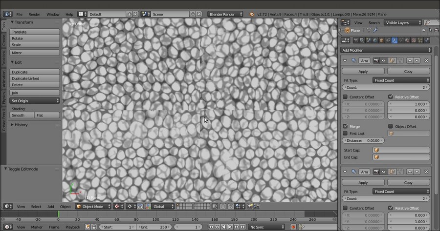
The visible seams at the borders of the Plane instances
At this point, the file is ready and we can start to paint on the image to make it tileable:
- Click on the mode button (Sets the object interaction mode) on the viewport toolbar to select the Texture Paint mode item.
- Put the mouse cursor on a bright value in the scales image and press the S key to sample it, then go near the color selector in the Brush subpanel under the Tool Shelf to the left and click on the Toggle foreground and background brush colors button (the one with the two opposing arrows) to switch the active color. Otherwise, simply press the X key, put the mouse cursor on a dark area, and press S again to sample it as the opposite color.

Sampling the light and dark colors of the image
- Set the brush's Radius and Strength values, and if you are using a graphic tablet, be sure to have the two tablet pressure sensitivity buttons at the sides of the previous items enabled.
- Start to paint by fixing the scales on the image at the seams areas. Because we can also paint on the Planes duplicated by the Array modifier, and because we are always painting on the same instanced image, it's quite simple to visually join the scales at the four sides, actually making the image tileable:

Painting on the image at the borders to make the scales seamless
It's enough to fix the areas along the middle horizontal and vertical axes of the Planes to cover all the four edges (in fact, fixing two edges is automatically fixing four).
- When you are done, go back into Object Mode and open a new window with UV/Image Editor; press Tab to go into Edit Mode, make the revised image appear, and save it (by clicking on Image | Save as Image in the toolbar or simply press the F3 key) in the
textures_makingfolder asscales_tiles.png:
Saving the tileable scales image with a different name
- Save the file as
4886OS_10_scales_tiles_02.blend.
You might wonder why we didn't use the Make Seamless filter of Gimp (Filters | Map | Make Seamless) to obtain a tileable image in one click; well, the answer is simple: the Make Seamless plugin actually offsets and blends together whole areas of the image, and this can work in several cases, but not for a complex pattern made by scales, where a simple fading is not good enough. In this case, I prefer to paint the joining line between them by hand.
Getting ready
We are taking for granted that in your Blender User Preferences window, you still have the Import Images as Planes addon enabled; if not, start Blender and just enable it as already explained in Chapter 1, Modeling the Character's Base Mesh. Then, follow these steps:
- Select and delete the default Cube primitive in the scene. Select the Camera and the Lamp and move them to the 6th scene layer.
- Click on the main File menu and then on the Import item; select the Images as Plane item.
- Browse to the
textures_makingfolder and select the providedscales.pngimage texture, which is a gray painted scales image:The "scales.png" image provided with this cookbook
- Press the period (.) key on the numpad to center the view on the selected Plane and then the 7 key on the numpad to switch to the Top Ortho view.
- Go to the Object Modifiers window and assign an Array modifier to the Plane; check the Merge item and leave all the other settings as they are.
- Click on the Copy button to assign a new identical Array modifier, and in the new Array modifier, under the Relative Offset item, change X to 0.000 and Y to 1.000.
- Save the file as
4886OS_10_scales_tiles_01.blend. - Press the period (.) key again on the numpad to center the view on the enlarged Plane, then switch the Viewport Shading mode to Texture (Alt + Z):
The UV mapped Plane with the Array modifiers assigned
As you can see in the preceding screenshot, the mapped Plane is now repeated 4 times.
By zooming towards the middle seams, it's clear that the mapped scales image is not tileable yet:
The visible seams at the borders of the Plane instances
At this point, the file is ready and we can start to paint on the image to make it tileable:
- Click on the mode button (Sets the object interaction mode) on the viewport toolbar to select the Texture Paint mode item.
- Put the mouse cursor on a bright value in the scales image and press the S key to sample it, then go near the color selector in the Brush subpanel under the Tool Shelf to the left and click on the Toggle foreground and background brush colors button (the one with the two opposing arrows) to switch the active color. Otherwise, simply press the X key, put the mouse cursor on a dark area, and press S again to sample it as the opposite color.
Sampling the light and dark colors of the image
- Set the brush's Radius and Strength values, and if you are using a graphic tablet, be sure to have the two tablet pressure sensitivity buttons at the sides of the previous items enabled.
- Start to paint by fixing the scales on the image at the seams areas. Because we can also paint on the Planes duplicated by the Array modifier, and because we are always painting on the same instanced image, it's quite simple to visually join the scales at the four sides, actually making the image tileable:
Painting on the image at the borders to make the scales seamless
It's enough to fix the areas along the middle horizontal and vertical axes of the Planes to cover all the four edges (in fact, fixing two edges is automatically fixing four).
- When you are done, go back into Object Mode and open a new window with UV/Image Editor; press Tab to go into Edit Mode, make the revised image appear, and save it (by clicking on Image | Save as Image in the toolbar or simply press the F3 key) in the
textures_makingfolder asscales_tiles.png:Saving the tileable scales image with a different name
- Save the file as
4886OS_10_scales_tiles_02.blend.
You might wonder why we didn't use the Make Seamless filter of Gimp (Filters | Map | Make Seamless) to obtain a tileable image in one click; well, the answer is simple: the Make Seamless plugin actually offsets and blends together whole areas of the image, and this can work in several cases, but not for a complex pattern made by scales, where a simple fading is not good enough. In this case, I prefer to paint the joining line between them by hand.
How to do it…
At this point, the file is ready and we can start to paint on the image to make it tileable:
- Click on the mode button (Sets the object interaction mode) on the viewport toolbar to select the Texture Paint mode item.
- Put the mouse cursor on a bright value in the scales image and press the S key to sample it, then go near the color selector in the Brush subpanel under the Tool Shelf to the left and click on the Toggle foreground and background brush colors button (the one with the two opposing arrows) to switch the active color. Otherwise, simply press the X key, put the mouse cursor on a dark area, and press S again to sample it as the opposite color.
Sampling the light and dark colors of the image
- Set the brush's Radius and Strength values, and if you are using a graphic tablet, be sure to have the two tablet pressure sensitivity buttons at the sides of the previous items enabled.
- Start to paint by fixing the scales on the image at the seams areas. Because we can also paint on the Planes duplicated by the Array modifier, and because we are always painting on the same instanced image, it's quite simple to visually join the scales at the four sides, actually making the image tileable:
Painting on the image at the borders to make the scales seamless
It's enough to fix the areas along the middle horizontal and vertical axes of the Planes to cover all the four edges (in fact, fixing two edges is automatically fixing four).
- When you are done, go back into Object Mode and open a new window with UV/Image Editor; press Tab to go into Edit Mode, make the revised image appear, and save it (by clicking on Image | Save as Image in the toolbar or simply press the F3 key) in the
textures_makingfolder asscales_tiles.png:Saving the tileable scales image with a different name
- Save the file as
4886OS_10_scales_tiles_02.blend.
You might wonder why we didn't use the Make Seamless filter of Gimp (Filters | Map | Make Seamless) to obtain a tileable image in one click; well, the answer is simple: the Make Seamless plugin actually offsets and blends together whole areas of the image, and this can work in several cases, but not for a complex pattern made by scales, where a simple fading is not good enough. In this case, I prefer to paint the joining line between them by hand.
How it works…
You might wonder why we didn't use the Make Seamless filter of Gimp (Filters | Map | Make Seamless) to obtain a tileable image in one click; well, the answer is simple: the Make Seamless plugin actually offsets and blends together whole areas of the image, and this can work in several cases, but not for a complex pattern made by scales, where a simple fading is not good enough. In this case, I prefer to paint the joining line between them by hand.
In the previous recipe, we made the scales image texture seamless, ready to be seamlessly mapped on our model. If you go back to Chapter 5, Unwrapping the Low Resolution Mesh, you'll remember that we assigned two different sets of UV coordinate layers to it: the UVMap layer, divided into 5 different tiles (this is called UDIM UV Mapping; it's a popular standard in the industry and means U-Dimension), and the UVMap_scales layer, set up to repeat the scales_tiles.png image pattern at the right size on the model:
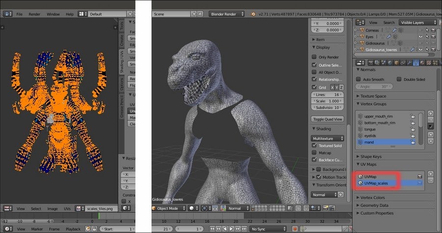
The two UV coordinates layers in the UV Maps subpanel
By zooming in and looking carefully at the result of the tiling (in Textured Solid mode, which is enabled under the Shading subpanel of the N viewport sidepanel), you can see that although we used a tileable scales image, we still have seams in some areas. This is obviously due to the fact that the UVMap_scales layer (as you can see in UV/Image Editor in the Edit Mode after selecting all the mesh's vertices) is made up of separated and overlapping islands to obtain a randomly distributed mapping of the scales on the Gidiosaurus skin:
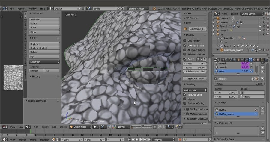
The seams on the Gidiosaurus scales skin
A simple solution to fix these seams is to bake the random scales pattern on the 5 tiles of the UVMap layer and then use the Paint Tool to adjust the gaps. This a step that we have to do in any case to allow further texture modifications such as the painting of befitting facial scales around the eyebrows, the eyes, the nostrils, and so on, but let's go in order.
To be able to bake and then paint on the different tiles in real time through the 3D viewport, we must prepare the file a bit.
Start Blender and open the Gidiosaurus_library.blend file; save it as Gidiosaurus_baking_scales_01.blend:
- Shift-click on the 13th scene layer to disable it and hide the Armor object, then enable the 6th scene layer to show Camera and Lamp. Split the 3D view into two windows and change the left one into a UV/Image Editor window (if it shows the Render Result image datablock, just click on the X icon button to unlink it).
- Put the mouse in the 3D viewport and press the T key to hide the Tool Shelf panel, and then maximize the UV/Image Editor window as much as possible. Go to the Outliner and click on the eye icon to the side of the Camera item to disable its visibility in the viewport.
- Go to the UV Maps subpanel under the Object Data window and be sure to have the UVMap layer selected (the one with the 5 different space tiles); if necessary, click on the camera icon to the right to enable it as the active UV coordinates layer.
Now, let's prepare the materials; remember that, at the moment, we are under the Blender Render engine and not under Cycles:
- Go to the Material window and out of Edit Mode, click on the – icon button to the right of the materials datablock window (Remove the selected material slot) to unlink both the
Enameland theBodymaterial datablocks. - Now click on the + icon button to add 5 material slots, and then add 5 materials by selecting each slot and clicking on the New button.
- Starting from the top one, rename the 5 materials as
Material_U0V0,Material_U1V0,Material_U2V0,Material_U0V1, andMaterial_U1V1.
Adding the 5 materials to the Gidiosaurus object
- Select the
Material U0V0slot and go to the Textures window to click on the New button and add a texture. - Scroll down the vertical panel by rotating the middle mouse wheel and click on the New button under the Image subpanel; in the New Image pop-up panel, click on the Color slot to set the Alpha (A) value to 0.000, then Ctrl + click on the Width slot and right after the default value of 1024, type
*3, then press Enter (in Blender, you can do a math calculation for any parameter like this anywhere). Copy and paste (Ctrl + C and Ctrl + V) the result of the multiplication, 3072, into the Height slot; click on the Name slot to write the texture name asblank_U0V0, then press the OK button at the bottom of the panel:
Adding a blank image texture to the first material
This adds a blank (alpha background) 3072 x 3072 pixels image as a texture on the material.
- Ctrl + left-click on the Unique datablock ID name slot right above the Type (Image or Movie) slot, and rename the default Texture name as
U0V0. Go down to the Mapping subpanel and click on the Map slot to select the UVMap item:
The "Unique datablock ID name" slot, the Image subpanel, and the Mapping subpanel
- Go to the UV/Image Editor to the left side of the screen and click on the double arrows to the side of the New button in the toolbar; from the pop-up menu select the blank_U0V0 item. Slide the toolbar to the right and click on the Image item. In the pop-up menu, select the Save as Image item (or press the F3 key) and save the image in the
texture_makingfolder asblank_U0V0.png, then click on the pin icon button to the right to activate it (Display current image regardless of object selection):
The assigned blank image loaded in the UV/Image Editor window and pinned to be displayed regardless of the object selection
As the image is saved under the Image subpanel, the Source slot caption changes from Generated to Single Image.
- Repeat the procedure for all the remaining four materials, assigning and saving a blank image texture for each material. So inside the
texture_makingfolder, you have saved the images:blank_U0V0,blank_U1V0,blank_U2V0,blank_U0V1, andblank_U1V1. - Start to split the UV/Image Editor window until you have 5 UV/Image Editor windows. Press the Tab key to go into Edit Mode with the mesh; put the mouse in the 3D viewport and press the A key to select all the mesh's vertices and therefore show the UV islands in all the UV/Image Editor windows.
- Enlarge one UV/Image Editor window as much as possible and enable the Keep UV and edit mode mesh selection in sync button on the toolbar.
- If it's the case, deselect everything, then box-select the islands (B key then left-click and drag the mouse) in the U1V0 tile space. In the Material window, select the
Material_U1V0slot and click on the Assign button. Go to the top right UV/Image Editor window and click on the X icon button on the toolbar to unlink the current image datablock (which is still blank_U0V0). Then click on the Image item on the toolbar and from the drop-down list, select theblank_U1V0image. - Press the A key to deselect everything and box-select the islands in the U2V0 tile; select the
Material_U2V0slot and again click on the Assign button. Go to the following image editor and unlink the current image datablock to load theblank_U2V0image. - Repeat for the other two missing tiles and material slots (note that this is not necessary for the U0V0 ones, which are, by default, first assigned to the whole mesh and the first created material and so still remain associated to
Material_U0V0). Then go out of Edit Mode.
The work-space prepared with the 5 UV/Image Editor windows with their respective blank images
As you can see, by selecting the vertices of the UV islands in UV/Image Editor, the corresponding vertices on the mesh are also selected. Moreover, this makes all the UV islands visible in the image editor, even though, we haven't selected a single vertex on the mesh yet (normally, you see only the islands of the selected vertices in the image editor). This way, it's simple to associate a certain UV island with a certain material and a certain group of vertices on the mesh.
- Go to the Material window and select the
Material_U0V0slot. Go to the Texture window and click on the second texture slot right under the U0V0 one. Click on the New button, scroll down to the Image subpanel, and click on the Open button to browse to thetexture_makingfolder and load thescales_tiles.pngimage. - Go to the Mapping subpanel and in the Map slot, select the UVMap_scales UV coordinates layer. Rename the
Unique datablock ID nameslot asscales_tiles. Click on the checkbox to the side of the U0V0 texture slot to disable it (this is just temporary but mandatory for the baking, otherwise it would create a dependency loop, that is, the Circular reference in texture stack message in the top main header and in the Terminal panel as well):
Disabling the blank texture image and loading the "scales_tiles.png" image in the first material
- Click on the button with a black arrow pointing downward, right after the + and –icon buttons, and from the pop-up menu, select the Copy Texture Slot Setting item. Select the
Material_U1V0slot and then click on the second texture slot right under the U1V0 one and click on the New button. Click again on the black arrow button and this time, select Paste Texture Slot Setting:
Copying and pasting the "scales_tiles" texture slot to the other materials
- Repeat this copy and paste for the other three materials, and also remember to disable the first texture slot for all the materials.
- Press Tab to go out of the Edit Mode and save the file.
Thanks to the pin icon button that is enabled for each loaded image, it's possible to keep the different images visible at the same time. At this moment, the 5 different PNG images are blank, so this isn't particularly evident; it will be a lot more clear when we start to actually paint on the model through the 3D viewport.
Getting ready
Start Blender and open the Gidiosaurus_library.blend file; save it as Gidiosaurus_baking_scales_01.blend:
- Shift-click on the 13th scene layer to disable it and hide the Armor object, then enable the 6th scene layer to show Camera and Lamp. Split the 3D view into two windows and change the left one into a UV/Image Editor window (if it shows the Render Result image datablock, just click on the X icon button to unlink it).
- Put the mouse in the 3D viewport and press the T key to hide the Tool Shelf panel, and then maximize the UV/Image Editor window as much as possible. Go to the Outliner and click on the eye icon to the side of the Camera item to disable its visibility in the viewport.
- Go to the UV Maps subpanel under the Object Data window and be sure to have the UVMap layer selected (the one with the 5 different space tiles); if necessary, click on the camera icon to the right to enable it as the active UV coordinates layer.
Now, let's prepare the materials; remember that, at the moment, we are under the Blender Render engine and not under Cycles:
- Go to the Material window and out of Edit Mode, click on the – icon button to the right of the materials datablock window (Remove the selected material slot) to unlink both the
Enameland theBodymaterial datablocks. - Now click on the + icon button to add 5 material slots, and then add 5 materials by selecting each slot and clicking on the New button.
- Starting from the top one, rename the 5 materials as
Material_U0V0,Material_U1V0,Material_U2V0,Material_U0V1, andMaterial_U1V1.Adding the 5 materials to the Gidiosaurus object
- Select the
Material U0V0slot and go to the Textures window to click on the New button and add a texture. - Scroll down the vertical panel by rotating the middle mouse wheel and click on the New button under the Image subpanel; in the New Image pop-up panel, click on the Color slot to set the Alpha (A) value to 0.000, then Ctrl + click on the Width slot and right after the default value of 1024, type
*3, then press Enter (in Blender, you can do a math calculation for any parameter like this anywhere). Copy and paste (Ctrl + C and Ctrl + V) the result of the multiplication, 3072, into the Height slot; click on the Name slot to write the texture name asblank_U0V0, then press the OK button at the bottom of the panel:Adding a blank image texture to the first material
This adds a blank (alpha background) 3072 x 3072 pixels image as a texture on the material.
- Ctrl + left-click on the Unique datablock ID name slot right above the Type (Image or Movie) slot, and rename the default Texture name as
U0V0. Go down to the Mapping subpanel and click on the Map slot to select the UVMap item:The "Unique datablock ID name" slot, the Image subpanel, and the Mapping subpanel
- Go to the UV/Image Editor to the left side of the screen and click on the double arrows to the side of the New button in the toolbar; from the pop-up menu select the blank_U0V0 item. Slide the toolbar to the right and click on the Image item. In the pop-up menu, select the Save as Image item (or press the F3 key) and save the image in the
texture_makingfolder asblank_U0V0.png, then click on the pin icon button to the right to activate it (Display current image regardless of object selection):The assigned blank image loaded in the UV/Image Editor window and pinned to be displayed regardless of the object selection
As the image is saved under the Image subpanel, the Source slot caption changes from Generated to Single Image.
- Repeat the procedure for all the remaining four materials, assigning and saving a blank image texture for each material. So inside the
texture_makingfolder, you have saved the images:blank_U0V0,blank_U1V0,blank_U2V0,blank_U0V1, andblank_U1V1. - Start to split the UV/Image Editor window until you have 5 UV/Image Editor windows. Press the Tab key to go into Edit Mode with the mesh; put the mouse in the 3D viewport and press the A key to select all the mesh's vertices and therefore show the UV islands in all the UV/Image Editor windows.
- Enlarge one UV/Image Editor window as much as possible and enable the Keep UV and edit mode mesh selection in sync button on the toolbar.
- If it's the case, deselect everything, then box-select the islands (B key then left-click and drag the mouse) in the U1V0 tile space. In the Material window, select the
Material_U1V0slot and click on the Assign button. Go to the top right UV/Image Editor window and click on the X icon button on the toolbar to unlink the current image datablock (which is still blank_U0V0). Then click on the Image item on the toolbar and from the drop-down list, select theblank_U1V0image. - Press the A key to deselect everything and box-select the islands in the U2V0 tile; select the
Material_U2V0slot and again click on the Assign button. Go to the following image editor and unlink the current image datablock to load theblank_U2V0image. - Repeat for the other two missing tiles and material slots (note that this is not necessary for the U0V0 ones, which are, by default, first assigned to the whole mesh and the first created material and so still remain associated to
Material_U0V0). Then go out of Edit Mode.The work-space prepared with the 5 UV/Image Editor windows with their respective blank images
As you can see, by selecting the vertices of the UV islands in UV/Image Editor, the corresponding vertices on the mesh are also selected. Moreover, this makes all the UV islands visible in the image editor, even though, we haven't selected a single vertex on the mesh yet (normally, you see only the islands of the selected vertices in the image editor). This way, it's simple to associate a certain UV island with a certain material and a certain group of vertices on the mesh.
- Go to the Material window and select the
Material_U0V0slot. Go to the Texture window and click on the second texture slot right under the U0V0 one. Click on the New button, scroll down to the Image subpanel, and click on the Open button to browse to thetexture_makingfolder and load thescales_tiles.pngimage. - Go to the Mapping subpanel and in the Map slot, select the UVMap_scales UV coordinates layer. Rename the
Unique datablock ID nameslot asscales_tiles. Click on the checkbox to the side of the U0V0 texture slot to disable it (this is just temporary but mandatory for the baking, otherwise it would create a dependency loop, that is, the Circular reference in texture stack message in the top main header and in the Terminal panel as well):Disabling the blank texture image and loading the "scales_tiles.png" image in the first material
- Click on the button with a black arrow pointing downward, right after the + and –icon buttons, and from the pop-up menu, select the Copy Texture Slot Setting item. Select the
Material_U1V0slot and then click on the second texture slot right under the U1V0 one and click on the New button. Click again on the black arrow button and this time, select Paste Texture Slot Setting:Copying and pasting the "scales_tiles" texture slot to the other materials
- Repeat this copy and paste for the other three materials, and also remember to disable the first texture slot for all the materials.
- Press Tab to go out of the Edit Mode and save the file.
Thanks to the pin icon button that is enabled for each loaded image, it's possible to keep the different images visible at the same time. At this moment, the 5 different PNG images are blank, so this isn't particularly evident; it will be a lot more clear when we start to actually paint on the model through the 3D viewport.
How to do it…
Now, let's prepare the materials; remember that, at the moment, we are under the Blender Render engine and not under Cycles:
- Go to the Material window and out of Edit Mode, click on the – icon button to the right of the materials datablock window (Remove the selected material slot) to unlink both the
Enameland theBodymaterial datablocks. - Now click on the + icon button to add 5 material slots, and then add 5 materials by selecting each slot and clicking on the New button.
- Starting from the top one, rename the 5 materials as
Material_U0V0,Material_U1V0,Material_U2V0,Material_U0V1, andMaterial_U1V1.Adding the 5 materials to the Gidiosaurus object
- Select the
Material U0V0slot and go to the Textures window to click on the New button and add a texture. - Scroll down the vertical panel by rotating the middle mouse wheel and click on the New button under the Image subpanel; in the New Image pop-up panel, click on the Color slot to set the Alpha (A) value to 0.000, then Ctrl + click on the Width slot and right after the default value of 1024, type
*3, then press Enter (in Blender, you can do a math calculation for any parameter like this anywhere). Copy and paste (Ctrl + C and Ctrl + V) the result of the multiplication, 3072, into the Height slot; click on the Name slot to write the texture name asblank_U0V0, then press the OK button at the bottom of the panel:Adding a blank image texture to the first material
This adds a blank (alpha background) 3072 x 3072 pixels image as a texture on the material.
- Ctrl + left-click on the Unique datablock ID name slot right above the Type (Image or Movie) slot, and rename the default Texture name as
U0V0. Go down to the Mapping subpanel and click on the Map slot to select the UVMap item:The "Unique datablock ID name" slot, the Image subpanel, and the Mapping subpanel
- Go to the UV/Image Editor to the left side of the screen and click on the double arrows to the side of the New button in the toolbar; from the pop-up menu select the blank_U0V0 item. Slide the toolbar to the right and click on the Image item. In the pop-up menu, select the Save as Image item (or press the F3 key) and save the image in the
texture_makingfolder asblank_U0V0.png, then click on the pin icon button to the right to activate it (Display current image regardless of object selection):The assigned blank image loaded in the UV/Image Editor window and pinned to be displayed regardless of the object selection
As the image is saved under the Image subpanel, the Source slot caption changes from Generated to Single Image.
- Repeat the procedure for all the remaining four materials, assigning and saving a blank image texture for each material. So inside the
texture_makingfolder, you have saved the images:blank_U0V0,blank_U1V0,blank_U2V0,blank_U0V1, andblank_U1V1. - Start to split the UV/Image Editor window until you have 5 UV/Image Editor windows. Press the Tab key to go into Edit Mode with the mesh; put the mouse in the 3D viewport and press the A key to select all the mesh's vertices and therefore show the UV islands in all the UV/Image Editor windows.
- Enlarge one UV/Image Editor window as much as possible and enable the Keep UV and edit mode mesh selection in sync button on the toolbar.
- If it's the case, deselect everything, then box-select the islands (B key then left-click and drag the mouse) in the U1V0 tile space. In the Material window, select the
Material_U1V0slot and click on the Assign button. Go to the top right UV/Image Editor window and click on the X icon button on the toolbar to unlink the current image datablock (which is still blank_U0V0). Then click on the Image item on the toolbar and from the drop-down list, select theblank_U1V0image. - Press the A key to deselect everything and box-select the islands in the U2V0 tile; select the
Material_U2V0slot and again click on the Assign button. Go to the following image editor and unlink the current image datablock to load theblank_U2V0image. - Repeat for the other two missing tiles and material slots (note that this is not necessary for the U0V0 ones, which are, by default, first assigned to the whole mesh and the first created material and so still remain associated to
Material_U0V0). Then go out of Edit Mode.The work-space prepared with the 5 UV/Image Editor windows with their respective blank images
As you can see, by selecting the vertices of the UV islands in UV/Image Editor, the corresponding vertices on the mesh are also selected. Moreover, this makes all the UV islands visible in the image editor, even though, we haven't selected a single vertex on the mesh yet (normally, you see only the islands of the selected vertices in the image editor). This way, it's simple to associate a certain UV island with a certain material and a certain group of vertices on the mesh.
- Go to the Material window and select the
Material_U0V0slot. Go to the Texture window and click on the second texture slot right under the U0V0 one. Click on the New button, scroll down to the Image subpanel, and click on the Open button to browse to thetexture_makingfolder and load thescales_tiles.pngimage. - Go to the Mapping subpanel and in the Map slot, select the UVMap_scales UV coordinates layer. Rename the
Unique datablock ID nameslot asscales_tiles. Click on the checkbox to the side of the U0V0 texture slot to disable it (this is just temporary but mandatory for the baking, otherwise it would create a dependency loop, that is, the Circular reference in texture stack message in the top main header and in the Terminal panel as well):Disabling the blank texture image and loading the "scales_tiles.png" image in the first material
- Click on the button with a black arrow pointing downward, right after the + and –icon buttons, and from the pop-up menu, select the Copy Texture Slot Setting item. Select the
Material_U1V0slot and then click on the second texture slot right under the U1V0 one and click on the New button. Click again on the black arrow button and this time, select Paste Texture Slot Setting:Copying and pasting the "scales_tiles" texture slot to the other materials
- Repeat this copy and paste for the other three materials, and also remember to disable the first texture slot for all the materials.
- Press Tab to go out of the Edit Mode and save the file.
Thanks to the pin icon button that is enabled for each loaded image, it's possible to keep the different images visible at the same time. At this moment, the 5 different PNG images are blank, so this isn't particularly evident; it will be a lot more clear when we start to actually paint on the model through the 3D viewport.
How it works…
Thanks to the pin icon button that is enabled for each loaded image, it's possible to keep the different images visible at the same time. At this moment, the 5 different PNG images are blank, so this isn't particularly evident; it will be a lot more clear when we start to actually paint on the model through the 3D viewport.
What we have to do now is to bake the scales_tiles.png image map (used in all the materials and mapped on the UVMap_scales coordinates layer) on the 5 tiles of the UVMap coordinates layer.
At this moment, Blender is not able to bake automatically outside of the default U0V0 tile space yet, so a bit of additional work is needed; nothing particularly difficult by the way. The steps are as follows:
- Press Tab to go into Edit Mode again and then put the mouse in the blank_U0V0 UV/Image Editor window; press the N key to call the Properties sidepanel and under the Display subpanel, check the Normalized item:

The Normalized item in the Display subpanel under the N Properties sidepanel of the UV/Image Editor window
- Press N again to hide the Properties sidepanel. Go to the UV Maps subpanel under the Object Data window and click on the + icon button to the right to add a new UV coordinates layer (UVMap.001), then rename it UVMap_temp (or whatever you prefer).
We are now going to create a new UV coordinates layer for the baking by moving all the islands in the outside tiles to the space of the default one; but before we go on, we must be sure about two things:
- In the toolbar of the blank_U0V0 image editor window, the Keep UV and edit mode mesh selection in sync button must now be disabled
- In the pop-up menu, accessible by clicking on the UVs item in the image editor toolbar, the Constrain to Image Bounds item must be deselected:

The "Keep UV and edit mode mesh selection in sync" button and the Constrain to Image Bounds item
Go to the blank_U0V0 image editor window; if you prefer, maximize it (mouse cursor into the window and press Ctrl + Up Arrow). If necessary, press A to deselect all the islands.
- Now, box-select the islands on the U1V0 tile, and move them to the default U0V0 tile space (G | X | -1 | Enter):

The UV islands of the U1V0 tile space, box-selected and moved to the default U0V0 tile space
- Deselect everything and box-select the islands at U2V0, then move them to the default space, which is the same as the previous one (G | X | -2 | Enter).
- Repeat for the last 2 islands tiles (G | Y | -1 | Enter) and (G | X | -1 | Enter and then G | Y | -1 | Enter), then rearrange the image editor windows.
- Go to the Object Data window and in the UV Maps subpanel, be sure to have the UVMap_temp layer, the last one, enabled as the active one, that is, the camera icon to the right side of the UVMap_temp item must be the one enabled and visible (Set the map active for rendering):

The new UVMap_temp coordinates layer
- Out of Edit Mode, go to the Render window and then go to the Bake subpanel (usually at the bottom of the panel). If necessary, click on the Bake Mode slot to select Textures, then set the Margin value to 8 or higher; and check the Clear item flag. Be sure to have the Gidiosaurus object still selected and press the Bake button.
After a while, the baked scales textures appear on the 5 PNG images, baked according to the UV islands of the 5 tiles of the UVMap layer:

The 5 baked images and the Bake subpanel under the Render window
- Click on the Image item on the UV/Image Editor toolbar and from the pop-up menu, select the Save All Images item or if you want to preserve your blank images (we are going to use them again later), just save each image at a time (Save As Image item or F3 key) with the names
baked_U0V0.png,baked_U1V0.png, and so on:
Saving the baked image maps
Opening the texture_making folder on your desktop, you will now find the baked textures:
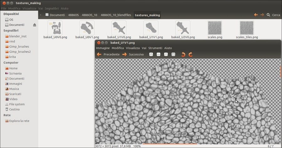
The baked textures saved inside the "texture_making" folder
As you can see in the information bar at the bottom of the GNOME image viewer (I'm working in Linux Ubuntu), each image saved from Blender is 37.8 megabytes.
The large size of the images can of course be reduced (a lot) by opening them in Gimp (or any other 2D application) and re-saving.
All the UV islands have been moved to the default U0V0 tile space, which is the only one where the baking happens, but because each image is associated with a different part of the mesh, each image is correctly baked with the right islands and textures.
In fact, inside Blender, and in our case, the location of each tile in the UV space doesn't actually matter; we made a new UV coordinates layer and kept the old one just in case the model should be exported to a different 3D application.
To move the islands exactly by the correct number of pixels, we enabled the Normalized item in the Display subpanel of the image editor N sidepanel to display the UV coordinates from 0.0 to 1.0, rather than in pixels. Anyway, without the Normalized item enabled, it would have been enough to move the islands by 3072 pixels, that is, the width (or/and height) in pixels of the assigned blank image.
As with any other software, Blender is not free from bugs; particularly, the baking section seems to have an annoying bug, which is very difficult to fix because it happens very rarely and randomly, so that it cannot easily be reproduced and consequently submitted to the Blender bug tracker (https://developer.blender.org/maniphest/project/2/type/Bug/).
It's difficult to understand the reason for this, but sometimes the software refuses to do the baking, claiming that No objects or images (are) found to bake to (the message appears on the top right main header and in the Terminal panel as well); in our case, this seems to happen when you switch the active for rendering UV coordinates layers.
If this happens, one thing you can do is check that all the images assigned in the UV/Image Editor windows to the different materials under one UV layer, also appear correctly assigned under the other UV layer (it shouldn't make a difference, but who knows), eventually re-assigning them one at a time.
If the baking still fails, there is a simple workaround; switch to the UVMap coordinates layer instead, rather than the UVMap_temp one, and just move the islands to the default U0V0 space and bake them one at a time. To do this, first bake the islands of the U0V0 tile space and save the image, then move the islands of the U1V0 tile space to the U0V0 tile space, bake and save as a different image, and so on with the islands of all the tiles.
Getting ready
At this moment, Blender is not able to bake automatically outside of the default U0V0 tile space yet, so a bit of additional work is needed; nothing particularly difficult by the way. The steps are as follows:
- Press Tab to go into Edit Mode again and then put the mouse in the blank_U0V0 UV/Image Editor window; press the N key to call the Properties sidepanel and under the Display subpanel, check the Normalized item:
The Normalized item in the Display subpanel under the N Properties sidepanel of the UV/Image Editor window
- Press N again to hide the Properties sidepanel. Go to the UV Maps subpanel under the Object Data window and click on the + icon button to the right to add a new UV coordinates layer (UVMap.001), then rename it UVMap_temp (or whatever you prefer).
We are now going to create a new UV coordinates layer for the baking by moving all the islands in the outside tiles to the space of the default one; but before we go on, we must be sure about two things:
- In the toolbar of the blank_U0V0 image editor window, the Keep UV and edit mode mesh selection in sync button must now be disabled
- In the pop-up menu, accessible by clicking on the UVs item in the image editor toolbar, the Constrain to Image Bounds item must be deselected:
The "Keep UV and edit mode mesh selection in sync" button and the Constrain to Image Bounds item
Go to the blank_U0V0 image editor window; if you prefer, maximize it (mouse cursor into the window and press Ctrl + Up Arrow). If necessary, press A to deselect all the islands.
- Now, box-select the islands on the U1V0 tile, and move them to the default U0V0 tile space (G | X | -1 | Enter):
The UV islands of the U1V0 tile space, box-selected and moved to the default U0V0 tile space
- Deselect everything and box-select the islands at U2V0, then move them to the default space, which is the same as the previous one (G | X | -2 | Enter).
- Repeat for the last 2 islands tiles (G | Y | -1 | Enter) and (G | X | -1 | Enter and then G | Y | -1 | Enter), then rearrange the image editor windows.
- Go to the Object Data window and in the UV Maps subpanel, be sure to have the UVMap_temp layer, the last one, enabled as the active one, that is, the camera icon to the right side of the UVMap_temp item must be the one enabled and visible (Set the map active for rendering):
The new UVMap_temp coordinates layer
- Out of Edit Mode, go to the Render window and then go to the Bake subpanel (usually at the bottom of the panel). If necessary, click on the Bake Mode slot to select Textures, then set the Margin value to 8 or higher; and check the Clear item flag. Be sure to have the Gidiosaurus object still selected and press the Bake button.
After a while, the baked scales textures appear on the 5 PNG images, baked according to the UV islands of the 5 tiles of the UVMap layer:
The 5 baked images and the Bake subpanel under the Render window
- Click on the Image item on the UV/Image Editor toolbar and from the pop-up menu, select the Save All Images item or if you want to preserve your blank images (we are going to use them again later), just save each image at a time (Save As Image item or F3 key) with the names
baked_U0V0.png,baked_U1V0.png, and so on:Saving the baked image maps
Opening the texture_making folder on your desktop, you will now find the baked textures:
The baked textures saved inside the "texture_making" folder
As you can see in the information bar at the bottom of the GNOME image viewer (I'm working in Linux Ubuntu), each image saved from Blender is 37.8 megabytes.
The large size of the images can of course be reduced (a lot) by opening them in Gimp (or any other 2D application) and re-saving.
All the UV islands have been moved to the default U0V0 tile space, which is the only one where the baking happens, but because each image is associated with a different part of the mesh, each image is correctly baked with the right islands and textures.
In fact, inside Blender, and in our case, the location of each tile in the UV space doesn't actually matter; we made a new UV coordinates layer and kept the old one just in case the model should be exported to a different 3D application.
To move the islands exactly by the correct number of pixels, we enabled the Normalized item in the Display subpanel of the image editor N sidepanel to display the UV coordinates from 0.0 to 1.0, rather than in pixels. Anyway, without the Normalized item enabled, it would have been enough to move the islands by 3072 pixels, that is, the width (or/and height) in pixels of the assigned blank image.
As with any other software, Blender is not free from bugs; particularly, the baking section seems to have an annoying bug, which is very difficult to fix because it happens very rarely and randomly, so that it cannot easily be reproduced and consequently submitted to the Blender bug tracker (https://developer.blender.org/maniphest/project/2/type/Bug/).
It's difficult to understand the reason for this, but sometimes the software refuses to do the baking, claiming that No objects or images (are) found to bake to (the message appears on the top right main header and in the Terminal panel as well); in our case, this seems to happen when you switch the active for rendering UV coordinates layers.
If this happens, one thing you can do is check that all the images assigned in the UV/Image Editor windows to the different materials under one UV layer, also appear correctly assigned under the other UV layer (it shouldn't make a difference, but who knows), eventually re-assigning them one at a time.
If the baking still fails, there is a simple workaround; switch to the UVMap coordinates layer instead, rather than the UVMap_temp one, and just move the islands to the default U0V0 space and bake them one at a time. To do this, first bake the islands of the U0V0 tile space and save the image, then move the islands of the U1V0 tile space to the U0V0 tile space, bake and save as a different image, and so on with the islands of all the tiles.
How to do it…
We are now going to create a new UV coordinates layer for the baking by moving all the islands in the outside tiles to the space of the default one; but before we go on, we must be sure about two things:
- In the toolbar of the blank_U0V0 image editor window, the Keep UV and edit mode mesh selection in sync button must now be disabled
- In the pop-up menu, accessible by clicking on the UVs item in the image editor toolbar, the Constrain to Image Bounds item must be deselected:
The "Keep UV and edit mode mesh selection in sync" button and the Constrain to Image Bounds item
Go to the blank_U0V0 image editor window; if you prefer, maximize it (mouse cursor into the window and press Ctrl + Up Arrow). If necessary, press A to deselect all the islands.
- Now, box-select the islands on the U1V0 tile, and move them to the default U0V0 tile space (G | X | -1 | Enter):
The UV islands of the U1V0 tile space, box-selected and moved to the default U0V0 tile space
- Deselect everything and box-select the islands at U2V0, then move them to the default space, which is the same as the previous one (G | X | -2 | Enter).
- Repeat for the last 2 islands tiles (G | Y | -1 | Enter) and (G | X | -1 | Enter and then G | Y | -1 | Enter), then rearrange the image editor windows.
- Go to the Object Data window and in the UV Maps subpanel, be sure to have the UVMap_temp layer, the last one, enabled as the active one, that is, the camera icon to the right side of the UVMap_temp item must be the one enabled and visible (Set the map active for rendering):
The new UVMap_temp coordinates layer
- Out of Edit Mode, go to the Render window and then go to the Bake subpanel (usually at the bottom of the panel). If necessary, click on the Bake Mode slot to select Textures, then set the Margin value to 8 or higher; and check the Clear item flag. Be sure to have the Gidiosaurus object still selected and press the Bake button.
After a while, the baked scales textures appear on the 5 PNG images, baked according to the UV islands of the 5 tiles of the UVMap layer:
The 5 baked images and the Bake subpanel under the Render window
- Click on the Image item on the UV/Image Editor toolbar and from the pop-up menu, select the Save All Images item or if you want to preserve your blank images (we are going to use them again later), just save each image at a time (Save As Image item or F3 key) with the names
baked_U0V0.png,baked_U1V0.png, and so on:Saving the baked image maps
Opening the texture_making folder on your desktop, you will now find the baked textures:
The baked textures saved inside the "texture_making" folder
As you can see in the information bar at the bottom of the GNOME image viewer (I'm working in Linux Ubuntu), each image saved from Blender is 37.8 megabytes.
The large size of the images can of course be reduced (a lot) by opening them in Gimp (or any other 2D application) and re-saving.
All the UV islands have been moved to the default U0V0 tile space, which is the only one where the baking happens, but because each image is associated with a different part of the mesh, each image is correctly baked with the right islands and textures.
In fact, inside Blender, and in our case, the location of each tile in the UV space doesn't actually matter; we made a new UV coordinates layer and kept the old one just in case the model should be exported to a different 3D application.
To move the islands exactly by the correct number of pixels, we enabled the Normalized item in the Display subpanel of the image editor N sidepanel to display the UV coordinates from 0.0 to 1.0, rather than in pixels. Anyway, without the Normalized item enabled, it would have been enough to move the islands by 3072 pixels, that is, the width (or/and height) in pixels of the assigned blank image.
As with any other software, Blender is not free from bugs; particularly, the baking section seems to have an annoying bug, which is very difficult to fix because it happens very rarely and randomly, so that it cannot easily be reproduced and consequently submitted to the Blender bug tracker (https://developer.blender.org/maniphest/project/2/type/Bug/).
It's difficult to understand the reason for this, but sometimes the software refuses to do the baking, claiming that No objects or images (are) found to bake to (the message appears on the top right main header and in the Terminal panel as well); in our case, this seems to happen when you switch the active for rendering UV coordinates layers.
If this happens, one thing you can do is check that all the images assigned in the UV/Image Editor windows to the different materials under one UV layer, also appear correctly assigned under the other UV layer (it shouldn't make a difference, but who knows), eventually re-assigning them one at a time.
If the baking still fails, there is a simple workaround; switch to the UVMap coordinates layer instead, rather than the UVMap_temp one, and just move the islands to the default U0V0 space and bake them one at a time. To do this, first bake the islands of the U0V0 tile space and save the image, then move the islands of the U1V0 tile space to the U0V0 tile space, bake and save as a different image, and so on with the islands of all the tiles.
How it works…
All the UV islands have been moved to the default U0V0 tile space, which is the only one where the baking happens, but because each image is associated with a different part of the mesh, each image is correctly baked with the right islands and textures.
In fact, inside Blender, and in our case, the location of each tile in the UV space doesn't actually matter; we made a new UV coordinates layer and kept the old one just in case the model should be exported to a different 3D application.
To move the islands exactly by the correct number of pixels, we enabled the Normalized item in the Display subpanel of the image editor N sidepanel to display the UV coordinates from 0.0 to 1.0, rather than in pixels. Anyway, without the Normalized item enabled, it would have been enough to move the islands by 3072 pixels, that is, the width (or/and height) in pixels of the assigned blank image.
As with any other software, Blender is not free from bugs; particularly, the baking section seems to have an annoying bug, which is very difficult to fix because it happens very rarely and randomly, so that it cannot easily be reproduced and consequently submitted to the Blender bug tracker (https://developer.blender.org/maniphest/project/2/type/Bug/).
It's difficult to understand the reason for this, but sometimes the software refuses to do the baking, claiming that No objects or images (are) found to bake to (the message appears on the top right main header and in the Terminal panel as well); in our case, this seems to happen when you switch the active for rendering UV coordinates layers.
If this happens, one thing you can do is check that all the images assigned in the UV/Image Editor windows to the different materials under one UV layer, also appear correctly assigned under the other UV layer (it shouldn't make a difference, but who knows), eventually re-assigning them one at a time.
If the baking still fails, there is a simple workaround; switch to the UVMap coordinates layer instead, rather than the UVMap_temp one, and just move the islands to the default U0V0 space and bake them one at a time. To do this, first bake the islands of the U0V0 tile space and save the image, then move the islands of the U1V0 tile space to the U0V0 tile space, bake and save as a different image, and so on with the islands of all the tiles.
There's more…
As with any other software, Blender is not free from bugs; particularly, the baking section seems to have an annoying bug, which is very difficult to fix because it happens very rarely and randomly, so that it cannot easily be reproduced and consequently submitted to the Blender bug tracker (https://developer.blender.org/maniphest/project/2/type/Bug/).
It's difficult to understand the reason for this, but sometimes the software refuses to do the baking, claiming that No objects or images (are) found to bake to (the message appears on the top right main header and in the Terminal panel as well); in our case, this seems to happen when you switch the active for rendering UV coordinates layers.
If this happens, one thing you can do is check that all the images assigned in the UV/Image Editor windows to the different materials under one UV layer, also appear correctly assigned under the other UV layer (it shouldn't make a difference, but who knows), eventually re-assigning them one at a time.
If the baking still fails, there is a simple workaround; switch to the UVMap coordinates layer instead, rather than the UVMap_temp one, and just move the islands to the default U0V0 space and bake them one at a time. To do this, first bake the islands of the U0V0 tile space and save the image, then move the islands of the U1V0 tile space to the U0V0 tile space, bake and save as a different image, and so on with the islands of all the tiles.
In the previous recipe, we baked the randomly tiled scales image map on the 5 tiles of the UVMap coordinates layer. This was necessary for the next step to be able to fix seams and modify certain areas of the baked scales images through the Paint Tool.
In order to paint in real time on both the model and on all the images assigned to the 5 different UV tiles, and at the same time, once again we need to first prepare the file. To be more precise, we must assign 5 different materials to the mesh, one for each tile and each one with the appropriate image texture.
Start Blender and re-open the Gidiosaurus_baking_scales_01.blend file; save the file as Gidiosaurus_baking_scales_02.blend.
- Minimize the image editor windows on the left as much as possible, then also minimize the Outliner, the Material, and the Texture windows on the right to make room for the 3D viewport.
- Click on the Viewport Shading button in the 3D viewport toolbar and switch the shading mode from Material to Solid, then press the T key to call the Tool Shelf. Then switch from Object Mode to Texture Paint mode by clicking on the mode button in the toolbar:

Switching to Texture Paint mode
- Click on the Options tab inside the Tool Shelf and under the Project Paint subpanel, enable the Occlude, Null, and Normal items:

Items to be enabled under the Options tab
- Click on the Tools tab inside the Tool Shelf to go back to the Brush subpanel options.
At this point, we are ready to start to paint both directly on the model in the 3D viewport or also in the UV/Image Editor windows (just for all eventualities, I suggest you make a copy of the baked scales images before starting to paint):
- Zoom in on a part of the Gidiosaurus object in the 3D viewport, for example, the head.
- Put the mouse cursor on a bright value of the scales image on the model and press the S key to sample it, then go near the color selector in the Brush subpanel under the Tool Shelf to the left and click on the Toggle foreground and background brush colors button (the one with the two opposing arrows) to switch the active color. Otherwise, simply press the X key, put the mouse cursor on a dark area, and press S again to sample it as the opposite color.
- Scroll down and click on the New button (Add new palette) at the bottom of the Brush subpanel; + and – icon buttons will have appeared above the color switcher. Click on the + icon button to add the active color to the palette, then switch the colors and click on the + button again to add a new color to the palette.
- Set the brush's Radius value to 6 and Strength value to 1.000, and if you are using a graphic tablet, be sure to have the 2 tablet pressure sensitivity buttons at the sides of the previous items enabled. Change the default Palette name in Scales.

Setting a palette and the brush strength and radius
- Simply start to paint on the model, re-drawing the scales where there are seams by flipping the color as you need to, by pressing the X key and painting the dark folds and the light scales. The two colors we sampled, used with the pressure sensitivity enabled, should be enough, but feel free to sample new ones and add it to the palette as you go on:

Painting on the model to fix the image texture seams
- From time to time, click on the Slots tab in the Tool Shelf and click on the Save All Images button.
- Do most of the fixing you can, across the entire Gidiosaurus body, keeping in mind that it's quite useless to spend time fixing seams in areas that will later be covered by the Armor (for example, the top of the head).
- When you are done, be sure to have saved all the edited images as explained in step 6 (but you can also do it one image at a time through the Image | Save Image item in each editor window toolbar or by pressing the Alt + S shortcut).
- Now, be sure to have the
Material_U0V0slot selected as active in the Material window and go to the Texture window; left-click on the empty slot right under the U0V0 one and then click on the New button to add a new image texture. - Scroll down to the Image subpanel and click on the New button. In the New Image pop-up panel, write
added_scales_U0V0in the Name slot, then set the Width and Height values to 3072 and the Alpha (A) value to 0.000 (basically add a new blank and background transparent image as shown in step 5 of the How to do it… section of the Preparing the model to use the UDIM UV tiles recipe):
Adding a new texture paint slot layer
- Go to the Shading subpanel of the Material window and enable the Shadeless item for the
Material_U0V0slot. Then go to the 3D viewport toolbar and change Viewport Shading from Solid to Material. - If not selected already, click on the Slots tab in the Tool Shelf panel and select the
added_scales_U0V0item that appears under theU0V0.pngonce inside the Available Paint Slots window. - Directly in the 3D view, start to paint new scales on the eyebrows to replace the randomly distributed ones; use the light color of the palette to conceal the old scales on the first layer, and the dark color to draw the new ones. Try to build a consistent pattern, also using photos of real reptiles as references. When you are done, save the image in the
texture_makingfolder:
Painting new scales on the eyebrow
- Draw new scales around the nostrils and the rim of the mouth:

Painting new scales also around the nostrils and at the rim of the mouth
The Blender Paint Tool also has other handy brushes; a particularly useful one is the Smear brush, which smudges the borders or any blotch in the scales.
To access the brushes, just click on the big window in the Brush subpanel under the Tool Shelf and click on the chosen one to select it:

The brushes selection pop-up menu
Remember to always save the painted images before closing Blender, otherwise you'll lose them.
Also remember that if you have more than one texture layer to save, it's necessary to load each one of them into an UV/Image Editor window. This is actually very quick and easy, just select each layer in the Available Paint Slots window (in the Slots subpanel under the Slots tab) to make it appear in the image editor window and save it through the Image | Save As Image menu in the editor toolbar.
Once saved the first time, it's possible to re-save all of them in one single click, through the Save All Images items, both in the tab, as well as in the toolbar menu.
- Save the file as
Gidiosaurus_painting_scales_fix.blend.Note
In the textures and blend files provided with this cookbook, you'll find textures fixed only in the head area; I leave the task of finishing the fixing and drawing of new scales on the rest of the body (for example, bigger scales can be added to the upper side of the hand fingers, feet, shoulders, and so on) to you.
The new Blender 2.73 texture paint layering feature works simply by adding a new texture slot to the material, and automatically setting it as required, by the type of texture you selected in the Add Texture Paint Slot; in fact, by going to the Texture window, it is possible to see the added new texture slot and also, if necessary, to change the settings:

The added texture paint slot also appearing as a texture slot in the Texture window
Nonetheless, it is a great addition to Blender that can simplify the texture painting workflow a lot.
To bake the added scales as a single image with the background scales images, perform the following steps:
- Enter Edit Mode and click on the Select button for
Material_U0V0to select the vertices assigned to that tile. - Go to the top left UV/Image Editor window and press Alt + N to call the New Image pop-up menu; add a new blank image of 3072 x 3072 pixels named
baked_scales_U0V0, and save it inside thetextures_makingfolder. - Go out of Edit Mode and if it's the case, click on the double arrows icon to the left side of the image name datablock to re-assign the just-created
Untitledimage. - Repeat for the other four materials, naming the new images according to the tile and saving them inside the
texture_makingfolder as well. - Go to the UV Maps subpanel under the Object Data window to make the UVMap_temp coordinates layer active.
- Go to the Render window, and be sure that the Bake Mode under the Bake subpanel is set to Textures, then click on the Bake button.
- After the baking is done, click on the Image item in the toolbar of one of the image editors and select the Save All Images item.
Not necessarily everything has to be fixed by painting in Blender; for example, it would be enough to fix the scales on only the half of the head, export the painted image texture, and open it in Gimp (or any other 2D image editing software):

The scales "U0V0.png" image map and the "added_scales_U0V0.png" layer in Gimp
Then, by duplicating the layer and mirroring it, plus a little bit of painting to adjust the seams, it's really simple to obtain the missing half of the new scales texture:

The duplicated and mirrored "added_scales_U0V0.png" layer in Gimp
Of course, if you want to fix every side and part by hand-painting on the model in Blender to obtain a more natural looking result, no one is going to stop you!
Getting ready
Start Blender and re-open the Gidiosaurus_baking_scales_01.blend file; save the file as Gidiosaurus_baking_scales_02.blend.
- Minimize the image editor windows on the left as much as possible, then also minimize the Outliner, the Material, and the Texture windows on the right to make room for the 3D viewport.
- Click on the Viewport Shading button in the 3D viewport toolbar and switch the shading mode from Material to Solid, then press the T key to call the Tool Shelf. Then switch from Object Mode to Texture Paint mode by clicking on the mode button in the toolbar:
Switching to Texture Paint mode
- Click on the Options tab inside the Tool Shelf and under the Project Paint subpanel, enable the Occlude, Null, and Normal items:
Items to be enabled under the Options tab
- Click on the Tools tab inside the Tool Shelf to go back to the Brush subpanel options.
At this point, we are ready to start to paint both directly on the model in the 3D viewport or also in the UV/Image Editor windows (just for all eventualities, I suggest you make a copy of the baked scales images before starting to paint):
- Zoom in on a part of the Gidiosaurus object in the 3D viewport, for example, the head.
- Put the mouse cursor on a bright value of the scales image on the model and press the S key to sample it, then go near the color selector in the Brush subpanel under the Tool Shelf to the left and click on the Toggle foreground and background brush colors button (the one with the two opposing arrows) to switch the active color. Otherwise, simply press the X key, put the mouse cursor on a dark area, and press S again to sample it as the opposite color.
- Scroll down and click on the New button (Add new palette) at the bottom of the Brush subpanel; + and – icon buttons will have appeared above the color switcher. Click on the + icon button to add the active color to the palette, then switch the colors and click on the + button again to add a new color to the palette.
- Set the brush's Radius value to 6 and Strength value to 1.000, and if you are using a graphic tablet, be sure to have the 2 tablet pressure sensitivity buttons at the sides of the previous items enabled. Change the default Palette name in Scales.
Setting a palette and the brush strength and radius
- Simply start to paint on the model, re-drawing the scales where there are seams by flipping the color as you need to, by pressing the X key and painting the dark folds and the light scales. The two colors we sampled, used with the pressure sensitivity enabled, should be enough, but feel free to sample new ones and add it to the palette as you go on:
Painting on the model to fix the image texture seams
- From time to time, click on the Slots tab in the Tool Shelf and click on the Save All Images button.
- Do most of the fixing you can, across the entire Gidiosaurus body, keeping in mind that it's quite useless to spend time fixing seams in areas that will later be covered by the Armor (for example, the top of the head).
- When you are done, be sure to have saved all the edited images as explained in step 6 (but you can also do it one image at a time through the Image | Save Image item in each editor window toolbar or by pressing the Alt + S shortcut).
- Now, be sure to have the
Material_U0V0slot selected as active in the Material window and go to the Texture window; left-click on the empty slot right under the U0V0 one and then click on the New button to add a new image texture. - Scroll down to the Image subpanel and click on the New button. In the New Image pop-up panel, write
added_scales_U0V0in the Name slot, then set the Width and Height values to 3072 and the Alpha (A) value to 0.000 (basically add a new blank and background transparent image as shown in step 5 of the How to do it… section of the Preparing the model to use the UDIM UV tiles recipe):Adding a new texture paint slot layer
- Go to the Shading subpanel of the Material window and enable the Shadeless item for the
Material_U0V0slot. Then go to the 3D viewport toolbar and change Viewport Shading from Solid to Material. - If not selected already, click on the Slots tab in the Tool Shelf panel and select the
added_scales_U0V0item that appears under theU0V0.pngonce inside the Available Paint Slots window. - Directly in the 3D view, start to paint new scales on the eyebrows to replace the randomly distributed ones; use the light color of the palette to conceal the old scales on the first layer, and the dark color to draw the new ones. Try to build a consistent pattern, also using photos of real reptiles as references. When you are done, save the image in the
texture_makingfolder:Painting new scales on the eyebrow
- Draw new scales around the nostrils and the rim of the mouth:
Painting new scales also around the nostrils and at the rim of the mouth
The Blender Paint Tool also has other handy brushes; a particularly useful one is the Smear brush, which smudges the borders or any blotch in the scales.
To access the brushes, just click on the big window in the Brush subpanel under the Tool Shelf and click on the chosen one to select it:
The brushes selection pop-up menu
Remember to always save the painted images before closing Blender, otherwise you'll lose them.
Also remember that if you have more than one texture layer to save, it's necessary to load each one of them into an UV/Image Editor window. This is actually very quick and easy, just select each layer in the Available Paint Slots window (in the Slots subpanel under the Slots tab) to make it appear in the image editor window and save it through the Image | Save As Image menu in the editor toolbar.
Once saved the first time, it's possible to re-save all of them in one single click, through the Save All Images items, both in the tab, as well as in the toolbar menu.
- Save the file as
Gidiosaurus_painting_scales_fix.blend.Note
In the textures and blend files provided with this cookbook, you'll find textures fixed only in the head area; I leave the task of finishing the fixing and drawing of new scales on the rest of the body (for example, bigger scales can be added to the upper side of the hand fingers, feet, shoulders, and so on) to you.
The new Blender 2.73 texture paint layering feature works simply by adding a new texture slot to the material, and automatically setting it as required, by the type of texture you selected in the Add Texture Paint Slot; in fact, by going to the Texture window, it is possible to see the added new texture slot and also, if necessary, to change the settings:
The added texture paint slot also appearing as a texture slot in the Texture window
Nonetheless, it is a great addition to Blender that can simplify the texture painting workflow a lot.
To bake the added scales as a single image with the background scales images, perform the following steps:
- Enter Edit Mode and click on the Select button for
Material_U0V0to select the vertices assigned to that tile. - Go to the top left UV/Image Editor window and press Alt + N to call the New Image pop-up menu; add a new blank image of 3072 x 3072 pixels named
baked_scales_U0V0, and save it inside thetextures_makingfolder. - Go out of Edit Mode and if it's the case, click on the double arrows icon to the left side of the image name datablock to re-assign the just-created
Untitledimage. - Repeat for the other four materials, naming the new images according to the tile and saving them inside the
texture_makingfolder as well. - Go to the UV Maps subpanel under the Object Data window to make the UVMap_temp coordinates layer active.
- Go to the Render window, and be sure that the Bake Mode under the Bake subpanel is set to Textures, then click on the Bake button.
- After the baking is done, click on the Image item in the toolbar of one of the image editors and select the Save All Images item.
Not necessarily everything has to be fixed by painting in Blender; for example, it would be enough to fix the scales on only the half of the head, export the painted image texture, and open it in Gimp (or any other 2D image editing software):
The scales "U0V0.png" image map and the "added_scales_U0V0.png" layer in Gimp
Then, by duplicating the layer and mirroring it, plus a little bit of painting to adjust the seams, it's really simple to obtain the missing half of the new scales texture:
The duplicated and mirrored "added_scales_U0V0.png" layer in Gimp
Of course, if you want to fix every side and part by hand-painting on the model in Blender to obtain a more natural looking result, no one is going to stop you!
How to do it…
At this point, we are ready to start to paint both directly on the model in the 3D viewport or also in the UV/Image Editor windows (just for all eventualities, I suggest you make a copy of the baked scales images before starting to paint):
- Zoom in on a part of the Gidiosaurus object in the 3D viewport, for example, the head.
- Put the mouse cursor on a bright value of the scales image on the model and press the S key to sample it, then go near the color selector in the Brush subpanel under the Tool Shelf to the left and click on the Toggle foreground and background brush colors button (the one with the two opposing arrows) to switch the active color. Otherwise, simply press the X key, put the mouse cursor on a dark area, and press S again to sample it as the opposite color.
- Scroll down and click on the New button (Add new palette) at the bottom of the Brush subpanel; + and – icon buttons will have appeared above the color switcher. Click on the + icon button to add the active color to the palette, then switch the colors and click on the + button again to add a new color to the palette.
- Set the brush's Radius value to 6 and Strength value to 1.000, and if you are using a graphic tablet, be sure to have the 2 tablet pressure sensitivity buttons at the sides of the previous items enabled. Change the default Palette name in Scales.
Setting a palette and the brush strength and radius
- Simply start to paint on the model, re-drawing the scales where there are seams by flipping the color as you need to, by pressing the X key and painting the dark folds and the light scales. The two colors we sampled, used with the pressure sensitivity enabled, should be enough, but feel free to sample new ones and add it to the palette as you go on:
Painting on the model to fix the image texture seams
- From time to time, click on the Slots tab in the Tool Shelf and click on the Save All Images button.
- Do most of the fixing you can, across the entire Gidiosaurus body, keeping in mind that it's quite useless to spend time fixing seams in areas that will later be covered by the Armor (for example, the top of the head).
- When you are done, be sure to have saved all the edited images as explained in step 6 (but you can also do it one image at a time through the Image | Save Image item in each editor window toolbar or by pressing the Alt + S shortcut).
- Now, be sure to have the
Material_U0V0slot selected as active in the Material window and go to the Texture window; left-click on the empty slot right under the U0V0 one and then click on the New button to add a new image texture. - Scroll down to the Image subpanel and click on the New button. In the New Image pop-up panel, write
added_scales_U0V0in the Name slot, then set the Width and Height values to 3072 and the Alpha (A) value to 0.000 (basically add a new blank and background transparent image as shown in step 5 of the How to do it… section of the Preparing the model to use the UDIM UV tiles recipe):Adding a new texture paint slot layer
- Go to the Shading subpanel of the Material window and enable the Shadeless item for the
Material_U0V0slot. Then go to the 3D viewport toolbar and change Viewport Shading from Solid to Material. - If not selected already, click on the Slots tab in the Tool Shelf panel and select the
added_scales_U0V0item that appears under theU0V0.pngonce inside the Available Paint Slots window. - Directly in the 3D view, start to paint new scales on the eyebrows to replace the randomly distributed ones; use the light color of the palette to conceal the old scales on the first layer, and the dark color to draw the new ones. Try to build a consistent pattern, also using photos of real reptiles as references. When you are done, save the image in the
texture_makingfolder:Painting new scales on the eyebrow
- Draw new scales around the nostrils and the rim of the mouth:
Painting new scales also around the nostrils and at the rim of the mouth
The Blender Paint Tool also has other handy brushes; a particularly useful one is the Smear brush, which smudges the borders or any blotch in the scales.
To access the brushes, just click on the big window in the Brush subpanel under the Tool Shelf and click on the chosen one to select it:
The brushes selection pop-up menu
Remember to always save the painted images before closing Blender, otherwise you'll lose them.
Also remember that if you have more than one texture layer to save, it's necessary to load each one of them into an UV/Image Editor window. This is actually very quick and easy, just select each layer in the Available Paint Slots window (in the Slots subpanel under the Slots tab) to make it appear in the image editor window and save it through the Image | Save As Image menu in the editor toolbar.
Once saved the first time, it's possible to re-save all of them in one single click, through the Save All Images items, both in the tab, as well as in the toolbar menu.
- Save the file as
Gidiosaurus_painting_scales_fix.blend.Note
In the textures and blend files provided with this cookbook, you'll find textures fixed only in the head area; I leave the task of finishing the fixing and drawing of new scales on the rest of the body (for example, bigger scales can be added to the upper side of the hand fingers, feet, shoulders, and so on) to you.
The new Blender 2.73 texture paint layering feature works simply by adding a new texture slot to the material, and automatically setting it as required, by the type of texture you selected in the Add Texture Paint Slot; in fact, by going to the Texture window, it is possible to see the added new texture slot and also, if necessary, to change the settings:
The added texture paint slot also appearing as a texture slot in the Texture window
Nonetheless, it is a great addition to Blender that can simplify the texture painting workflow a lot.
To bake the added scales as a single image with the background scales images, perform the following steps:
- Enter Edit Mode and click on the Select button for
Material_U0V0to select the vertices assigned to that tile. - Go to the top left UV/Image Editor window and press Alt + N to call the New Image pop-up menu; add a new blank image of 3072 x 3072 pixels named
baked_scales_U0V0, and save it inside thetextures_makingfolder. - Go out of Edit Mode and if it's the case, click on the double arrows icon to the left side of the image name datablock to re-assign the just-created
Untitledimage. - Repeat for the other four materials, naming the new images according to the tile and saving them inside the
texture_makingfolder as well. - Go to the UV Maps subpanel under the Object Data window to make the UVMap_temp coordinates layer active.
- Go to the Render window, and be sure that the Bake Mode under the Bake subpanel is set to Textures, then click on the Bake button.
- After the baking is done, click on the Image item in the toolbar of one of the image editors and select the Save All Images item.
Not necessarily everything has to be fixed by painting in Blender; for example, it would be enough to fix the scales on only the half of the head, export the painted image texture, and open it in Gimp (or any other 2D image editing software):
The scales "U0V0.png" image map and the "added_scales_U0V0.png" layer in Gimp
Then, by duplicating the layer and mirroring it, plus a little bit of painting to adjust the seams, it's really simple to obtain the missing half of the new scales texture:
The duplicated and mirrored "added_scales_U0V0.png" layer in Gimp
Of course, if you want to fix every side and part by hand-painting on the model in Blender to obtain a more natural looking result, no one is going to stop you!
How it works…
The new Blender 2.73 texture paint layering feature works simply by adding a new texture slot to the material, and automatically setting it as required, by the type of texture you selected in the Add Texture Paint Slot; in fact, by going to the Texture window, it is possible to see the added new texture slot and also, if necessary, to change the settings:
The added texture paint slot also appearing as a texture slot in the Texture window
Nonetheless, it is a great addition to Blender that can simplify the texture painting workflow a lot.
To bake the added scales as a single image with the background scales images, perform the following steps:
- Enter Edit Mode and click on the Select button for
Material_U0V0to select the vertices assigned to that tile. - Go to the top left UV/Image Editor window and press Alt + N to call the New Image pop-up menu; add a new blank image of 3072 x 3072 pixels named
baked_scales_U0V0, and save it inside thetextures_makingfolder. - Go out of Edit Mode and if it's the case, click on the double arrows icon to the left side of the image name datablock to re-assign the just-created
Untitledimage. - Repeat for the other four materials, naming the new images according to the tile and saving them inside the
texture_makingfolder as well. - Go to the UV Maps subpanel under the Object Data window to make the UVMap_temp coordinates layer active.
- Go to the Render window, and be sure that the Bake Mode under the Bake subpanel is set to Textures, then click on the Bake button.
- After the baking is done, click on the Image item in the toolbar of one of the image editors and select the Save All Images item.
Not necessarily everything has to be fixed by painting in Blender; for example, it would be enough to fix the scales on only the half of the head, export the painted image texture, and open it in Gimp (or any other 2D image editing software):
The scales "U0V0.png" image map and the "added_scales_U0V0.png" layer in Gimp
Then, by duplicating the layer and mirroring it, plus a little bit of painting to adjust the seams, it's really simple to obtain the missing half of the new scales texture:
The duplicated and mirrored "added_scales_U0V0.png" layer in Gimp
Of course, if you want to fix every side and part by hand-painting on the model in Blender to obtain a more natural looking result, no one is going to stop you!
There's more…
To bake the added scales as a single image with the background scales images, perform the following steps:
- Enter Edit Mode and click on the Select button for
Material_U0V0to select the vertices assigned to that tile. - Go to the top left UV/Image Editor window and press Alt + N to call the New Image pop-up menu; add a new blank image of 3072 x 3072 pixels named
baked_scales_U0V0, and save it inside thetextures_makingfolder. - Go out of Edit Mode and if it's the case, click on the double arrows icon to the left side of the image name datablock to re-assign the just-created
Untitledimage. - Repeat for the other four materials, naming the new images according to the tile and saving them inside the
texture_makingfolder as well. - Go to the UV Maps subpanel under the Object Data window to make the UVMap_temp coordinates layer active.
- Go to the Render window, and be sure that the Bake Mode under the Bake subpanel is set to Textures, then click on the Bake button.
- After the baking is done, click on the Image item in the toolbar of one of the image editors and select the Save All Images item.
Not necessarily everything has to be fixed by painting in Blender; for example, it would be enough to fix the scales on only the half of the head, export the painted image texture, and open it in Gimp (or any other 2D image editing software):
The scales "U0V0.png" image map and the "added_scales_U0V0.png" layer in Gimp
Then, by duplicating the layer and mirroring it, plus a little bit of painting to adjust the seams, it's really simple to obtain the missing half of the new scales texture:
The duplicated and mirrored "added_scales_U0V0.png" layer in Gimp
Of course, if you want to fix every side and part by hand-painting on the model in Blender to obtain a more natural looking result, no one is going to stop you!
After having obtained the scales textures, we must now paint the diffuse color of the Gidiosaurus character.
Start Blender and open the Gidiosaurus_baking_scales.blend file:
- Go to the main Properties panel and be sure to have the UVMap coordinates layer selected and active, in the UV Maps subpanel under the Object Data window.
- Go to the Material window and select the
Material_U0V0slot, then go to the Texture window and be sure to have the scales_tiles texture slot selected; left-click on the X icon button to the right side of the name datablock to unlink it (Shift + left-click to remove it from the file):
Unlinking the scales_tiles texture slot datablock
- Select and enable (by clicking on the checkbox to the right) the U0V0 texture slot. Repeat the procedure at steps 2 and 3 for all 5 materials.
I'll take for granted that you have preserved your blank images and that they are the ones loaded into the current file; otherwise, substitute them with new blank images (you have to do this both in the Texture window as well as in the UV/Image Editor windows) by following steps 5 and 7 of the Preparing the model to use the UDIM UV tiles recipe in this chapter.
- Minimize the image editor windows to the left and the Material and Texture panels to the right as much as possible, then click on the mode button (Sets the object interaction mode) on the toolbar to go into Texture Paint mode. Press T with the mouse pointer over the 3D view to call the Tool Shelf and click on the Viewport Shading button on the toolbar to switch to Solid mode:

Switching to Solid viewport shading mode
- Just to verify that everything works correctly, select a black color (or any other one) in the color wheel under the Brush subpanel and trace a continuous stroke in the 3D viewport that envelopes all the Gidiosaurus body parts:

Testing that everything works correctly with a single stroke on the mesh
By enlarging the UV/Image Editor windows, you will see that after the stroke, each image has been updated with the corresponding painting (pay no attention to the over-imposed and repeated for each window UV islands):

The test stroke correctly visible inside each one of the UV/Image Editor windows
- Rearrange the image editor windows, then press Ctrl + Z to undo the stroke and save the file as
Gidiosaurus_painting_BI.blend.
We are now ready to paint the basic color for the Gidiosaurus character. But first, one more little thing:
- Select the Gidiosaurus object and enter Edit Mode; select the vertices of all the teeth and all the talons, then assign a new vertex group renamed enamel; press Ctrl + I to invert the selection and go out of Edit Mode.
- Now, start by selecting a medium dark greenish color (R 0.349, G 0.510, B 0.435) in the color wheel under the Brush subpanel. Scroll down and go to the bottom of the subpanel and click on the New button to create a new palette, then click on the + icon button (Add Swatch) above the Foreground Color slot (the left one) to add the color to the palette. Rename the default Palette name as
Gidiosaurus_colors. - In the 3D viewport toolbar, click on the Face selection masking for painting button to enable the masking tool; now it's possible to paint only on the part of the mesh that has selected vertices in Edit Mode, so in this case we want to paint only on the skin, leaving the teeth and the talons blank.
- Click on the Brush window and select the Fill brush; if necessary, click on the greenish color box added to the palette (called Swatch) to load it as the foreground color (note that with the Fill brush, the background color swatch disappears and the foreground color swatch becomes the only one available). Set the Strength value to 1.000 and click on the Gidiosaurus object in the 3D viewport.
After a while, all the paintable parts of the mesh are filled with the active color (and therefore also the textures in the UV/Image Editor windows; there are weird straight lines, probably a bug, but not a problem in this case because they don't show on the mesh and we can fill in the texture's backgrounds later anyway). If any tiny part is left out, just click on one of the parts again to fill it:

The Fill brush and the Mask button in the 3D view toolbar
- Now select the TexDraw brush and a darker and more saturated green color (R 0.129, G 0.275, B 0.125) as the foreground color, and add it to the palette.
- Under the Tool Shelf, go to the Options tab and be sure to have the Occlude, Cull and Normal items disabled still; then go into the Ortho Side view.
- Now it's time to use a tablet, if you have one; enable both the tablet pressure sensitivity buttons to the side of the Radius and Strength items and start to shade the Gidiosaurus body on the head, shoulders, arms, and legs:

Painting colors on the model
- Select a brownish color (R 0.204, G 0.188, B 0.133) and add it to the palette; disable the tablet pressure sensitivity for Radius and lower the Strength to 0.500. Go into the Front view, maximize the 3D viewport (mouse pointer in the window and press Ctrl + Up Arrow), and keep on adding shades to the hands, feet, and legs:

Shading the character's limbs with darker hues
- Increase the Radius value to 100 (using the slider or by pressing the F key and moving the mouse pointer in the 3D view) and painting on the head and the shoulders:

Shading the head and shoulders
- If, for any reason, it becomes difficult to paint directly on the model through the 3D viewport, you can maximize the involved UV/Image Editor window (mouse pointer in the window and press Ctrl + Up Arrow), click on the Mode button (Editing context being displayed) in the toolbar (which by default shows View), and switch it to Paint. Press T to call the Tool Shelf and go on with the painting, smudging, or whatever, directly on the texture image:

Painting directly on the image map in the UV/Image Editor window
For example, this is the way I painted the inside of the mouth and the tongue, then went back to the 3D viewport to smudge and soften the joining line of the pink tissue with the green skin at the borders:

Working on the inside of the mouth in the UV/Image Editor window
I'm not going to show you every step in this process, but basically this is the procedure I used to paint the diffuse coloration for the character. I also added lighter and warmer colors for the face's areas close to the mouth and more bluish and colder hues to de-saturate the brownish hands and feet, and then inverting the enamel vertex group to paint in Edit Mode, through the use of the Mask tool, the teeth and talons as well:

The completed Gidiosaurus diffuse color texturing
To have a look at the final Gidiosaurus_colors palette, open the
Gidiosaurus_painting_BI_02.blendfile provided. - When you are done, go to the top left UV/Image Editor window, blank_U0V0, and click on the Image item in the toolbar. Save the image texture in the
textures_makingfolder asU0V0_col.png, and do the same with the other 4 image textures. - To keep the palette, save the file.
There is not that much to explain about this recipe, except I just want to highlight the fact that we disabled the Occlude, Cull, and Normal items in the Options tab under the Tool Shelf. This is so we were able to paint (from the Side view) on both sides of the model at the same time; in fact, with these settings disabled, the mesh is not occluding itself. It seems that all three items must be disabled for this to work.
Instead, to smear and/or soften the texture on some parts, for example, the inside of the mouth, we had to re-enable them, in order to prevent our mouth-painting from accidentally overwriting our skin-painting.
Remember, the Occlude, Cull, and Normal items should always be enabled if you want to paint only on the model's surface right under your brush. You can disable them to paint on the front/outer and the back/inside of the mesh at the same time.
Getting ready
Start Blender and open the Gidiosaurus_baking_scales.blend file:
- Go to the main Properties panel and be sure to have the UVMap coordinates layer selected and active, in the UV Maps subpanel under the Object Data window.
- Go to the Material window and select the
Material_U0V0slot, then go to the Texture window and be sure to have the scales_tiles texture slot selected; left-click on the X icon button to the right side of the name datablock to unlink it (Shift + left-click to remove it from the file):Unlinking the scales_tiles texture slot datablock
- Select and enable (by clicking on the checkbox to the right) the U0V0 texture slot. Repeat the procedure at steps 2 and 3 for all 5 materials.
I'll take for granted that you have preserved your blank images and that they are the ones loaded into the current file; otherwise, substitute them with new blank images (you have to do this both in the Texture window as well as in the UV/Image Editor windows) by following steps 5 and 7 of the Preparing the model to use the UDIM UV tiles recipe in this chapter.
- Minimize the image editor windows to the left and the Material and Texture panels to the right as much as possible, then click on the mode button (Sets the object interaction mode) on the toolbar to go into Texture Paint mode. Press T with the mouse pointer over the 3D view to call the Tool Shelf and click on the Viewport Shading button on the toolbar to switch to Solid mode:
Switching to Solid viewport shading mode
- Just to verify that everything works correctly, select a black color (or any other one) in the color wheel under the Brush subpanel and trace a continuous stroke in the 3D viewport that envelopes all the Gidiosaurus body parts:
Testing that everything works correctly with a single stroke on the mesh
By enlarging the UV/Image Editor windows, you will see that after the stroke, each image has been updated with the corresponding painting (pay no attention to the over-imposed and repeated for each window UV islands):
The test stroke correctly visible inside each one of the UV/Image Editor windows
- Rearrange the image editor windows, then press Ctrl + Z to undo the stroke and save the file as
Gidiosaurus_painting_BI.blend.
We are now ready to paint the basic color for the Gidiosaurus character. But first, one more little thing:
- Select the Gidiosaurus object and enter Edit Mode; select the vertices of all the teeth and all the talons, then assign a new vertex group renamed enamel; press Ctrl + I to invert the selection and go out of Edit Mode.
- Now, start by selecting a medium dark greenish color (R 0.349, G 0.510, B 0.435) in the color wheel under the Brush subpanel. Scroll down and go to the bottom of the subpanel and click on the New button to create a new palette, then click on the + icon button (Add Swatch) above the Foreground Color slot (the left one) to add the color to the palette. Rename the default Palette name as
Gidiosaurus_colors. - In the 3D viewport toolbar, click on the Face selection masking for painting button to enable the masking tool; now it's possible to paint only on the part of the mesh that has selected vertices in Edit Mode, so in this case we want to paint only on the skin, leaving the teeth and the talons blank.
- Click on the Brush window and select the Fill brush; if necessary, click on the greenish color box added to the palette (called Swatch) to load it as the foreground color (note that with the Fill brush, the background color swatch disappears and the foreground color swatch becomes the only one available). Set the Strength value to 1.000 and click on the Gidiosaurus object in the 3D viewport.
After a while, all the paintable parts of the mesh are filled with the active color (and therefore also the textures in the UV/Image Editor windows; there are weird straight lines, probably a bug, but not a problem in this case because they don't show on the mesh and we can fill in the texture's backgrounds later anyway). If any tiny part is left out, just click on one of the parts again to fill it:
The Fill brush and the Mask button in the 3D view toolbar
- Now select the TexDraw brush and a darker and more saturated green color (R 0.129, G 0.275, B 0.125) as the foreground color, and add it to the palette.
- Under the Tool Shelf, go to the Options tab and be sure to have the Occlude, Cull and Normal items disabled still; then go into the Ortho Side view.
- Now it's time to use a tablet, if you have one; enable both the tablet pressure sensitivity buttons to the side of the Radius and Strength items and start to shade the Gidiosaurus body on the head, shoulders, arms, and legs:
Painting colors on the model
- Select a brownish color (R 0.204, G 0.188, B 0.133) and add it to the palette; disable the tablet pressure sensitivity for Radius and lower the Strength to 0.500. Go into the Front view, maximize the 3D viewport (mouse pointer in the window and press Ctrl + Up Arrow), and keep on adding shades to the hands, feet, and legs:
Shading the character's limbs with darker hues
- Increase the Radius value to 100 (using the slider or by pressing the F key and moving the mouse pointer in the 3D view) and painting on the head and the shoulders:
Shading the head and shoulders
- If, for any reason, it becomes difficult to paint directly on the model through the 3D viewport, you can maximize the involved UV/Image Editor window (mouse pointer in the window and press Ctrl + Up Arrow), click on the Mode button (Editing context being displayed) in the toolbar (which by default shows View), and switch it to Paint. Press T to call the Tool Shelf and go on with the painting, smudging, or whatever, directly on the texture image:
Painting directly on the image map in the UV/Image Editor window
For example, this is the way I painted the inside of the mouth and the tongue, then went back to the 3D viewport to smudge and soften the joining line of the pink tissue with the green skin at the borders:
Working on the inside of the mouth in the UV/Image Editor window
I'm not going to show you every step in this process, but basically this is the procedure I used to paint the diffuse coloration for the character. I also added lighter and warmer colors for the face's areas close to the mouth and more bluish and colder hues to de-saturate the brownish hands and feet, and then inverting the enamel vertex group to paint in Edit Mode, through the use of the Mask tool, the teeth and talons as well:
The completed Gidiosaurus diffuse color texturing
To have a look at the final Gidiosaurus_colors palette, open the
Gidiosaurus_painting_BI_02.blendfile provided. - When you are done, go to the top left UV/Image Editor window, blank_U0V0, and click on the Image item in the toolbar. Save the image texture in the
textures_makingfolder asU0V0_col.png, and do the same with the other 4 image textures. - To keep the palette, save the file.
There is not that much to explain about this recipe, except I just want to highlight the fact that we disabled the Occlude, Cull, and Normal items in the Options tab under the Tool Shelf. This is so we were able to paint (from the Side view) on both sides of the model at the same time; in fact, with these settings disabled, the mesh is not occluding itself. It seems that all three items must be disabled for this to work.
Instead, to smear and/or soften the texture on some parts, for example, the inside of the mouth, we had to re-enable them, in order to prevent our mouth-painting from accidentally overwriting our skin-painting.
Remember, the Occlude, Cull, and Normal items should always be enabled if you want to paint only on the model's surface right under your brush. You can disable them to paint on the front/outer and the back/inside of the mesh at the same time.
How to do it…
We are now ready to paint the basic color for the Gidiosaurus character. But first, one more little thing:
- Select the Gidiosaurus object and enter Edit Mode; select the vertices of all the teeth and all the talons, then assign a new vertex group renamed enamel; press Ctrl + I to invert the selection and go out of Edit Mode.
- Now, start by selecting a medium dark greenish color (R 0.349, G 0.510, B 0.435) in the color wheel under the Brush subpanel. Scroll down and go to the bottom of the subpanel and click on the New button to create a new palette, then click on the + icon button (Add Swatch) above the Foreground Color slot (the left one) to add the color to the palette. Rename the default Palette name as
Gidiosaurus_colors. - In the 3D viewport toolbar, click on the Face selection masking for painting button to enable the masking tool; now it's possible to paint only on the part of the mesh that has selected vertices in Edit Mode, so in this case we want to paint only on the skin, leaving the teeth and the talons blank.
- Click on the Brush window and select the Fill brush; if necessary, click on the greenish color box added to the palette (called Swatch) to load it as the foreground color (note that with the Fill brush, the background color swatch disappears and the foreground color swatch becomes the only one available). Set the Strength value to 1.000 and click on the Gidiosaurus object in the 3D viewport.
After a while, all the paintable parts of the mesh are filled with the active color (and therefore also the textures in the UV/Image Editor windows; there are weird straight lines, probably a bug, but not a problem in this case because they don't show on the mesh and we can fill in the texture's backgrounds later anyway). If any tiny part is left out, just click on one of the parts again to fill it:
The Fill brush and the Mask button in the 3D view toolbar
- Now select the TexDraw brush and a darker and more saturated green color (R 0.129, G 0.275, B 0.125) as the foreground color, and add it to the palette.
- Under the Tool Shelf, go to the Options tab and be sure to have the Occlude, Cull and Normal items disabled still; then go into the Ortho Side view.
- Now it's time to use a tablet, if you have one; enable both the tablet pressure sensitivity buttons to the side of the Radius and Strength items and start to shade the Gidiosaurus body on the head, shoulders, arms, and legs:
Painting colors on the model
- Select a brownish color (R 0.204, G 0.188, B 0.133) and add it to the palette; disable the tablet pressure sensitivity for Radius and lower the Strength to 0.500. Go into the Front view, maximize the 3D viewport (mouse pointer in the window and press Ctrl + Up Arrow), and keep on adding shades to the hands, feet, and legs:
Shading the character's limbs with darker hues
- Increase the Radius value to 100 (using the slider or by pressing the F key and moving the mouse pointer in the 3D view) and painting on the head and the shoulders:
Shading the head and shoulders
- If, for any reason, it becomes difficult to paint directly on the model through the 3D viewport, you can maximize the involved UV/Image Editor window (mouse pointer in the window and press Ctrl + Up Arrow), click on the Mode button (Editing context being displayed) in the toolbar (which by default shows View), and switch it to Paint. Press T to call the Tool Shelf and go on with the painting, smudging, or whatever, directly on the texture image:
Painting directly on the image map in the UV/Image Editor window
For example, this is the way I painted the inside of the mouth and the tongue, then went back to the 3D viewport to smudge and soften the joining line of the pink tissue with the green skin at the borders:
Working on the inside of the mouth in the UV/Image Editor window
I'm not going to show you every step in this process, but basically this is the procedure I used to paint the diffuse coloration for the character. I also added lighter and warmer colors for the face's areas close to the mouth and more bluish and colder hues to de-saturate the brownish hands and feet, and then inverting the enamel vertex group to paint in Edit Mode, through the use of the Mask tool, the teeth and talons as well:
The completed Gidiosaurus diffuse color texturing
To have a look at the final Gidiosaurus_colors palette, open the
Gidiosaurus_painting_BI_02.blendfile provided. - When you are done, go to the top left UV/Image Editor window, blank_U0V0, and click on the Image item in the toolbar. Save the image texture in the
textures_makingfolder asU0V0_col.png, and do the same with the other 4 image textures. - To keep the palette, save the file.
There is not that much to explain about this recipe, except I just want to highlight the fact that we disabled the Occlude, Cull, and Normal items in the Options tab under the Tool Shelf. This is so we were able to paint (from the Side view) on both sides of the model at the same time; in fact, with these settings disabled, the mesh is not occluding itself. It seems that all three items must be disabled for this to work.
Instead, to smear and/or soften the texture on some parts, for example, the inside of the mouth, we had to re-enable them, in order to prevent our mouth-painting from accidentally overwriting our skin-painting.
Remember, the Occlude, Cull, and Normal items should always be enabled if you want to paint only on the model's surface right under your brush. You can disable them to paint on the front/outer and the back/inside of the mesh at the same time.
How it works…
There is not that much to explain about this recipe, except I just want to highlight the fact that we disabled the Occlude, Cull, and Normal items in the Options tab under the Tool Shelf. This is so we were able to paint (from the Side view) on both sides of the model at the same time; in fact, with these settings disabled, the mesh is not occluding itself. It seems that all three items must be disabled for this to work.
Instead, to smear and/or soften the texture on some parts, for example, the inside of the mouth, we had to re-enable them, in order to prevent our mouth-painting from accidentally overwriting our skin-painting.
Remember, the Occlude, Cull, and Normal items should always be enabled if you want to paint only on the model's surface right under your brush. You can disable them to paint on the front/outer and the back/inside of the mesh at the same time.
There are no differences in painting in Blender Internal or in Cycles, because the Paint Tool is exactly the same; the only difference is in the preparation of the materials.
In this recipe, we are not going to repeat the procedure already explained in the previous one; we'll just set up the file for the painting and test whether it's possible to paint in real time on all 5 image textures at the same time, as it is in Blender Internal (spoiler: it is).
Let's start with the Gidiosaurus_painting_BI.blend file; in that file, we already have the UV/Image Editor windows set and the 5 materials assigned to the 5 different UDIM tiles and parts of the mesh.
In case you want to start with a brand new file, here you need to repeat the steps of the Preparing the model to use the UDIM UV tiles recipe in this chapter. Then, continue with the following:
- Be sure you're in Object Mode.
- Go to the main top header and click on the Engine to use for rendering button; switch from Blender Render to Cycles Render.
- Split the 3D view into two horizontal rows and change the top one into a Node Editor window; press the N key to get rid of the Properties sidepanel.
- In the Material window, select the Material_U0V0 slot; click on the Use Nodes button or select the Use Nodes checkbox in the Node Editor toolbar:

Enabling the nodes for the materials under Cycles
- Put the mouse pointer inside the Node Editor window and add an Image Texture node (press the Shift + A keys and in the pop-up menu, go to the Texture item to select Image Texture). Connect its Color output to the Color input socket of the Diffuse BSDF node.
At this point, if we haven't already painted the color textures in Blender Internal, we should load the
blank_U0V0.pngimage in the Image Texture node and then do the same for the other 4 materials.Instead, because we already have the color textures, let's load them in the Cycles materials. To see whether everything works as it should, we'll paint on them through the 3D viewport.
- Click on the double arrows to the side of the Open button in the Image Texture node and select the U0V0_col.png item from the pop-up menu (remember that the 5 color textures are already loaded inside the blend file):

Selecting one of the already loaded images in the Image Texture node for the materials under Cycles
- Repeat step 4 to step 6 for the other 4 materials.
Now, the steps are really simple:
- Go to the Brush subpanel and switch the foreground color with the background black color.
- Trace in the 3D viewport, a continuous stroke enveloping all the Gidiosaurus body parts:

The single stroke test under Cycles
This is the proof that it works exactly as in Blender Internal.
- Press Ctrl + Z to undo the stroke and save the file as
Gidiosaurus_painting_Cycles.blend.
Getting ready
Let's start with the Gidiosaurus_painting_BI.blend file; in that file, we already have the UV/Image Editor windows set and the 5 materials assigned to the 5 different UDIM tiles and parts of the mesh.
In case you want to start with a brand new file, here you need to repeat the steps of the Preparing the model to use the UDIM UV tiles recipe in this chapter. Then, continue with the following:
- Be sure you're in Object Mode.
- Go to the main top header and click on the Engine to use for rendering button; switch from Blender Render to Cycles Render.
- Split the 3D view into two horizontal rows and change the top one into a Node Editor window; press the N key to get rid of the Properties sidepanel.
- In the Material window, select the Material_U0V0 slot; click on the Use Nodes button or select the Use Nodes checkbox in the Node Editor toolbar:
Enabling the nodes for the materials under Cycles
- Put the mouse pointer inside the Node Editor window and add an Image Texture node (press the Shift + A keys and in the pop-up menu, go to the Texture item to select Image Texture). Connect its Color output to the Color input socket of the Diffuse BSDF node.
At this point, if we haven't already painted the color textures in Blender Internal, we should load the
blank_U0V0.pngimage in the Image Texture node and then do the same for the other 4 materials.Instead, because we already have the color textures, let's load them in the Cycles materials. To see whether everything works as it should, we'll paint on them through the 3D viewport.
- Click on the double arrows to the side of the Open button in the Image Texture node and select the U0V0_col.png item from the pop-up menu (remember that the 5 color textures are already loaded inside the blend file):
Selecting one of the already loaded images in the Image Texture node for the materials under Cycles
- Repeat step 4 to step 6 for the other 4 materials.
Now, the steps are really simple:
- Go to the Brush subpanel and switch the foreground color with the background black color.
- Trace in the 3D viewport, a continuous stroke enveloping all the Gidiosaurus body parts:
The single stroke test under Cycles
This is the proof that it works exactly as in Blender Internal.
- Press Ctrl + Z to undo the stroke and save the file as
Gidiosaurus_painting_Cycles.blend.
How to do it…
Now, the steps are really simple:
- Go to the Brush subpanel and switch the foreground color with the background black color.
- Trace in the 3D viewport, a continuous stroke enveloping all the Gidiosaurus body parts:
The single stroke test under Cycles
This is the proof that it works exactly as in Blender Internal.
- Press Ctrl + Z to undo the stroke and save the file as
Gidiosaurus_painting_Cycles.blend.
In this chapter, we will cover the following recipes:
- Sculpting more details on the high resolution mesh
- Baking the normals of the sculpted mesh on the low resolution one
- The Armor textures
- Adding a dirty Vertex Colors layer and baking it to an image texture
- The Quick Edit tool
In Chapter 10, Creating the Textures, we have prepared the color and bump texture images for the Gidiosaurus skin. In this chapter, we'll see the process for creating some additional (but equally important, nonetheless) textures, both for the character and the iron Armor.
In Chapter 2, Sculpting the Character's Base Mesh, we sculpted the Gidiosaurus character's features, obtaining a high resolution mesh that we re-topologized in the following Chapter 4, Re-topology of the High Resolution Sculpted Character's Mesh, to have a low resolution mesh for easy rigging and texturing.
Because in the following recipe (Baking the normals of the sculpted mesh on the low resolution one) we are going to bake the normals of the sculpted mesh on the low resolution one, we should now add as much detailing and finishing to the sculpted model.
I'm not going to explain every step in detail, here, because the procedure is the same as already seen in the Chapter 2, Sculpting the Character's Base Mesh, so just a quick tour to show what I've done should be fine.
Let's start by preparing the file:
- Start Blender and load the
Gidiosaurus_painting_BI.blendfile; if necessary, go out of Texture Paint mode back to Object Mode and save the file asGidiosaurus_details_sculpt.blend. - Collapse all the UV/Image Editor windows on the left of the screen and then join them with the 3D viewport (put the mouse pointer on the edge of one of the two windows; as it changes into a two opposite arrows pointer, right-click and in the Area Options pop-up menu, left-select the Join Areas item; then, move the mouse pointer towards the window to be eliminated and left-click to join them).
- Join the Material and Texture windows in the main Properties panel, switch to the Object Data window, and enlarge the 3D viewport as much as possible.
- Click on the File item in the main top header and then select the Append item (or else, directly press the Shift + F1 keys); navigate to the
Gidiosaurus_retopology_02.blendfile, click on it, and then click on the Object item (folder) to select the Gidiosaurus item. - Click on the Append from Library button on the top-right of the screen and then go to the Outliner window to click on the eye and the arrow icon buttons (Restrict view-port visibility and Restrict view-port selection) and enable both the object visibility and selection in the 3D viewport.
- Move the appended high resolution Gidiosaurus mesh to the 14th scene layer (M key):

The appended, sculpted Gidiosaurus mesh
- Press N to call the Properties sidepanel and in the Display subpanel, enable the Only Render item; go down to the Shading subpanel, enable the Matcap item, and then select your favorite matcap type (mine is always the brick red colored Zbrush-like).
- Enable the 12th scene layer to show the Eyes; however, in the Outliner, just to be sure, disable the selection arrow icon button.
- Press N again to hide the Properties sidepanel and then switch to Sculpt Mode and save the file.

The Gidiosaurus object ready for the new sculpting session
We are now ready to sculpt again on the Gidiosaurus mesh; first, let's do some more settings pertinent to the sculpt tools:
- Go to the Dyntopo subpanel under the Tool Shelf and click on the Enable Dyntopo button; set Detail Size to 1.60 px and check the Smooth Shading box.
- Go down to the Symmetry / Lock subpanel to be sure that Mirror is enabled for the x axis.
- Click on the Options tab and go to the Options subpanel to enable the Fast Navigate item (the Threaded Sculpt item should be already enabled by default).
- Go back to the Tools tab and click on the Brush windows; select the Crease brush (press the Shift + C or 5 keys), zoom to the Gidiosaurus's head, and start to add expression folds:

Adding expression folds with the Crease brush
- Move to the throat, in the Tool Shelf panel, switch the effect of the brush from Subtract to Add through the buttons at the bottom of the Brush subpanel (or simply by pressing the Ctrl key while sculpting), and add veins to the area:

Adding veins under the jaw and on the neck by using the Crease brush again, but with inverted effect
- By using the same technique, add veins also on the shoulders and the biceps; then, select the Polish brush (Shift + 4) and refine the elbow a bit:

Adding the veins on the arm muscles and polishing the elbow's bulging muscle
- By using the Clay brush (C or 3 keys) and also the Crease (Shift + C or 5 keys) and Pinch (P or Shift + 3) brushes, refine the shape and the folds of the palm and add details to the back of the fingers. The Clay brush can be used in Subtract mode too, to carve shapes:

Detailing the palm and the fingers of the hand
- Similarly, add details and refine the back of the foot and the sole:

Detailing the feet
- Use the Smooth brush (S or Shift + 7 keys) to gently soften the character's features; when you are done, save the file.

Smoothing the added features
Now, as we have detailed the body of the Gidiosaurus, it would be a good idea to refine the Armor also.
- Switch to the 13th scene layer; select the Armor object and go to the Shape Keys subpanel under the Object Data window.
- Select the Basis shape key and then click on the – icon button to delete it (this leaves the only remaining shape key, Armor_fix, as the base one, so permanently applying the morph to the mesh); then, also select the Armor_fix shape key and delete it.
- Repeat the previous steps for the rivets and the Armor_decorations objects as well.
- Through the Outliner window, Shift-select the rivets, Armor_decorations, and Armor objects; then, press Ctrl + J to join them as a single object.
- Go to the Vertex Groups subpanel and add a new vertex group; rename it as shrinkwrap.
- Enter Edit Mode and select the vertices on the outside of the armor body plates, leaving the inside faces of the plates, the bottom of the spaulders, the decorations, the rivets, and the tiers, unselected; if necessary, use the seams to help you to divide the outer from the inner parts of the mesh. Click on the Assign button at the bottom of the Vertex Groups subpanel:

Selecting the outer parts of the Armor
- Split the 3D view into two windows and change the left one into a UV/Image Editor window.
- Go to the UV Maps subpanel under the Object Data window, click on the + icon button to add a new UV coordinates layer, and rename it as UVMap_norm. Then, click on the camera icon on the right-hand side of the name to make it the active UV layer.
- Put the mouse pointer in the 3D viewport and press U; in the UV Mapping pop-up menu, select the Smart UV Project item; in the pop-up panel, click on the Island Margin value (default = 0.00) and set it to 0.001. Leave the other values as they are and click on the big OK button at the bottom of the panel.

The UVMap_norm UV coordinates layer for the Armor object
- Go out of Edit Mode and minimize the UV/Image Editor window as much as possible; press Shift + D to duplicate the Armor object and move the duplicated one to the 3rd scene layer.
- Enable the 3rd scene layer; go to the Object Modifiers window and delete the Armature and the Subdivision Surface modifiers; in the Outliner, rename the new object (now Armor.001) as Armor_detailing.
- Assign a Multiresolution modifier. Click on the Subdivide button until it reaches level 3; then, check the Optimal Display item and go in Sculpt Mode. Using the same procedure as before, add scrapes, bumps, deformations, and so on, to the armor surface; add some kind of engraving also, for example, on the groinguard.

Sculpting the Armor_detailing object
- Save the file.
Getting ready
Let's start by preparing the file:
- Start Blender and load the
Gidiosaurus_painting_BI.blendfile; if necessary, go out of Texture Paint mode back to Object Mode and save the file asGidiosaurus_details_sculpt.blend. - Collapse all the UV/Image Editor windows on the left of the screen and then join them with the 3D viewport (put the mouse pointer on the edge of one of the two windows; as it changes into a two opposite arrows pointer, right-click and in the Area Options pop-up menu, left-select the Join Areas item; then, move the mouse pointer towards the window to be eliminated and left-click to join them).
- Join the Material and Texture windows in the main Properties panel, switch to the Object Data window, and enlarge the 3D viewport as much as possible.
- Click on the File item in the main top header and then select the Append item (or else, directly press the Shift + F1 keys); navigate to the
Gidiosaurus_retopology_02.blendfile, click on it, and then click on the Object item (folder) to select the Gidiosaurus item. - Click on the Append from Library button on the top-right of the screen and then go to the Outliner window to click on the eye and the arrow icon buttons (Restrict view-port visibility and Restrict view-port selection) and enable both the object visibility and selection in the 3D viewport.
- Move the appended high resolution Gidiosaurus mesh to the 14th scene layer (M key):
The appended, sculpted Gidiosaurus mesh
- Press N to call the Properties sidepanel and in the Display subpanel, enable the Only Render item; go down to the Shading subpanel, enable the Matcap item, and then select your favorite matcap type (mine is always the brick red colored Zbrush-like).
- Enable the 12th scene layer to show the Eyes; however, in the Outliner, just to be sure, disable the selection arrow icon button.
- Press N again to hide the Properties sidepanel and then switch to Sculpt Mode and save the file.
The Gidiosaurus object ready for the new sculpting session
We are now ready to sculpt again on the Gidiosaurus mesh; first, let's do some more settings pertinent to the sculpt tools:
- Go to the Dyntopo subpanel under the Tool Shelf and click on the Enable Dyntopo button; set Detail Size to 1.60 px and check the Smooth Shading box.
- Go down to the Symmetry / Lock subpanel to be sure that Mirror is enabled for the x axis.
- Click on the Options tab and go to the Options subpanel to enable the Fast Navigate item (the Threaded Sculpt item should be already enabled by default).
- Go back to the Tools tab and click on the Brush windows; select the Crease brush (press the Shift + C or 5 keys), zoom to the Gidiosaurus's head, and start to add expression folds:
Adding expression folds with the Crease brush
- Move to the throat, in the Tool Shelf panel, switch the effect of the brush from Subtract to Add through the buttons at the bottom of the Brush subpanel (or simply by pressing the Ctrl key while sculpting), and add veins to the area:
Adding veins under the jaw and on the neck by using the Crease brush again, but with inverted effect
- By using the same technique, add veins also on the shoulders and the biceps; then, select the Polish brush (Shift + 4) and refine the elbow a bit:
Adding the veins on the arm muscles and polishing the elbow's bulging muscle
- By using the Clay brush (C or 3 keys) and also the Crease (Shift + C or 5 keys) and Pinch (P or Shift + 3) brushes, refine the shape and the folds of the palm and add details to the back of the fingers. The Clay brush can be used in Subtract mode too, to carve shapes:
Detailing the palm and the fingers of the hand
- Similarly, add details and refine the back of the foot and the sole:
Detailing the feet
- Use the Smooth brush (S or Shift + 7 keys) to gently soften the character's features; when you are done, save the file.
Smoothing the added features
Now, as we have detailed the body of the Gidiosaurus, it would be a good idea to refine the Armor also.
- Switch to the 13th scene layer; select the Armor object and go to the Shape Keys subpanel under the Object Data window.
- Select the Basis shape key and then click on the – icon button to delete it (this leaves the only remaining shape key, Armor_fix, as the base one, so permanently applying the morph to the mesh); then, also select the Armor_fix shape key and delete it.
- Repeat the previous steps for the rivets and the Armor_decorations objects as well.
- Through the Outliner window, Shift-select the rivets, Armor_decorations, and Armor objects; then, press Ctrl + J to join them as a single object.
- Go to the Vertex Groups subpanel and add a new vertex group; rename it as shrinkwrap.
- Enter Edit Mode and select the vertices on the outside of the armor body plates, leaving the inside faces of the plates, the bottom of the spaulders, the decorations, the rivets, and the tiers, unselected; if necessary, use the seams to help you to divide the outer from the inner parts of the mesh. Click on the Assign button at the bottom of the Vertex Groups subpanel:
Selecting the outer parts of the Armor
- Split the 3D view into two windows and change the left one into a UV/Image Editor window.
- Go to the UV Maps subpanel under the Object Data window, click on the + icon button to add a new UV coordinates layer, and rename it as UVMap_norm. Then, click on the camera icon on the right-hand side of the name to make it the active UV layer.
- Put the mouse pointer in the 3D viewport and press U; in the UV Mapping pop-up menu, select the Smart UV Project item; in the pop-up panel, click on the Island Margin value (default = 0.00) and set it to 0.001. Leave the other values as they are and click on the big OK button at the bottom of the panel.
The UVMap_norm UV coordinates layer for the Armor object
- Go out of Edit Mode and minimize the UV/Image Editor window as much as possible; press Shift + D to duplicate the Armor object and move the duplicated one to the 3rd scene layer.
- Enable the 3rd scene layer; go to the Object Modifiers window and delete the Armature and the Subdivision Surface modifiers; in the Outliner, rename the new object (now Armor.001) as Armor_detailing.
- Assign a Multiresolution modifier. Click on the Subdivide button until it reaches level 3; then, check the Optimal Display item and go in Sculpt Mode. Using the same procedure as before, add scrapes, bumps, deformations, and so on, to the armor surface; add some kind of engraving also, for example, on the groinguard.
Sculpting the Armor_detailing object
- Save the file.
How to do it…
We are now ready to sculpt again on the Gidiosaurus mesh; first, let's do some more settings pertinent to the sculpt tools:
- Go to the Dyntopo subpanel under the Tool Shelf and click on the Enable Dyntopo button; set Detail Size to 1.60 px and check the Smooth Shading box.
- Go down to the Symmetry / Lock subpanel to be sure that Mirror is enabled for the x axis.
- Click on the Options tab and go to the Options subpanel to enable the Fast Navigate item (the Threaded Sculpt item should be already enabled by default).
- Go back to the Tools tab and click on the Brush windows; select the Crease brush (press the Shift + C or 5 keys), zoom to the Gidiosaurus's head, and start to add expression folds:
Adding expression folds with the Crease brush
- Move to the throat, in the Tool Shelf panel, switch the effect of the brush from Subtract to Add through the buttons at the bottom of the Brush subpanel (or simply by pressing the Ctrl key while sculpting), and add veins to the area:
Adding veins under the jaw and on the neck by using the Crease brush again, but with inverted effect
- By using the same technique, add veins also on the shoulders and the biceps; then, select the Polish brush (Shift + 4) and refine the elbow a bit:
Adding the veins on the arm muscles and polishing the elbow's bulging muscle
- By using the Clay brush (C or 3 keys) and also the Crease (Shift + C or 5 keys) and Pinch (P or Shift + 3) brushes, refine the shape and the folds of the palm and add details to the back of the fingers. The Clay brush can be used in Subtract mode too, to carve shapes:
Detailing the palm and the fingers of the hand
- Similarly, add details and refine the back of the foot and the sole:
Detailing the feet
- Use the Smooth brush (S or Shift + 7 keys) to gently soften the character's features; when you are done, save the file.
Smoothing the added features
Now, as we have detailed the body of the Gidiosaurus, it would be a good idea to refine the Armor also.
- Switch to the 13th scene layer; select the Armor object and go to the Shape Keys subpanel under the Object Data window.
- Select the Basis shape key and then click on the – icon button to delete it (this leaves the only remaining shape key, Armor_fix, as the base one, so permanently applying the morph to the mesh); then, also select the Armor_fix shape key and delete it.
- Repeat the previous steps for the rivets and the Armor_decorations objects as well.
- Through the Outliner window, Shift-select the rivets, Armor_decorations, and Armor objects; then, press Ctrl + J to join them as a single object.
- Go to the Vertex Groups subpanel and add a new vertex group; rename it as shrinkwrap.
- Enter Edit Mode and select the vertices on the outside of the armor body plates, leaving the inside faces of the plates, the bottom of the spaulders, the decorations, the rivets, and the tiers, unselected; if necessary, use the seams to help you to divide the outer from the inner parts of the mesh. Click on the Assign button at the bottom of the Vertex Groups subpanel:
Selecting the outer parts of the Armor
- Split the 3D view into two windows and change the left one into a UV/Image Editor window.
- Go to the UV Maps subpanel under the Object Data window, click on the + icon button to add a new UV coordinates layer, and rename it as UVMap_norm. Then, click on the camera icon on the right-hand side of the name to make it the active UV layer.
- Put the mouse pointer in the 3D viewport and press U; in the UV Mapping pop-up menu, select the Smart UV Project item; in the pop-up panel, click on the Island Margin value (default = 0.00) and set it to 0.001. Leave the other values as they are and click on the big OK button at the bottom of the panel.
The UVMap_norm UV coordinates layer for the Armor object
- Go out of Edit Mode and minimize the UV/Image Editor window as much as possible; press Shift + D to duplicate the Armor object and move the duplicated one to the 3rd scene layer.
- Enable the 3rd scene layer; go to the Object Modifiers window and delete the Armature and the Subdivision Surface modifiers; in the Outliner, rename the new object (now Armor.001) as Armor_detailing.
- Assign a Multiresolution modifier. Click on the Subdivide button until it reaches level 3; then, check the Optimal Display item and go in Sculpt Mode. Using the same procedure as before, add scrapes, bumps, deformations, and so on, to the armor surface; add some kind of engraving also, for example, on the groinguard.
Sculpting the Armor_detailing object
- Save the file.
At this point, we can transfer all the details sculpted on our high resolution meshes (the Gidiosaurus and the Armor objects) to the low resolution assets; to do this, we have to bake these details as normal maps.
Continue from the previous Gidiosaurus_details_sculpt.blend file:
- Split the 3D viewport into two windows and change the left one into a UV/Image Editor window.
- Go to the 11th scene layer and select the Gidiosaurus_lowres object; press the Tab key to enter Edit Mode and, if necessary, press A to select all the vertices.
- Go to the UV Maps subpanel under the Object Data window, click on the + icon button to add a new UV coordinates layer, rename it as UVMap_norm, and click on the camera icon to make it the active UV layer.
- Put the mouse pointer in the 3D viewport and press U. In the UV Mapping pop-up menu, select the Smart UV Project item; in the pop-up panel, click on the Island Margin value (default = 0.00) and set it to 0.001. Leave the other values as they are and click the big OK button at the bottom of the panel.

The UVMap_norm UV coordinates layer for the low resolution Gidiosaurus mesh
- Deselect all the vertices (the A key again) and zoom to the head; Shift-select the vertices of all the parts that don't actually exist in the high resolution sculpted model such as the inside of the mouth, the mouth inner rims, the tongue, the eyelids, the inside of the nostrils, the teeth, and the talons:

Selecting the low resolution mesh parts that don't have a counterpart in the high resolution sculpted mesh
- Go to the Vertex Groups subpanel under the Object Data window and click on the + icon button to add a new vertex group; rename it as shrinkwrap.
- Press Ctrl + I to invert the selection and then click on the Assign button below the vertex group list window in the Vertex Groups subpanel:

Assigning the inverted selection to the "shrinkwrap" vertex group
- Go out of Edit Mode and press Shift + D to duplicate the Gidiosaurus_lowres object; move the duplicate to the 4th scene layer and in the Outliner window, rename it as Gidiosaurus_for_baking.
- In the Outliner, enable the 3D viewport visibility of the rig; select and move the ctrl_mouth bone upward to close the Gidiosaurus's mouth and then hide the 11th scene layer.
- Reselect the Gidiosaurus_for_baking object and go to the Object Modifiers window; click on the Apply as Shape Key button of the Armature modifier.
- Go to the Shape Keys subpanel under the Object Data window to find a new shape key at the bottom of the list: Armature, with the value of 0.000.
- Rename the new shape key as closed_mouth and set the value to 1.000:

The closed_mouth shape key
- Go to the Object Modifiers window and assign a Shrinkwrap modifier to the Gidiosaurus_for_baking object; as Target, select the Gidiosaurs_detailing object and then click on the Vertex Group slot to select the shrinkwrap vertex group.
In the following screenshot, you can see the effect of the Shrinkwrap modifier on the low resolution mesh with the Subdivision Surface modifier enabled also for the 3D viewport:

The "shrinkwrapped" low resolution Gidiosaurus mesh
After this quite intensive file preparation, let's go with the baking itself:
- Enter Edit Mode and select all the mesh vertices; in the UV/Image Editor window, add a new 3072 x 3072 blank image and rename it as
norm. - Go out of Edit Mode, enable the 14th scene layer, select the Gidiosaurus_detailing object, and then Shift-select the Gidiosaurus_for_baking object.
- Go to the Render window, scroll the panel down and, in the Bake subpanel, check the Selected to Active item. Set Margin to 8 pixels, the Bake Mode to Normals, and the Normal Space to Tangent; click on the Bake button to start the baking:

The baked normals' image map, the two overlapping and selected objects, and the Bake subpanel
- Click on the Image item in the UV/Image Editor window toolbar to save the baked image as
norm.pnginside thetexture_makingfolder.
To close the mouth (to conform it to the sculpted mesh), we moved the control bone in the rig and then applied the Armature modifier as a shape key; be aware that a modifier cannot be applied to a mesh with shape keys (you get a warning message), so we had to use the Apply as Shape Key option or delete all the shape keys with drivers and redo them later. In this case, however, it wouldn't have been necessary to duplicate the Gidiosaurus low resolution mesh, but we did it anyway to keep things simpler and cleaner.
Right before the baking, a Shrinkwrap modifier has been assigned to the lowres Gidiosaurus_for_baking object, to conform its surface to the high resolution sculpted Gidiosaurus_detailing object and avoid any possible intersection between the two meshes (that would give ugly artifacts in the baked image); we used the shrinkwrap vertex group to keep the vertices that don't have a counterpart on the high resolution mesh (teeth, eyelids, inner mouth, and so on) out of the modifier influence.
As you can see in the following OpenGL screenshot, comparing the sculpted and the low res Gidiosaurus meshes, the result of the baked normals on the low resolution object is pretty good and effective:
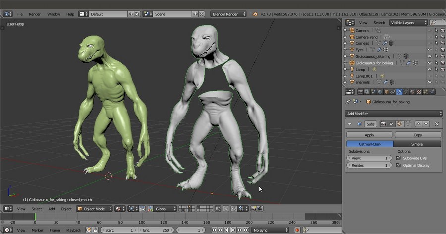
Comparison between the high resolution sculpted mesh and the low resolution object with the baked normal map
As we reopen the mouth by lowering the close_mouth shape key value to 0.000 or also by simply assigning the baked normal map to the Gidiosaurus_lowres object, we see that something is wrong inside the mouth (and, actually, also on the teeth and talons): the normals have been calculated for those parts too, but they show wrong and weird artifacts because there were no counterparts to take the normals from in the sculpted high resolution mesh.
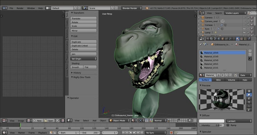
Artifacts of the normal map in some mesh parts
The solution in this case is very simple: we must paint the areas on the baked normal map corresponding to the afflicted parts, such as the teeth, the tongue, and so on, with a flat normal color (R 0.498, G 0.498, B 1.000) to flatten and therefore erase the unwanted details.
We can do this directly in Blender, by selecting the vertices of the areas to be painted on and enabling the mask tool in the 3D viewport toolbar:

Flattening the unwanted artifacts by painting on the normal map
Alternatively, we can do it in an external painting software program such as Gimp; in this case, just delete the vertices of the parts that you don't want to change in the mesh and export the UV layer of all the remaining parts to be used as a guide to paint.
Getting ready
Continue from the previous Gidiosaurus_details_sculpt.blend file:
- Split the 3D viewport into two windows and change the left one into a UV/Image Editor window.
- Go to the 11th scene layer and select the Gidiosaurus_lowres object; press the Tab key to enter Edit Mode and, if necessary, press A to select all the vertices.
- Go to the UV Maps subpanel under the Object Data window, click on the + icon button to add a new UV coordinates layer, rename it as UVMap_norm, and click on the camera icon to make it the active UV layer.
- Put the mouse pointer in the 3D viewport and press U. In the UV Mapping pop-up menu, select the Smart UV Project item; in the pop-up panel, click on the Island Margin value (default = 0.00) and set it to 0.001. Leave the other values as they are and click the big OK button at the bottom of the panel.
The UVMap_norm UV coordinates layer for the low resolution Gidiosaurus mesh
- Deselect all the vertices (the A key again) and zoom to the head; Shift-select the vertices of all the parts that don't actually exist in the high resolution sculpted model such as the inside of the mouth, the mouth inner rims, the tongue, the eyelids, the inside of the nostrils, the teeth, and the talons:
Selecting the low resolution mesh parts that don't have a counterpart in the high resolution sculpted mesh
- Go to the Vertex Groups subpanel under the Object Data window and click on the + icon button to add a new vertex group; rename it as shrinkwrap.
- Press Ctrl + I to invert the selection and then click on the Assign button below the vertex group list window in the Vertex Groups subpanel:
Assigning the inverted selection to the "shrinkwrap" vertex group
- Go out of Edit Mode and press Shift + D to duplicate the Gidiosaurus_lowres object; move the duplicate to the 4th scene layer and in the Outliner window, rename it as Gidiosaurus_for_baking.
- In the Outliner, enable the 3D viewport visibility of the rig; select and move the ctrl_mouth bone upward to close the Gidiosaurus's mouth and then hide the 11th scene layer.
- Reselect the Gidiosaurus_for_baking object and go to the Object Modifiers window; click on the Apply as Shape Key button of the Armature modifier.
- Go to the Shape Keys subpanel under the Object Data window to find a new shape key at the bottom of the list: Armature, with the value of 0.000.
- Rename the new shape key as closed_mouth and set the value to 1.000:
The closed_mouth shape key
- Go to the Object Modifiers window and assign a Shrinkwrap modifier to the Gidiosaurus_for_baking object; as Target, select the Gidiosaurs_detailing object and then click on the Vertex Group slot to select the shrinkwrap vertex group.
In the following screenshot, you can see the effect of the Shrinkwrap modifier on the low resolution mesh with the Subdivision Surface modifier enabled also for the 3D viewport:
The "shrinkwrapped" low resolution Gidiosaurus mesh
After this quite intensive file preparation, let's go with the baking itself:
- Enter Edit Mode and select all the mesh vertices; in the UV/Image Editor window, add a new 3072 x 3072 blank image and rename it as
norm. - Go out of Edit Mode, enable the 14th scene layer, select the Gidiosaurus_detailing object, and then Shift-select the Gidiosaurus_for_baking object.
- Go to the Render window, scroll the panel down and, in the Bake subpanel, check the Selected to Active item. Set Margin to 8 pixels, the Bake Mode to Normals, and the Normal Space to Tangent; click on the Bake button to start the baking:
The baked normals' image map, the two overlapping and selected objects, and the Bake subpanel
- Click on the Image item in the UV/Image Editor window toolbar to save the baked image as
norm.pnginside thetexture_makingfolder.
To close the mouth (to conform it to the sculpted mesh), we moved the control bone in the rig and then applied the Armature modifier as a shape key; be aware that a modifier cannot be applied to a mesh with shape keys (you get a warning message), so we had to use the Apply as Shape Key option or delete all the shape keys with drivers and redo them later. In this case, however, it wouldn't have been necessary to duplicate the Gidiosaurus low resolution mesh, but we did it anyway to keep things simpler and cleaner.
Right before the baking, a Shrinkwrap modifier has been assigned to the lowres Gidiosaurus_for_baking object, to conform its surface to the high resolution sculpted Gidiosaurus_detailing object and avoid any possible intersection between the two meshes (that would give ugly artifacts in the baked image); we used the shrinkwrap vertex group to keep the vertices that don't have a counterpart on the high resolution mesh (teeth, eyelids, inner mouth, and so on) out of the modifier influence.
As you can see in the following OpenGL screenshot, comparing the sculpted and the low res Gidiosaurus meshes, the result of the baked normals on the low resolution object is pretty good and effective:
Comparison between the high resolution sculpted mesh and the low resolution object with the baked normal map
As we reopen the mouth by lowering the close_mouth shape key value to 0.000 or also by simply assigning the baked normal map to the Gidiosaurus_lowres object, we see that something is wrong inside the mouth (and, actually, also on the teeth and talons): the normals have been calculated for those parts too, but they show wrong and weird artifacts because there were no counterparts to take the normals from in the sculpted high resolution mesh.
Artifacts of the normal map in some mesh parts
The solution in this case is very simple: we must paint the areas on the baked normal map corresponding to the afflicted parts, such as the teeth, the tongue, and so on, with a flat normal color (R 0.498, G 0.498, B 1.000) to flatten and therefore erase the unwanted details.
We can do this directly in Blender, by selecting the vertices of the areas to be painted on and enabling the mask tool in the 3D viewport toolbar:
Flattening the unwanted artifacts by painting on the normal map
Alternatively, we can do it in an external painting software program such as Gimp; in this case, just delete the vertices of the parts that you don't want to change in the mesh and export the UV layer of all the remaining parts to be used as a guide to paint.
How to do it…
After this quite intensive file preparation, let's go with the baking itself:
- Enter Edit Mode and select all the mesh vertices; in the UV/Image Editor window, add a new 3072 x 3072 blank image and rename it as
norm. - Go out of Edit Mode, enable the 14th scene layer, select the Gidiosaurus_detailing object, and then Shift-select the Gidiosaurus_for_baking object.
- Go to the Render window, scroll the panel down and, in the Bake subpanel, check the Selected to Active item. Set Margin to 8 pixels, the Bake Mode to Normals, and the Normal Space to Tangent; click on the Bake button to start the baking:
The baked normals' image map, the two overlapping and selected objects, and the Bake subpanel
- Click on the Image item in the UV/Image Editor window toolbar to save the baked image as
norm.pnginside thetexture_makingfolder.
To close the mouth (to conform it to the sculpted mesh), we moved the control bone in the rig and then applied the Armature modifier as a shape key; be aware that a modifier cannot be applied to a mesh with shape keys (you get a warning message), so we had to use the Apply as Shape Key option or delete all the shape keys with drivers and redo them later. In this case, however, it wouldn't have been necessary to duplicate the Gidiosaurus low resolution mesh, but we did it anyway to keep things simpler and cleaner.
Right before the baking, a Shrinkwrap modifier has been assigned to the lowres Gidiosaurus_for_baking object, to conform its surface to the high resolution sculpted Gidiosaurus_detailing object and avoid any possible intersection between the two meshes (that would give ugly artifacts in the baked image); we used the shrinkwrap vertex group to keep the vertices that don't have a counterpart on the high resolution mesh (teeth, eyelids, inner mouth, and so on) out of the modifier influence.
As you can see in the following OpenGL screenshot, comparing the sculpted and the low res Gidiosaurus meshes, the result of the baked normals on the low resolution object is pretty good and effective:
Comparison between the high resolution sculpted mesh and the low resolution object with the baked normal map
As we reopen the mouth by lowering the close_mouth shape key value to 0.000 or also by simply assigning the baked normal map to the Gidiosaurus_lowres object, we see that something is wrong inside the mouth (and, actually, also on the teeth and talons): the normals have been calculated for those parts too, but they show wrong and weird artifacts because there were no counterparts to take the normals from in the sculpted high resolution mesh.
Artifacts of the normal map in some mesh parts
The solution in this case is very simple: we must paint the areas on the baked normal map corresponding to the afflicted parts, such as the teeth, the tongue, and so on, with a flat normal color (R 0.498, G 0.498, B 1.000) to flatten and therefore erase the unwanted details.
We can do this directly in Blender, by selecting the vertices of the areas to be painted on and enabling the mask tool in the 3D viewport toolbar:
Flattening the unwanted artifacts by painting on the normal map
Alternatively, we can do it in an external painting software program such as Gimp; in this case, just delete the vertices of the parts that you don't want to change in the mesh and export the UV layer of all the remaining parts to be used as a guide to paint.
How it works…
To close the mouth (to conform it to the sculpted mesh), we moved the control bone in the rig and then applied the Armature modifier as a shape key; be aware that a modifier cannot be applied to a mesh with shape keys (you get a warning message), so we had to use the Apply as Shape Key option or delete all the shape keys with drivers and redo them later. In this case, however, it wouldn't have been necessary to duplicate the Gidiosaurus low resolution mesh, but we did it anyway to keep things simpler and cleaner.
Right before the baking, a Shrinkwrap modifier has been assigned to the lowres Gidiosaurus_for_baking object, to conform its surface to the high resolution sculpted Gidiosaurus_detailing object and avoid any possible intersection between the two meshes (that would give ugly artifacts in the baked image); we used the shrinkwrap vertex group to keep the vertices that don't have a counterpart on the high resolution mesh (teeth, eyelids, inner mouth, and so on) out of the modifier influence.
As you can see in the following OpenGL screenshot, comparing the sculpted and the low res Gidiosaurus meshes, the result of the baked normals on the low resolution object is pretty good and effective:
Comparison between the high resolution sculpted mesh and the low resolution object with the baked normal map
As we reopen the mouth by lowering the close_mouth shape key value to 0.000 or also by simply assigning the baked normal map to the Gidiosaurus_lowres object, we see that something is wrong inside the mouth (and, actually, also on the teeth and talons): the normals have been calculated for those parts too, but they show wrong and weird artifacts because there were no counterparts to take the normals from in the sculpted high resolution mesh.
Artifacts of the normal map in some mesh parts
The solution in this case is very simple: we must paint the areas on the baked normal map corresponding to the afflicted parts, such as the teeth, the tongue, and so on, with a flat normal color (R 0.498, G 0.498, B 1.000) to flatten and therefore erase the unwanted details.
We can do this directly in Blender, by selecting the vertices of the areas to be painted on and enabling the mask tool in the 3D viewport toolbar:
Flattening the unwanted artifacts by painting on the normal map
Alternatively, we can do it in an external painting software program such as Gimp; in this case, just delete the vertices of the parts that you don't want to change in the mesh and export the UV layer of all the remaining parts to be used as a guide to paint.
There's more…
As we reopen the mouth by lowering the close_mouth shape key value to 0.000 or also by simply assigning the baked normal map to the Gidiosaurus_lowres object, we see that something is wrong inside the mouth (and, actually, also on the teeth and talons): the normals have been calculated for those parts too, but they show wrong and weird artifacts because there were no counterparts to take the normals from in the sculpted high resolution mesh.
Artifacts of the normal map in some mesh parts
The solution in this case is very simple: we must paint the areas on the baked normal map corresponding to the afflicted parts, such as the teeth, the tongue, and so on, with a flat normal color (R 0.498, G 0.498, B 1.000) to flatten and therefore erase the unwanted details.
We can do this directly in Blender, by selecting the vertices of the areas to be painted on and enabling the mask tool in the 3D viewport toolbar:
Flattening the unwanted artifacts by painting on the normal map
Alternatively, we can do it in an external painting software program such as Gimp; in this case, just delete the vertices of the parts that you don't want to change in the mesh and export the UV layer of all the remaining parts to be used as a guide to paint.
The same procedure used in the previous recipe must be used for the Armor object, to bake the normals of the sculpted high resolution version on the low poly one.
So, in short, we will do the following:
- Enable the 13th scene layer; select the Armor object and go to the Object Modifiers window.
- Temporarily, disable the Armature modifier both for rendering, and the viewport, and be sure that the Subdivision Surface modifier levels are both set to 2.
- Assign a Shrinkwrap modifier with a target to the Armor_detailing object; in the Vertex Group slot, select the shrinkwrap vertex group and, just to be sure, also check the Keep Above Surface item.
Also, in this case, thanks to the shrinkwrap vertex group, only the outside of the armor mesh is conformed to the sculpted mesh; the insides are not important and can even be deleted (only for the baking and, of course, on a duplicated armor object, as we did with the Gidiosaurus_for_baking object). In any case, they will be barely visible.

The Armor object prepared for the baking
Let's now bake the sculpted geometry in a few steps:
- Enter Edit Mode and select all the mesh vertices; in the UV/Image Editor window, add a new 3072 x 3072 blank image and rename it as
norm2. - Go out of Edit Mode, enable the 3rd scene layer and select the Armor_detailing object, and then Shift-select the Armor object.
- Go to the Render window, scroll the panel down; in the Bake subpanel, check the Selected to Active item, and set the Margin to 8 pixels, the Bake Mode to Normals, and the Normal Space to Tangent. Then, click on the Bake button.
- Click on the Image item on the UV/Image Editor window toolbar to save the baked image as
norm2.png, inside thetexture_makingfolder. - Save the file as
Gidiosaurus_baking_normals.blend.
In the following OpenGL screenshot, you can see the comparison between the sculpted and the low resolution Armor objects with the assigned normal map:

A comparison between the sculpted and the normal map versions of the Armor
Inside the texture_making folder provided with this cookbook, there is also an already seamless iron_tiles.png image to be used for the Armor; it has been made seamless in Gimp, but after the mapping on the model, we'll need to fix some visible seams again by using the Clone brush of the Blender Paint Tool.
I won't go through all the required steps here, because this would be a repetition of recipes already explained in Chapter 10, Creating the Textures.
So, we have to add two materials to the Armor object; each one with its own image texture and assigned to the vertices corresponding to each tile, and then also add the iron_tiles.png image to each affected material.
In short, we have to replicate the steps of the Preparing the model to use the UDIM UV tiles, Baking the tileable scales texture into the UV tiles, and Painting to fix the seams and to modify the baked scales image maps recipes from Chapter 10, Creating the Textures.
To use the Clone brush (press the 1 key to call it after entering Texture Paint mode), press Ctrl + left-click on the area of the mesh you want to clone from; this will place the 3D Cursor in that location. Then, left-click on the seams to clone the texture from the area under the 3D Cursor:
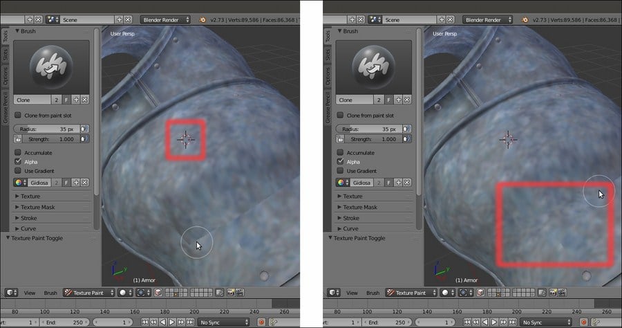
The Clone brush is cloning the texture area at the 3D Cursor location
Besides the Clone brush, in this case, it is also possible to fix the seams with the Smear brush (4 key).
When you are done, save the two iron images as iron_U0V0.png and iron_U1V0.png inside the texture folder.
Getting ready
So, in short, we will do the following:
- Enable the 13th scene layer; select the Armor object and go to the Object Modifiers window.
- Temporarily, disable the Armature modifier both for rendering, and the viewport, and be sure that the Subdivision Surface modifier levels are both set to 2.
- Assign a Shrinkwrap modifier with a target to the Armor_detailing object; in the Vertex Group slot, select the shrinkwrap vertex group and, just to be sure, also check the Keep Above Surface item.
Also, in this case, thanks to the shrinkwrap vertex group, only the outside of the armor mesh is conformed to the sculpted mesh; the insides are not important and can even be deleted (only for the baking and, of course, on a duplicated armor object, as we did with the Gidiosaurus_for_baking object). In any case, they will be barely visible.
The Armor object prepared for the baking
Let's now bake the sculpted geometry in a few steps:
- Enter Edit Mode and select all the mesh vertices; in the UV/Image Editor window, add a new 3072 x 3072 blank image and rename it as
norm2. - Go out of Edit Mode, enable the 3rd scene layer and select the Armor_detailing object, and then Shift-select the Armor object.
- Go to the Render window, scroll the panel down; in the Bake subpanel, check the Selected to Active item, and set the Margin to 8 pixels, the Bake Mode to Normals, and the Normal Space to Tangent. Then, click on the Bake button.
- Click on the Image item on the UV/Image Editor window toolbar to save the baked image as
norm2.png, inside thetexture_makingfolder. - Save the file as
Gidiosaurus_baking_normals.blend.
In the following OpenGL screenshot, you can see the comparison between the sculpted and the low resolution Armor objects with the assigned normal map:
A comparison between the sculpted and the normal map versions of the Armor
Inside the texture_making folder provided with this cookbook, there is also an already seamless iron_tiles.png image to be used for the Armor; it has been made seamless in Gimp, but after the mapping on the model, we'll need to fix some visible seams again by using the Clone brush of the Blender Paint Tool.
I won't go through all the required steps here, because this would be a repetition of recipes already explained in Chapter 10, Creating the Textures.
So, we have to add two materials to the Armor object; each one with its own image texture and assigned to the vertices corresponding to each tile, and then also add the iron_tiles.png image to each affected material.
In short, we have to replicate the steps of the Preparing the model to use the UDIM UV tiles, Baking the tileable scales texture into the UV tiles, and Painting to fix the seams and to modify the baked scales image maps recipes from Chapter 10, Creating the Textures.
To use the Clone brush (press the 1 key to call it after entering Texture Paint mode), press Ctrl + left-click on the area of the mesh you want to clone from; this will place the 3D Cursor in that location. Then, left-click on the seams to clone the texture from the area under the 3D Cursor:
The Clone brush is cloning the texture area at the 3D Cursor location
Besides the Clone brush, in this case, it is also possible to fix the seams with the Smear brush (4 key).
When you are done, save the two iron images as iron_U0V0.png and iron_U1V0.png inside the texture folder.
How to do it…
Let's now bake the sculpted geometry in a few steps:
- Enter Edit Mode and select all the mesh vertices; in the UV/Image Editor window, add a new 3072 x 3072 blank image and rename it as
norm2. - Go out of Edit Mode, enable the 3rd scene layer and select the Armor_detailing object, and then Shift-select the Armor object.
- Go to the Render window, scroll the panel down; in the Bake subpanel, check the Selected to Active item, and set the Margin to 8 pixels, the Bake Mode to Normals, and the Normal Space to Tangent. Then, click on the Bake button.
- Click on the Image item on the UV/Image Editor window toolbar to save the baked image as
norm2.png, inside thetexture_makingfolder. - Save the file as
Gidiosaurus_baking_normals.blend.
In the following OpenGL screenshot, you can see the comparison between the sculpted and the low resolution Armor objects with the assigned normal map:
A comparison between the sculpted and the normal map versions of the Armor
Inside the texture_making folder provided with this cookbook, there is also an already seamless iron_tiles.png image to be used for the Armor; it has been made seamless in Gimp, but after the mapping on the model, we'll need to fix some visible seams again by using the Clone brush of the Blender Paint Tool.
I won't go through all the required steps here, because this would be a repetition of recipes already explained in Chapter 10, Creating the Textures.
So, we have to add two materials to the Armor object; each one with its own image texture and assigned to the vertices corresponding to each tile, and then also add the iron_tiles.png image to each affected material.
In short, we have to replicate the steps of the Preparing the model to use the UDIM UV tiles, Baking the tileable scales texture into the UV tiles, and Painting to fix the seams and to modify the baked scales image maps recipes from Chapter 10, Creating the Textures.
To use the Clone brush (press the 1 key to call it after entering Texture Paint mode), press Ctrl + left-click on the area of the mesh you want to clone from; this will place the 3D Cursor in that location. Then, left-click on the seams to clone the texture from the area under the 3D Cursor:
The Clone brush is cloning the texture area at the 3D Cursor location
Besides the Clone brush, in this case, it is also possible to fix the seams with the Smear brush (4 key).
When you are done, save the two iron images as iron_U0V0.png and iron_U1V0.png inside the texture folder.
There's more…
Inside the texture_making folder provided with this cookbook, there is also an already seamless iron_tiles.png image to be used for the Armor; it has been made seamless in Gimp, but after the mapping on the model, we'll need to fix some visible seams again by using the Clone brush of the Blender Paint Tool.
I won't go through all the required steps here, because this would be a repetition of recipes already explained in Chapter 10, Creating the Textures.
So, we have to add two materials to the Armor object; each one with its own image texture and assigned to the vertices corresponding to each tile, and then also add the iron_tiles.png image to each affected material.
In short, we have to replicate the steps of the Preparing the model to use the UDIM UV tiles, Baking the tileable scales texture into the UV tiles, and Painting to fix the seams and to modify the baked scales image maps recipes from Chapter 10, Creating the Textures.
To use the Clone brush (press the 1 key to call it after entering Texture Paint mode), press Ctrl + left-click on the area of the mesh you want to clone from; this will place the 3D Cursor in that location. Then, left-click on the seams to clone the texture from the area under the 3D Cursor:
The Clone brush is cloning the texture area at the 3D Cursor location
Besides the Clone brush, in this case, it is also possible to fix the seams with the Smear brush (4 key).
When you are done, save the two iron images as iron_U0V0.png and iron_U1V0.png inside the texture folder.
Let's see now how to add a dirty map through the Vertex Colors tool and how to bake it to an image texture; such a texture map can be useful for the creation of the shaders (which we'll see in the next chapter).
To do this, we are going to use an already set .blend file:
- Start Blender and open the
Gidiosaurus_baking_normals.blendfile; save it asGidiosaurus_baking_dirty.blend. - Put the mouse pointer in the 3D view and press the Z key twice to switch into Solid viewport shading mode; click on the 14th scene layer to enable the visibility of the Gidiosaurus_detailing object.
Let's first go with the creation of the Vertex Colors layer:
- In the Outliner, select the Gidiosaurus_detailing object and then click on the mode button in the 3D viewport toolbar to select the Vertex Paint mode:

Selecting the Vertex Paint mode item
- Now, click on the Paint item in the 3D viewport toolbar and from the menu, select the Dirty Vertex Colors item; the Gidiosaurus mesh, first filled with a plain white color, gets shaded in grayscale tones:

Using the Dirty Vertex Colors tool
- Expand the last operation panel at the bottom of the Tool Shelf and press Ctrl+click on the Dirt Angle slot to enter the value 90°; the grayscale shading on the mesh gets a lot more darker and contrasted:

Tweaking the settings for the Dirty Vertex Colors tool
- Go back in Object Mode and then move to the Material window, where the Body material is already assigned to the high resolution mesh. Scroll down the panel to reach the Shading subpanel and enable the Shadeless item; then, reach down the Options subpanel and enable the Vertex Color Paint item:

The Shadeless and the Vertex Color Paint items
To understand the effect of the items we enabled in the Material window, just switch to the Rendered viewport shading mode; the mesh surface is self-illuminating and showing the dirty Vertex Colors layer:

The Dirty Vertex Colors layer visualized in the Rendered preview
Note that the Shadeless item is not actually mandatory for the baking, but is only required to see the object in the Rendered viewport shading mode as in the previous screenshot.
- Also, enable the 4th scene layer (Shift+left-click) and in the Outliner window, select the Gidiosaurus_for_baking object. Go to the Object Data window to be sure that the UVMap_norm layer is the active one and then go to the Render window and scroll down to the bottom, to the Bake subpanel; click on the Bake Mode slot to select the Textures item from the pop-up menu:

Baking the Dirty Vertex Colors layer to Textures
- With the Gidiosaurus_for_baking object still selected, enter Edit Mode and select all the vertices; in the UV/Image Editor window, add a new 3072 x 3072 blank image renamed as
vcol. - Go out of Edit Mode and in the Outliner, select the Gidiosaurus_detailing object; then, Shift-select the Gidiosaurus_for_baking object and go to the Bake subpanel under the Render window to click on the Bake button:

The final baked "vcol.png" image map
- Save the baked image as
vcol.pnginto thetexture_makingfolder. - Enable the 3rd scene layer, select the Armor_detailing object, and repeat the procedure; save the baked image as
vcol2.pngin thetexture_makingfolder and also save the file:
The baked vertex color layer for the Armor
The Vertex Colors tool can add a color to each vertex of the mesh, so it's actually possible to paint an object without the need for an image texture; the denser the mesh, the better this works.
The Dirty Vertex Colors tool uses the proximity and the depth of folds and creases on the mesh surface to calculate grayscale values to be assigned to the vertices; thanks to the Vertex Color Paint item, enabled in the Material window, this grayscale shows up in the rendering and so it's also possible to bake it into an image.
Getting ready
To do this, we are going to use an already set .blend file:
- Start Blender and open the
Gidiosaurus_baking_normals.blendfile; save it asGidiosaurus_baking_dirty.blend. - Put the mouse pointer in the 3D view and press the Z key twice to switch into Solid viewport shading mode; click on the 14th scene layer to enable the visibility of the Gidiosaurus_detailing object.
Let's first go with the creation of the Vertex Colors layer:
- In the Outliner, select the Gidiosaurus_detailing object and then click on the mode button in the 3D viewport toolbar to select the Vertex Paint mode:
Selecting the Vertex Paint mode item
- Now, click on the Paint item in the 3D viewport toolbar and from the menu, select the Dirty Vertex Colors item; the Gidiosaurus mesh, first filled with a plain white color, gets shaded in grayscale tones:
Using the Dirty Vertex Colors tool
- Expand the last operation panel at the bottom of the Tool Shelf and press Ctrl+click on the Dirt Angle slot to enter the value 90°; the grayscale shading on the mesh gets a lot more darker and contrasted:
Tweaking the settings for the Dirty Vertex Colors tool
- Go back in Object Mode and then move to the Material window, where the Body material is already assigned to the high resolution mesh. Scroll down the panel to reach the Shading subpanel and enable the Shadeless item; then, reach down the Options subpanel and enable the Vertex Color Paint item:
The Shadeless and the Vertex Color Paint items
To understand the effect of the items we enabled in the Material window, just switch to the Rendered viewport shading mode; the mesh surface is self-illuminating and showing the dirty Vertex Colors layer:
The Dirty Vertex Colors layer visualized in the Rendered preview
Note that the Shadeless item is not actually mandatory for the baking, but is only required to see the object in the Rendered viewport shading mode as in the previous screenshot.
- Also, enable the 4th scene layer (Shift+left-click) and in the Outliner window, select the Gidiosaurus_for_baking object. Go to the Object Data window to be sure that the UVMap_norm layer is the active one and then go to the Render window and scroll down to the bottom, to the Bake subpanel; click on the Bake Mode slot to select the Textures item from the pop-up menu:
Baking the Dirty Vertex Colors layer to Textures
- With the Gidiosaurus_for_baking object still selected, enter Edit Mode and select all the vertices; in the UV/Image Editor window, add a new 3072 x 3072 blank image renamed as
vcol. - Go out of Edit Mode and in the Outliner, select the Gidiosaurus_detailing object; then, Shift-select the Gidiosaurus_for_baking object and go to the Bake subpanel under the Render window to click on the Bake button:
The final baked "vcol.png" image map
- Save the baked image as
vcol.pnginto thetexture_makingfolder. - Enable the 3rd scene layer, select the Armor_detailing object, and repeat the procedure; save the baked image as
vcol2.pngin thetexture_makingfolder and also save the file:The baked vertex color layer for the Armor
The Vertex Colors tool can add a color to each vertex of the mesh, so it's actually possible to paint an object without the need for an image texture; the denser the mesh, the better this works.
The Dirty Vertex Colors tool uses the proximity and the depth of folds and creases on the mesh surface to calculate grayscale values to be assigned to the vertices; thanks to the Vertex Color Paint item, enabled in the Material window, this grayscale shows up in the rendering and so it's also possible to bake it into an image.
How to do it…
Let's first go with the creation of the Vertex Colors layer:
- In the Outliner, select the Gidiosaurus_detailing object and then click on the mode button in the 3D viewport toolbar to select the Vertex Paint mode:
Selecting the Vertex Paint mode item
- Now, click on the Paint item in the 3D viewport toolbar and from the menu, select the Dirty Vertex Colors item; the Gidiosaurus mesh, first filled with a plain white color, gets shaded in grayscale tones:
Using the Dirty Vertex Colors tool
- Expand the last operation panel at the bottom of the Tool Shelf and press Ctrl+click on the Dirt Angle slot to enter the value 90°; the grayscale shading on the mesh gets a lot more darker and contrasted:
Tweaking the settings for the Dirty Vertex Colors tool
- Go back in Object Mode and then move to the Material window, where the Body material is already assigned to the high resolution mesh. Scroll down the panel to reach the Shading subpanel and enable the Shadeless item; then, reach down the Options subpanel and enable the Vertex Color Paint item:
The Shadeless and the Vertex Color Paint items
To understand the effect of the items we enabled in the Material window, just switch to the Rendered viewport shading mode; the mesh surface is self-illuminating and showing the dirty Vertex Colors layer:
The Dirty Vertex Colors layer visualized in the Rendered preview
Note that the Shadeless item is not actually mandatory for the baking, but is only required to see the object in the Rendered viewport shading mode as in the previous screenshot.
- Also, enable the 4th scene layer (Shift+left-click) and in the Outliner window, select the Gidiosaurus_for_baking object. Go to the Object Data window to be sure that the UVMap_norm layer is the active one and then go to the Render window and scroll down to the bottom, to the Bake subpanel; click on the Bake Mode slot to select the Textures item from the pop-up menu:
Baking the Dirty Vertex Colors layer to Textures
- With the Gidiosaurus_for_baking object still selected, enter Edit Mode and select all the vertices; in the UV/Image Editor window, add a new 3072 x 3072 blank image renamed as
vcol. - Go out of Edit Mode and in the Outliner, select the Gidiosaurus_detailing object; then, Shift-select the Gidiosaurus_for_baking object and go to the Bake subpanel under the Render window to click on the Bake button:
The final baked "vcol.png" image map
- Save the baked image as
vcol.pnginto thetexture_makingfolder. - Enable the 3rd scene layer, select the Armor_detailing object, and repeat the procedure; save the baked image as
vcol2.pngin thetexture_makingfolder and also save the file:The baked vertex color layer for the Armor
The Vertex Colors tool can add a color to each vertex of the mesh, so it's actually possible to paint an object without the need for an image texture; the denser the mesh, the better this works.
The Dirty Vertex Colors tool uses the proximity and the depth of folds and creases on the mesh surface to calculate grayscale values to be assigned to the vertices; thanks to the Vertex Color Paint item, enabled in the Material window, this grayscale shows up in the rendering and so it's also possible to bake it into an image.
How it works…
The Vertex Colors tool can add a color to each vertex of the mesh, so it's actually possible to paint an object without the need for an image texture; the denser the mesh, the better this works.
The Dirty Vertex Colors tool uses the proximity and the depth of folds and creases on the mesh surface to calculate grayscale values to be assigned to the vertices; thanks to the Vertex Color Paint item, enabled in the Material window, this grayscale shows up in the rendering and so it's also possible to bake it into an image.
It's time to talk a bit about a very useful Blender tool: the Quick Edit tool.
Through this tool, it's possible to export a screenshot of the model in our favorite 2D painting software (Gimp or Photoshop, or whatever), paint on it using a new alpha background layer, and reassign the painted layer to the model in Blender, which is UV-mapped on the selected UV coordinates layer. All this, in just a few clicks.
In our case, we don't actually need to use this tool to refine the textures for the Gidiosaurus, so this recipe is going to be just an example. By the way, to fully understand how to use the tool, I suggest you to follow all the steps; just don't save the file at the end (or save it with a different name in a different directory if you want to keep it). So, carry on with the following:
- Start Blender and call the User Preferences panel (Ctrl + Alt + U); go to the File tab and, in the Image Editor slot (Path to an image editor), write the path to your 2D image painting software installation (this is also done by clicking on the open/browse button at the right end of the slot). The path, of course, changes based on your OS; in my case, in Linux Ubuntu, it's enough to write
gimp:
The Image Editor path in the File tab of the User Preferences panel under Linux Ubuntu
- Click on the Save User Settings button at the bottom-left of the panel and close it.
Once you've set the path to the image editor, let's load our Gidiosaurus file:
- Load the
Gidiosaurus_painting_BI.blendfile and maximize it as much as possible in the 3D viewport.You can use both the User or the Camera view; it doesn't make any difference for the tool to work. By the way, it would be a good idea to use the Camera view so as to have a fixed point of view for any other case.
- If necessary, press the T key to call the Tool Shelf panel; select the Gidiosaurus object and then go in Texture Paint mode.
- Go to the External subpanel under the Tools tab; set a size for the screenshot to be exported (by default, it's 512 x 512 pixels; I set it to 3072 x 3072 pixels) and then click on the Quick Edit button:

The External Image Editor subpanel
After a while, the image editor automatically starts (in my case, it's Gimp 2.8) and opens the screenshot of the model:

The screenshot previously visible in the Blender Camera view opened in Gimp
- Add a new transparent layer and start to paint on it, adding some kind of tribal make-up decoration to the Gidiosaurus:

Tribal painting on the Gidiosaurus warrior
- When you are done, deselect the visibility for the export layer and export the transparent painted one by saving it with the same name as the exported one. That is, the Quick Edit tool exported the screenshot by saving a
.pngimage inside the blend file directory with the nameGidiosaurus_painting_BI_02_Gidiosaurus_lowres.png; export the painted layer by saving it asGidiosaurus_painting_BI_02_Gidiosaurus_lowres.pngas well:
The Gimp layer with the tribal painting "a solo"
This is necessary for Blender to find it in the next step.
- Back in Blender, click on the Apply button under the External subpanel and watch the new layer added to the model in the 3D viewport:

- To make the textures editing permanent, click on the Save All Images button, both under the Slots tab and the Image item on the UV/Image Editor window toolbar:

The tribal painting transferred on the 3D model
The editing we did in Gimp is now correctly transferred on the image textures:

The tribal painting transferred on the image map
Getting ready
In our case, we don't actually need to use this tool to refine the textures for the Gidiosaurus, so this recipe is going to be just an example. By the way, to fully understand how to use the tool, I suggest you to follow all the steps; just don't save the file at the end (or save it with a different name in a different directory if you want to keep it). So, carry on with the following:
- Start Blender and call the User Preferences panel (Ctrl + Alt + U); go to the File tab and, in the Image Editor slot (Path to an image editor), write the path to your 2D image painting software installation (this is also done by clicking on the open/browse button at the right end of the slot). The path, of course, changes based on your OS; in my case, in Linux Ubuntu, it's enough to write
gimp:The Image Editor path in the File tab of the User Preferences panel under Linux Ubuntu
- Click on the Save User Settings button at the bottom-left of the panel and close it.
Once you've set the path to the image editor, let's load our Gidiosaurus file:
- Load the
Gidiosaurus_painting_BI.blendfile and maximize it as much as possible in the 3D viewport.You can use both the User or the Camera view; it doesn't make any difference for the tool to work. By the way, it would be a good idea to use the Camera view so as to have a fixed point of view for any other case.
- If necessary, press the T key to call the Tool Shelf panel; select the Gidiosaurus object and then go in Texture Paint mode.
- Go to the External subpanel under the Tools tab; set a size for the screenshot to be exported (by default, it's 512 x 512 pixels; I set it to 3072 x 3072 pixels) and then click on the Quick Edit button:
The External Image Editor subpanel
After a while, the image editor automatically starts (in my case, it's Gimp 2.8) and opens the screenshot of the model:
The screenshot previously visible in the Blender Camera view opened in Gimp
- Add a new transparent layer and start to paint on it, adding some kind of tribal make-up decoration to the Gidiosaurus:
Tribal painting on the Gidiosaurus warrior
- When you are done, deselect the visibility for the export layer and export the transparent painted one by saving it with the same name as the exported one. That is, the Quick Edit tool exported the screenshot by saving a
.pngimage inside the blend file directory with the nameGidiosaurus_painting_BI_02_Gidiosaurus_lowres.png; export the painted layer by saving it asGidiosaurus_painting_BI_02_Gidiosaurus_lowres.pngas well:The Gimp layer with the tribal painting "a solo"
This is necessary for Blender to find it in the next step.
- Back in Blender, click on the Apply button under the External subpanel and watch the new layer added to the model in the 3D viewport:
- To make the textures editing permanent, click on the Save All Images button, both under the Slots tab and the Image item on the UV/Image Editor window toolbar:
The tribal painting transferred on the 3D model
The editing we did in Gimp is now correctly transferred on the image textures:
The tribal painting transferred on the image map
How to do it…
Once you've set the path to the image editor, let's load our Gidiosaurus file:
- Load the
Gidiosaurus_painting_BI.blendfile and maximize it as much as possible in the 3D viewport.You can use both the User or the Camera view; it doesn't make any difference for the tool to work. By the way, it would be a good idea to use the Camera view so as to have a fixed point of view for any other case.
- If necessary, press the T key to call the Tool Shelf panel; select the Gidiosaurus object and then go in Texture Paint mode.
- Go to the External subpanel under the Tools tab; set a size for the screenshot to be exported (by default, it's 512 x 512 pixels; I set it to 3072 x 3072 pixels) and then click on the Quick Edit button:
The External Image Editor subpanel
After a while, the image editor automatically starts (in my case, it's Gimp 2.8) and opens the screenshot of the model:
The screenshot previously visible in the Blender Camera view opened in Gimp
- Add a new transparent layer and start to paint on it, adding some kind of tribal make-up decoration to the Gidiosaurus:
Tribal painting on the Gidiosaurus warrior
- When you are done, deselect the visibility for the export layer and export the transparent painted one by saving it with the same name as the exported one. That is, the Quick Edit tool exported the screenshot by saving a
.pngimage inside the blend file directory with the nameGidiosaurus_painting_BI_02_Gidiosaurus_lowres.png; export the painted layer by saving it asGidiosaurus_painting_BI_02_Gidiosaurus_lowres.pngas well:The Gimp layer with the tribal painting "a solo"
This is necessary for Blender to find it in the next step.
- Back in Blender, click on the Apply button under the External subpanel and watch the new layer added to the model in the 3D viewport:
- To make the textures editing permanent, click on the Save All Images button, both under the Slots tab and the Image item on the UV/Image Editor window toolbar:
The tribal painting transferred on the 3D model
The editing we did in Gimp is now correctly transferred on the image textures:
The tribal painting transferred on the image map
In this chapter, we will cover the following recipes:
- Building the reptile skin shaders in Cycles
- Making a node group of the skin shader to reuse it
- Building the eyes' shaders in Cycles
- Building the armor shaders in Cycles
In Chapter 10, Creating the Textures, and in Chapter 11, Refining the Textures, we have prepared all the necessary texture images for the Gidiosaurus skin and for the iron Armor (the creation process for some textures, specifically the two textures for the character's eyes, hasn't been described, but basically it's a process similar to what we have already seen).
In this chapter, we'll see how to use these textures and how to set up the materials for the Gidiosaurus and the Armor in the Cycles Render engine.
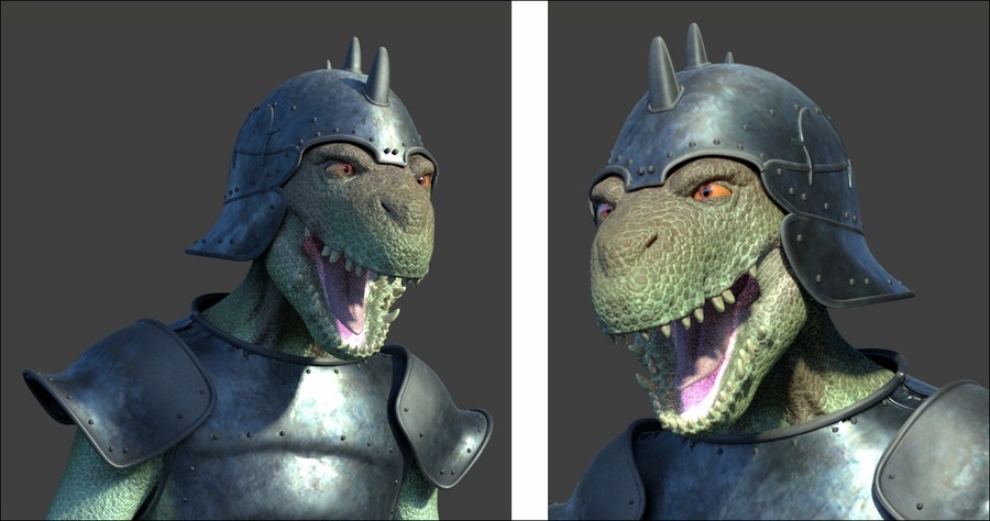
A rendered example of the Cycles' shader final result
So, let's start with the Gidiosaurus skin.
But first, as usual, we must prepare the file:
- As the very first step, go to the
texture_makingfolder and move the texturesvcol.png,vcol2.png,norm.png, andnorm2.pngto thetexturesfolder. - Then start Blender and open the
Gidiosaurus_baking_normals.blendfile we saved in Chapter 11, Refining the Textures. - Switch the left UV/Image Editor window with a Node Editor window and press the N key to get rid of the Properties sidebar. Put the mouse pointer in the 3D viewport to the right and press the T key to get rid of the Tool Shelf panel, then press the Z key twice to go in Solid viewport shading mode.
- Enable the 3rd scene layer, select and delete the Armor_detailing object (press the X key, then left-click to confirm).
- Enable the 4th scene layer and select and delete the Gidiosaurus_for_baking object as well. Enable the 14th scene layer, and also select and delete the Gidiosaurus_detailing and the enamels objects.
- Enable the 11th scene layer and right-click on the Gidiosaurus_lowres object to select it.
- It's not mandatory but, in case it is not already disabled, it is best to go to the Object Modifiers window and disable the Armature modifier visibility in the viewport by clicking on the eye icon button.
- Go to the UV Maps subpanel under the Object Data window and select the UVMap coordinates layer (the first one); press Tab to enter Edit Mode, then click on the + icon button to the right side of the UV Maps subpanel to add a new coordinates layer; rename it UVMap2.
- Go to the left window and change it into a UV/Image Editor; one by one, select the UV islands of the talons (at the moment these are placed inside the other UDIM tile spaces), and move them to the default U0V0 tile, to overlap the location of the teeth islands. The reason for this will be clear later, when we will reuse the same color map both for the teeth and for all the talons.
- If necessary, remember to disable the Keep UV and edit mode mesh selection in sync button on the UV/Image Editor toolbar:

Moving the talon islands to overlap the teeth islands inside the default U0V0 tile space
- Go out of Edit Mode and switch the UV/Image Editor window back to a Node Editor window.
- Click on the Engine to use for rendering slot on the main top header to switch to the Cycles Render engine.
- Also, enable the 6th scene layer to show the Lamps. Go to the Outliner, unhide and delete the Lamp.001 object and select the Lamp object; in the Object Data window, change the type to Spot and then click on the Use Nodes button. Set the Strength to 10.000 and the Color to R 1.000, G 1.000, B 0.650, then set the Size to 0.500 and enable the Multiple Importance item (the Multiple Importance Sampling helps in reducing noise for big lamps and sharp glossy reflections, at the cost of the samples rendering a bit slower).
- Put the mouse pointer in the 3D viewport and press N to call the Properties sidepanel; in the top Transform subpanel, type: Location X = 6.059204, Y = -9.912249 and Z = 7.546275, and Rotation X = 55.788944°, Y = 0° and Z = 30.561825°.
- Go to the Render window and, under the Sampling subpanel, set the Samples to 400 for Render and 300 for Preview.
- Go down to the Light Paths subpanel and disable the Reflective Caustics item, then set Filter Glossy to 1.000.
- Re-select the Gidiosaurus_lowres object and go to the Material window:

The 5 materials under the Cycles render engine
As you can see in the previous screenshot, the Gidiosaurus_lowres object has already assigned the 5 materials corresponding to the 5 UDIM tile spaces (see Chapter 5, Unwrapping the Low Resolution Mesh, and Chapter 10, Creating the Textures).
The materials have been created under Blender Internal so, switching to Cycles, they show but aren't initialized as node materials yet; besides this, just before starting the creation of the first Cycles material, we must add two more materials.
- Click the + icon button twice (Add a new material slot) to the right side of the Material window to add two new material slots.
- Select the penultimate slot and click on the New button; rename the new material as
Material_enamels. Select the last slot, click on the New button and rename it asMaterial_wet_U0V0. - Press Tab to enter Edit Mode and select all the vertices of the teeth and the talons; assign them to the
Material_enamelsslot. - Zoom on the Gidiosaurus head; select the vertices of the inner nostrils, of the inner edges of the eyelids and of the tongue, as shown in the following screenshot, and assign them to the
Material_wet_U0V0slot:
Selecting the vertices of the "wet" areas of the character's head to assign them to the "Material_wet_U0V0" slot
- Save the file as
Gidiosaurus_shaders_start.blendfile.
We know that the skin of our character is shared in 5 different materials; we are going to focus on the head (Material_U0V0), as the more representative one.
Once we are happy with the result, we will also copy (with all the due differences) the material to the other body parts.
Therefore, the steps are as follows:
- In the materials list inside the Material window, select the
Material_U0V0(the first top one) and press Ctrl + left-click on it to rename it asMaterial_skin_U0V0; then, move down and click on the Use Nodes button inside the Surface subpanel.Immediately, a Diffuse BSDF shader node (already connected to a Material Output node) appears inside the Node Editor window to the left of the screen and listed in the Surface slot inside the Surface subpanel to the right:

The Diffuse BSDF shader node connected to the Material Output node
- In the Surface subpanel, under the Material window, click on the Surface slot that now shows the Diffuse BSDF shader: in the pop-up menu that appears, select a Mix Shader node:

Switching the Diffuse BSDF shader node with a Mix Shader node through the Material window drop-down list
The Surface slot now shows the Mix Shader node item, and right below there are two new Shader slots that at the moment show the None item; in fact, looking at the nodes inside the Node Editor window, we see that the Diffuse BSDF shader node has been replaced by a Mix Shader node, and that the two (green) Shader input sockets are still empty:

The Mix Shader node with its two shader input sockets in the UV/Image Editor window and in the Material window
- Click on the first Shader slot under the Surface subpanel to select, again from the pop-up menu, a Diffuse BSDF shader node; click on the second Shader slot and select a Mix Shader node; both the two new nodes are added and connected to the proper input socket, as we can see in the Node Editor window:

Two new nodes connected to the two shader input sockets of the Mix Shader node
At this point, to avoid confusion, it's already better to start to label the various nodes with meaningful names.
- Put the mouse pointer inside the Node Editor window and press the N key to call the Properties sidepanel.
- Select the last Mix Shader node we added to the material and then go to click on the Label slot inside the top Name subpanel of the side Properties panel: type Mix Shader1:

Labeling the nodes
- Select the other Mix Shader node (the old one) and repeat the procedure by labeling it as Mix Shader2:

Labeling the nodes again
- Put the mouse pointer on the 3D viewport and press the 0 key on the numpad to enter the Camera view.
- Press Shift + B and by left-clicking draw a box around the head of the Gidiosaurus character to crop the area that can be rendered.
- Zoom to the red square by scrolling the mouse wheel and then press Shift + Z to switch the Viewport Shading mode to Rendered:

Cropping the renderable area and zooming to it
- Put the mouse pointer inside the Node Editor window and press Shift + A. In the pop-up panel that appears, navigate to Shader and then click on the Glossy BSDF item to add the node; as it appears, move the mouse to place it to the left side of the Mix Shader1 node.
- Label it as Glossy BSDF1, connect its output to the first top Shader input socket of the Mix Shader1 node, and set Distribution to Beckmann:

Adding a Glossy BSDF shader node and labeling it
- Add a second Glossy BSDF shader node (Shift + A | Shader | Glossy BSDF) and place it right under the previous one; label it as Glossy BSDF2, connect its output to the second Shader input socket of the Mix Shader1 node, and set Distribution to Beckmann as well and the Roughness to 0.400.
- Set the factor value (Fac) of the Mix Shader1 node to 0.350:

Adding a second Glossy shader node and blending it with the first one through the Fac value of the Mix Shader1 node
- Add a Fresnel node (Shift + A | Input | Fresnel) and connect its Fac output to the Fac input socket of the Mix Shader2 node; set the IOR value to 3.840. Set the Roughness value of the Diffuse BSDF shader node to 0.500:

Adding a Fresnel node to set the Index of Refraction value to blend the diffuse with the glossy components
- Add a Subsurface Scattering node (Shift + A | Shader | Subsurface Scattering) and an Add Shader node (Shift + A | Shader | Add Shader). Move this last one to the link that connects the Mix Shader2 node to the Material Output node in order to paste it automatically between the two nodes (automatically when the connection line becomes highlighted):

Automatically joining the Add Shader node
- Connect the output of the Subsurface Scattering node to the second Shader input socket of the Add Shader node. In the SSS node, change Fallof from Cubic to Gaussian, set the Scale to 0.001 and click on the Radius button to set the RGB to 9.436, 3.348 and 1.790:

Connecting and setting the SSS node
- Add a new Mix Shader node (Shift + A | Shader | Mix Shader) and label it as Mix Shader3. Connect the output of the Mix Shader2 node to the first Shader input socket of the Mix Shader3 node, and the output of the Add Shader node to its second Shader input socket. Set the Fac of the Mix Shader3 node to 0.250 and connect its output to the Surface input socket of the Material Output node:

A little trick to tweak the influence of the Add shader node
- Add a Frame (Shift + A | Layout | Frame), box-select all the nodes (except the Material Output node) and then press Ctrl + P to parent them to the frame; label the frame as SHADERS.
- Select the SHADERS frame and go to the Properties sidepanel. Expand the Color subpanel (right under the Node subpanel) by clicking on the little horizontal black arrow, and enable the Color checkbox.
- Click on the color slot and set a light color of your choice (I set it to RGB 1.000, which is totally white). Then click on the + icon button to the side and in the Name slot of the Add Node Color Preset pop-up panel, write Frame, then click the big OK button.
- Select the Material Output node and then Shift-select the Frame again, then go to the Color subpanel and click on the big vertical arrow under the + and – icon buttons to the side. Click on the Copy Color item to copy the color of the Frame to the Material Output node:

The SHADERS frame with the nodes and the Copy Color tool under the N sidepanel
- Select any one of the other nodes, for example the Fresnel node, enable the Color checkbox and set a new color of your choice (for these nodes, I set it to R 1.000, G 0.819, B 0.617, which is a light brown).
- Click on the + icon button to the side and in the Name slot of the Add Node Color Preset pop-up panel, write Shaders, then click the big OK button.
- Now box-select all the other nodes inside the frame and click on the Copy Color item to copy the color from the Fresnel node to all the other selected nodes at once:

Copying the label color from one node to all the other selected nodes
At this point we have completed the basic shader for the skin; what we have to do now is to add the textures we painted in both Chapter 10, Creating the Textures, and Chapter 11, Refining the Textures.
So:
- Put the mouse pointer into the Node Editor window and add an Image Texture node (Shift + A | Texture | Image Texture); label it as COL and then use Shift + D to duplicate it; move the duplicated one down and change its label to SCALES.
As you label the newly added nodes, also assign colors to them to make them more easily readable inside the Node Editor window, and save these colors as presets as we did at step 20.
- Click on the Open button of the COL node and browse to the
texturesfolder. There, load the imageU0V0_col.png. - Click on the Open button of the SCALES node and browse to the
texturesfolder. There, load the imageU0V0_scales.png; set the Color Space to Non-Color Data. - Add a MixRGB node (Shift + A | Color | MixRGB) and label it as Scales_Col; connect the Color output of the COL node to the Color1 input socket of the Scales_Col node and the Color output of the SCALES node to its Color2 input socket. Set the Fac to 1.000 and the Blend Type to Divide.
- Connect the output of the Scales_Col node to the Color input socket of the Diffuse BSDF shader node inside the SHADERS frame.
The result so far is visible in the real-time rendered preview to the right:

The rendered result of the two combined image texture nodes
As you can see, the glossy component is strong in this one! We must lessen the effect, to obtain a more natural look.
- Add a new MixRGB node (Shift + A | Color | MixRGB) and label it as Col_Spec; set the Color2 to R 0.474, G 0.642, B 0.683, then also connect the output of the Scales_Col node to the Color1 input socket of the Col_Spec node.
- Set the Fac value to 0.150 and the Blend Type to Add, then connect its output to the Color input sockets of both the Glossy BSDF1 and Glossy BSDF2 nodes:

Varying the textures color output for the glossy component
- Press Shift + D to duplicate the Col_Spec node and label the duplicate as Col_SSS; set the Fac value to 1.000 and the Color2 to R 0.439, G 0.216, B 0.141. Connect the Color output of the Scales_Col node to the Color1 input socket of the Col_SSS node and the output of this latter node to the Color input socket of the Subsurface Scattering node; increase its Texture Blur to the maximum value.
- Shift-select the Col_Spec and the Col_SSS nodes and then also the SHADERS frame, and press Ctrl + P to parent them:

Varying the textures color output also for the SSS node
The new result looks a lot better:

A better result
- Add an Attribute node (Shift + A | Input | Attribute) and label it as Attribute_UV1. Connect its Vector output to the Vector input sockets of the COL and SCALES nodes and in the name field type UVMap:

Adding the Attribute node to establish the UV coordinates layer to be used
By the way, the glossy component is still a little unnatural.
- Add a new Image Texture node (Shift + A | Texture | Image Texture) and label it as VCOL. Click on the Open button, browse to the
texturefolder and load the imagevcol.png. - Press Shift + D to duplicate the Attribute node, change the label to Attribute_UV2, and change the Name field to UVMap_norm. Connect its Vector output to the Vector input of the VCOL node.
- Add a Math node (Shift + A | Converter | Math) and a MixRGB node (Shift + A | Color | MixRGB); connect the Color output of the VCOL node to the first Value input socket of the Math node; label this one as Spec_soften and set the second Value to 0.007. Connect its Value output to the Color1 input socket of the MixRGB node, which is now labeled as Mix_Spec.
- Connect the Color output of the Mix_Spec node to the Roughness input socket of the Glossy BSDF1 node:

Using the baked Vertex Color image to "soften" the character's skin specularity
The specularity is now a bit more realistic:

And the rendered result of this operation
Anyway, it's still missing the contribution of the bump effect.
- Add a Bump node (Shift + A | Vector | Bump); connect the output of the SCALES node to the Height input socket of the Bump node and the Normal output of this latter node to the Normal input socket of the Diffuse BSDF, Glossy BSDF1, Glossy BSDF2, and Subsurface Scattering nodes. Set the Strength of the Bump node to 0.500:

Adding the bump pattern to the shaders
Now we start to see something!

The bump effect in the rendered preview
By the way, the bump pattern is too even and, therefore, unrealistic; we must therefore break it in some way.
- Add a Noise Texture node (Shift + A | Texture | Noise Texture) and a Texture Coordinate node (Shift + A | Input | Texture Coordinate). Connect the Object output of the Texture Coordinate node to the Vector input socket of the Noise Texture node, then set the Scale of the texture to 50.000.
- Add a Math node (Shift + A | Converter | Math) and a MixRGB node (Shift + A | Color | MixRGB). Connect the Color output of the SCALES node to the Color1 input socket of the MixRGB node, and the Color output of the Noise Texture to the Color2 input socket.
- Set the MixRGB blend type to Add, the Fac value to 1.000 and label it as Scales_Noise. To see the effect, connect its Color output to the Height input socket of the Bump node (but this is going to change very soon, so it's not mandatory at this step):

Adding some noise to the bump pattern part 1
- Select the Math node and move it on the link connecting the Noise Texture node with the Scales_Noise node to paste it in between them: set the Operation to Multiply, the second Value to 1.000, and label it as Multiply_Noise.
- Press Shift + D to duplicate the Multiply_Noise node, change the label to Multiply_Scales and the second Value to 4.000; paste it between the SCALES node and the Scales_Noise node.
- Add an RGB to BW node (Shift + A | Converter | RGB to BW) and paste it between the Noise Texture node and the Multiply_Noise one:

Adding some noise to the bump pattern part 2
- Press Shift + D to duplicate the Multiply_Scales node and change the duplicate label to Multiply_Bump; connect the output of the Multiply_Scales to the first Value input socket of the Multiply_Bump node and the output of the Scales_Noise node to the second Value input socket. Connect the output of the Multiply_Bump node to the Height input socket of the Bump node:

Adding some noise to the bump pattern part 3
- Add a MixRGB node (Shift + A | Color | MixRGB) and paste it between the VCOL node and the Spec_soften node; label it as Multiply_Spec, set the Blend Type to Multiply and the Fac value to 0.850; connect the output of the Multiply_Bump node to the Color2 input socket of the Multiply_Spec node:

Modulating the specularity with the aid of the bump pattern output
The overall bump effect is almost completed:

The new Rendered bump effect
What is still missing now is the normal map we obtained from the sculpted Gidiosaurus mesh in Chapter 11, Refining the Textures.
- Add a new Image Texture node (Shift + A | Texture | Image Texture) and a Normal Map node (Shift + A | Vector | Normal Map). Label the Image Texture node as NORMALS, then connect the Vector output of the Attribute_UV2 node to the Vector input socket of the NORMALS node.
- Connect the Color output of the NORMALS node to the Color input socket of the Normal Map node, then click on the Open button on the NORMALS node, browse to the
texturesfolder and load the imagenorm.png. Set the Color Space of the NORMALS node to Non-Color Data and click on the empty slot in the Normal Map node to select the UVMap_norm coordinates layer. - Add a Vector Math node (Shift + A | Converter | Vector Math), label it as Average_Normals and paste it right after the Bump node; connect the output of the Normal Map node to the second Value input socket of the Average_Normals node.
- Set the Operation of the Average_Normals node to Average and connect its Vector output to the Vector input sockets of the Diffuse BSDF, Glossy BSDF1, Glossy BSDF2, and Subsurface Scattering nodes.
- Set the Strength of the Normal Map to 2.000:

Adding the normal map output to the bump pattern
Finally we have completed the first skin material!

The completed Material_skin_U0V0
- Save the file as
Gidiosaurus_skin_Cycles.blend.
This material can at first glance appear a bit complex, but actually the design behind it is quite simple as you can see in the following screenshot, where each component has been visually grouped by colors and frames (open the provided Gidiosaurus_skin_Cycles_01.blend file to have a better look):
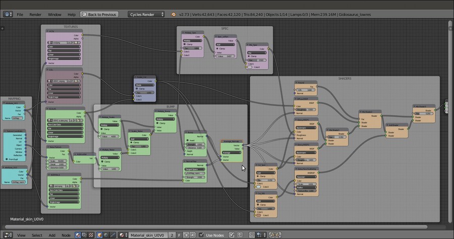
The total skin material network
- From step 1 to step 18 we built the SHADERS part of the material, that is, the combination of the diffuse with the glossy component and the addition of the subsurface scattering effect.
- Note that the glossy component (the specularity) is obtained by mixing two glossy shaders with different roughness values; by setting the factor value of the Mix Shader1 node to 0.350, we give prevalence to the Glossy BSDF1 node effect, which is to the node connected to the first top Shader input socket.
- Also, we added the subsurface scattering effect by the Add Shader node, and to further tweak the blending of the effect with the rest of the shader, we added the Mix Shader3 node, to give prevalence to the output of the Mix Shader2 node (that is the output of the diffuse plus the glossy components).
- From step 19 to step 24 we saw some not mandatory but useful tips for assigning colors to the nodes, in order to visually distinguish and/or group them and make the whole material network more easily readable.
- At step 25 we started to add the textures, first the diffuse color one and then the grayscale scales image that we used here to add details to the coloration (and later for the bump effect). By mixing the scales with the diffuse color through the MixRGB node set to a Divide blend type, we automatically obtained a scales pattern on the skin itself.
- From step 30 to step 33 we tweaked the diffuse color map to also affect the glossy and the subsurface scattering components, but with different hues.
- Note that at step 34 we used an Attribute node to set the UV coordinates layer to be used for the mapping of the textures. It would have been unnecessary in this case, with the UVMap coordinates layer being the first one and therefore the default one. Cycles, in fact, in the case of image textures, automatically uses any existing UV coordinates layer. But, because later we also used a different UV coordinates layer, it was better to specify it.
- From step 35 to step 38 we improved the glossiness effect of the skin, by using the output of the
vcol.pngimage we had previously baked and tweaked through the nodes inside the SPEC frame. - From step 39 to step 47 we built the BUMP effect, by using the output of the SCALES image texture added through a MixRGB node to the output of a procedural Noise Texture. The RGB to BW node simply converts the colored output of the procedural noise to a grayscale output (and if you think we could have used the Fac output instead, well, it's not the same thing), and the Multiply_Scales and Multiply_Noise nodes set the strength of the outputs before the adding process. Through the Multiply_Bump node we also added the grayscale output of the combined bump to the glossy component.
- From step 48 to step 52 we also added the effect of the normal map we baked from the sculpted high resolution Gidiosaurus mesh to the bump pattern. The normal map is averaged, through the Vector Math node, with the bump output. Because of this averaging, the strength value of the normal map had to be set to double (2.000) to have full effect.
Still focusing on the character's head, there is a material we can obtain from the skin material with some modification, the material for the wet parts of the character's skin (inner eyelids, tongue, inner nostrils).
Going on from the previously saved file:
- If you think this is the case, especially if your computer (like mine) isn't very powerful, temporarily disable the Rendered preview by moving the mouse cursor inside the 3D viewport and pressing Shift + Z.
- In the Material window, click on the
Material_wet_U0V0material to select it. - Put the mouse pointer inside the Node Editor window, select the default two nodes already assigned to the material and delete them by pressing the X key.
- Now, in the Material window, re-select the
Material_skin_U0V0; put the mouse in the Node Editor window, press A twice to select everything, and press Ctrl + C. - Re-select the
Material_wet_U0V0, put the mouse pointer inside the empty Node Editor window and press Ctrl + V to paste the copied material nodes.Now we have copied the nodes of the skin material to the material assigned to the parts that need to appear wet; it's enough now to tweak this material a bit to modify the bump pattern and the glossiness:
- In the Node Editor, zoom to the Noise Texture node inside the BUMP frame; left-click on it to select it and then press the X key to delete it.
- Press Shift + A and add a Voronoi Texture node (Shift + A | Texture | Voronoi Texture); left-click on the node and, by keeping the mouse button pressed, move the node a little bit on the frame, so it should automatically be parented to it.
- Connect the Object output of the Texture Coordinate node to the Vector input socket of the Voronoi Texture node and the Color output of this latter node to the RGB to BW node input socket; set the Voronoi Scale to 200.000.
- Add an Invert node (Shift + A | Color | Invert) and paste it between the Voronoi Texture and the RGB to BW nodes:

The different texture nodes of the "Material_wet_U0V0"
- Scroll the Node Editor window a bit to the right to find the Multiply_Noise node: change the label to Multiply_Voronoi and the second Value to 0.025.
- Find the Scales_Col node and change Blend Type from Divide to Multiply.
- Now go to the SHADERS frame; change the IOR value of the Fresnel node to 15.000 and connect its output to the Fac input socket of the Mix Shader1 node; change the Distribution of both the Glossy BSDF1 and Glossy BSDF2 nodes to Ashikhmin-Shirley and set the Roughness of the Glossy BSDF2 node to 0.600.
We substituted the Noise Texture node with a Voronoi Texture node to give a kind of organic look to the surface of the tongue of the creature.
In the following screenshot, we can see the result of the wet material; note that for the occasion I opened the mouth wide, to make the inside more visible:

The rendered wet material
One more material we are going to create in this section of the recipe is the Material_enamels for teeth and talons; in this case, we just need mostly the SHADERS frame's nodes with the single contribution of the color image texture
U0V0_col.png, here using the UVMap2 coordinates layer to avoid having to create 5 different materials for the talons alone (originally distributed in different tiles). By the way, nothing is stopping you from creating several talon materials, if you prefer. - Again, select, copy and paste the skin material to the enamels material slot through the Node Editor window, as we have already done in steps 3, 4 and 5.
- This time, just delete the unnecessary nodes, in short keeping only the Attribute node, the COL node and the SHADERS frame with its parented nodes.
- Change the UV coordinates layer in the Name slot of the Attribute node to UVMap2 (and the label to Attribute_UV3). Lower the Roughness value of the Diffuse BSDF node to 0.000.
- Go to the SHADERS frame; select and delete the Col_Spec and Col_SSS nodes, then connect the Color output of the COL node also to the Color input socket of the Subsurface Scattering node.
- Select and delete the Glossy BSDF1 and the Glossy BSDF2 nodes.
- Add 2 Anisotropic BSDF shader nodes (Shift + A | Shader | Anisotropic BSDF), a Tangent node (Shift + A | Input | Tangent) and detach the Add Shader node from the Mix Shader3 node.
- Label the two Anisotropic BSDF shader nodes as Anisotropic BSDF1 and Anisotropic BSDF2 and connect them to the two Shader input sockets of the Add Shader node. Connect the output of the Tangent node to the Tangent input sockets of the two Anisotropic shader nodes.
- Set the Tangent of the Tangent node to Z. Set the Anisotropy of both the Anisotropic nodes to 0.500, the Roughness of the Anisotropic BSDF1 node to 0.500 and the Roughness of the Anisotropic BSDF2 node to 0.200.
- Connect the Add Shader output to both the second Shader input sockets of the Mix Shader1 and Mix Shader2 nodes.
- Set the IOR value of the Fresnel node to 1.540 and connect the Fresnel output to the Fac input sockets of the Mix Shader1, Mix Shader2, and Mix Shader3 nodes.
- Connect the output of the Diffuse BSDF shader node to the first Shader input socket of the Mix Shader1 node, then connect the output of the Mix Shader1 node to the first Shader input socket of the Mix Shader2 node.
- Connect the output of the Subsurface Scattering node to the second Shader input socket of the Mix Shader3 node.
- In the Subsurface Scattering node, change the Scale to 0.020 and the Radius to R 1.000, G 0.400, B 0.100.

The "Material_enamels" network
- Save the file.
Thanks to the two Anisotropic shaders with their different roughness values, we obtained a nice specularity effect along the length of the teeth (and therefore also of the talons):
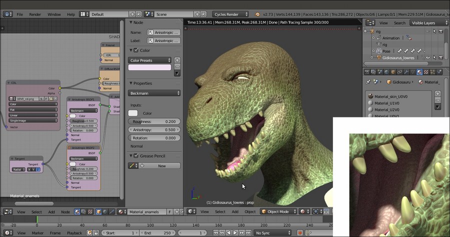
The rendered preview of the teeth (and talons) shader
- Shameless self-promotion—one other cookbook, published by Packt Publishing, explaining the logic behind Cycles materials and textures and with several material recipes (https://www.packtpub.com/hardware-and-creative/blender-cycles-materials-and-textures-cookbook-third-edition)
- The online documentation (http://wiki.blender.org/index.php/Doc:2.6/Manual/Render/Cycles/Nodes)
Getting ready
But first, as usual, we must prepare the file:
- As the very first step, go to the
texture_makingfolder and move the texturesvcol.png,vcol2.png,norm.png, andnorm2.pngto thetexturesfolder. - Then start Blender and open the
Gidiosaurus_baking_normals.blendfile we saved in Chapter 11, Refining the Textures. - Switch the left UV/Image Editor window with a Node Editor window and press the N key to get rid of the Properties sidebar. Put the mouse pointer in the 3D viewport to the right and press the T key to get rid of the Tool Shelf panel, then press the Z key twice to go in Solid viewport shading mode.
- Enable the 3rd scene layer, select and delete the Armor_detailing object (press the X key, then left-click to confirm).
- Enable the 4th scene layer and select and delete the Gidiosaurus_for_baking object as well. Enable the 14th scene layer, and also select and delete the Gidiosaurus_detailing and the enamels objects.
- Enable the 11th scene layer and right-click on the Gidiosaurus_lowres object to select it.
- It's not mandatory but, in case it is not already disabled, it is best to go to the Object Modifiers window and disable the Armature modifier visibility in the viewport by clicking on the eye icon button.
- Go to the UV Maps subpanel under the Object Data window and select the UVMap coordinates layer (the first one); press Tab to enter Edit Mode, then click on the + icon button to the right side of the UV Maps subpanel to add a new coordinates layer; rename it UVMap2.
- Go to the left window and change it into a UV/Image Editor; one by one, select the UV islands of the talons (at the moment these are placed inside the other UDIM tile spaces), and move them to the default U0V0 tile, to overlap the location of the teeth islands. The reason for this will be clear later, when we will reuse the same color map both for the teeth and for all the talons.
- If necessary, remember to disable the Keep UV and edit mode mesh selection in sync button on the UV/Image Editor toolbar:
Moving the talon islands to overlap the teeth islands inside the default U0V0 tile space
- Go out of Edit Mode and switch the UV/Image Editor window back to a Node Editor window.
- Click on the Engine to use for rendering slot on the main top header to switch to the Cycles Render engine.
- Also, enable the 6th scene layer to show the Lamps. Go to the Outliner, unhide and delete the Lamp.001 object and select the Lamp object; in the Object Data window, change the type to Spot and then click on the Use Nodes button. Set the Strength to 10.000 and the Color to R 1.000, G 1.000, B 0.650, then set the Size to 0.500 and enable the Multiple Importance item (the Multiple Importance Sampling helps in reducing noise for big lamps and sharp glossy reflections, at the cost of the samples rendering a bit slower).
- Put the mouse pointer in the 3D viewport and press N to call the Properties sidepanel; in the top Transform subpanel, type: Location X = 6.059204, Y = -9.912249 and Z = 7.546275, and Rotation X = 55.788944°, Y = 0° and Z = 30.561825°.
- Go to the Render window and, under the Sampling subpanel, set the Samples to 400 for Render and 300 for Preview.
- Go down to the Light Paths subpanel and disable the Reflective Caustics item, then set Filter Glossy to 1.000.
- Re-select the Gidiosaurus_lowres object and go to the Material window:
The 5 materials under the Cycles render engine
As you can see in the previous screenshot, the Gidiosaurus_lowres object has already assigned the 5 materials corresponding to the 5 UDIM tile spaces (see Chapter 5, Unwrapping the Low Resolution Mesh, and Chapter 10, Creating the Textures).
The materials have been created under Blender Internal so, switching to Cycles, they show but aren't initialized as node materials yet; besides this, just before starting the creation of the first Cycles material, we must add two more materials.
- Click the + icon button twice (Add a new material slot) to the right side of the Material window to add two new material slots.
- Select the penultimate slot and click on the New button; rename the new material as
Material_enamels. Select the last slot, click on the New button and rename it asMaterial_wet_U0V0. - Press Tab to enter Edit Mode and select all the vertices of the teeth and the talons; assign them to the
Material_enamelsslot. - Zoom on the Gidiosaurus head; select the vertices of the inner nostrils, of the inner edges of the eyelids and of the tongue, as shown in the following screenshot, and assign them to the
Material_wet_U0V0slot:Selecting the vertices of the "wet" areas of the character's head to assign them to the "Material_wet_U0V0" slot
- Save the file as
Gidiosaurus_shaders_start.blendfile.
We know that the skin of our character is shared in 5 different materials; we are going to focus on the head (Material_U0V0), as the more representative one.
Once we are happy with the result, we will also copy (with all the due differences) the material to the other body parts.
Therefore, the steps are as follows:
- In the materials list inside the Material window, select the
Material_U0V0(the first top one) and press Ctrl + left-click on it to rename it asMaterial_skin_U0V0; then, move down and click on the Use Nodes button inside the Surface subpanel.Immediately, a Diffuse BSDF shader node (already connected to a Material Output node) appears inside the Node Editor window to the left of the screen and listed in the Surface slot inside the Surface subpanel to the right:
The Diffuse BSDF shader node connected to the Material Output node
- In the Surface subpanel, under the Material window, click on the Surface slot that now shows the Diffuse BSDF shader: in the pop-up menu that appears, select a Mix Shader node:
Switching the Diffuse BSDF shader node with a Mix Shader node through the Material window drop-down list
The Surface slot now shows the Mix Shader node item, and right below there are two new Shader slots that at the moment show the None item; in fact, looking at the nodes inside the Node Editor window, we see that the Diffuse BSDF shader node has been replaced by a Mix Shader node, and that the two (green) Shader input sockets are still empty:
The Mix Shader node with its two shader input sockets in the UV/Image Editor window and in the Material window
- Click on the first Shader slot under the Surface subpanel to select, again from the pop-up menu, a Diffuse BSDF shader node; click on the second Shader slot and select a Mix Shader node; both the two new nodes are added and connected to the proper input socket, as we can see in the Node Editor window:
Two new nodes connected to the two shader input sockets of the Mix Shader node
At this point, to avoid confusion, it's already better to start to label the various nodes with meaningful names.
- Put the mouse pointer inside the Node Editor window and press the N key to call the Properties sidepanel.
- Select the last Mix Shader node we added to the material and then go to click on the Label slot inside the top Name subpanel of the side Properties panel: type Mix Shader1:
Labeling the nodes
- Select the other Mix Shader node (the old one) and repeat the procedure by labeling it as Mix Shader2:
Labeling the nodes again
- Put the mouse pointer on the 3D viewport and press the 0 key on the numpad to enter the Camera view.
- Press Shift + B and by left-clicking draw a box around the head of the Gidiosaurus character to crop the area that can be rendered.
- Zoom to the red square by scrolling the mouse wheel and then press Shift + Z to switch the Viewport Shading mode to Rendered:
Cropping the renderable area and zooming to it
- Put the mouse pointer inside the Node Editor window and press Shift + A. In the pop-up panel that appears, navigate to Shader and then click on the Glossy BSDF item to add the node; as it appears, move the mouse to place it to the left side of the Mix Shader1 node.
- Label it as Glossy BSDF1, connect its output to the first top Shader input socket of the Mix Shader1 node, and set Distribution to Beckmann:
Adding a Glossy BSDF shader node and labeling it
- Add a second Glossy BSDF shader node (Shift + A | Shader | Glossy BSDF) and place it right under the previous one; label it as Glossy BSDF2, connect its output to the second Shader input socket of the Mix Shader1 node, and set Distribution to Beckmann as well and the Roughness to 0.400.
- Set the factor value (Fac) of the Mix Shader1 node to 0.350:
Adding a second Glossy shader node and blending it with the first one through the Fac value of the Mix Shader1 node
- Add a Fresnel node (Shift + A | Input | Fresnel) and connect its Fac output to the Fac input socket of the Mix Shader2 node; set the IOR value to 3.840. Set the Roughness value of the Diffuse BSDF shader node to 0.500:
Adding a Fresnel node to set the Index of Refraction value to blend the diffuse with the glossy components
- Add a Subsurface Scattering node (Shift + A | Shader | Subsurface Scattering) and an Add Shader node (Shift + A | Shader | Add Shader). Move this last one to the link that connects the Mix Shader2 node to the Material Output node in order to paste it automatically between the two nodes (automatically when the connection line becomes highlighted):
Automatically joining the Add Shader node
- Connect the output of the Subsurface Scattering node to the second Shader input socket of the Add Shader node. In the SSS node, change Fallof from Cubic to Gaussian, set the Scale to 0.001 and click on the Radius button to set the RGB to 9.436, 3.348 and 1.790:
Connecting and setting the SSS node
- Add a new Mix Shader node (Shift + A | Shader | Mix Shader) and label it as Mix Shader3. Connect the output of the Mix Shader2 node to the first Shader input socket of the Mix Shader3 node, and the output of the Add Shader node to its second Shader input socket. Set the Fac of the Mix Shader3 node to 0.250 and connect its output to the Surface input socket of the Material Output node:
A little trick to tweak the influence of the Add shader node
- Add a Frame (Shift + A | Layout | Frame), box-select all the nodes (except the Material Output node) and then press Ctrl + P to parent them to the frame; label the frame as SHADERS.
- Select the SHADERS frame and go to the Properties sidepanel. Expand the Color subpanel (right under the Node subpanel) by clicking on the little horizontal black arrow, and enable the Color checkbox.
- Click on the color slot and set a light color of your choice (I set it to RGB 1.000, which is totally white). Then click on the + icon button to the side and in the Name slot of the Add Node Color Preset pop-up panel, write Frame, then click the big OK button.
- Select the Material Output node and then Shift-select the Frame again, then go to the Color subpanel and click on the big vertical arrow under the + and – icon buttons to the side. Click on the Copy Color item to copy the color of the Frame to the Material Output node:
The SHADERS frame with the nodes and the Copy Color tool under the N sidepanel
- Select any one of the other nodes, for example the Fresnel node, enable the Color checkbox and set a new color of your choice (for these nodes, I set it to R 1.000, G 0.819, B 0.617, which is a light brown).
- Click on the + icon button to the side and in the Name slot of the Add Node Color Preset pop-up panel, write Shaders, then click the big OK button.
- Now box-select all the other nodes inside the frame and click on the Copy Color item to copy the color from the Fresnel node to all the other selected nodes at once:
Copying the label color from one node to all the other selected nodes
At this point we have completed the basic shader for the skin; what we have to do now is to add the textures we painted in both Chapter 10, Creating the Textures, and Chapter 11, Refining the Textures.
So:
- Put the mouse pointer into the Node Editor window and add an Image Texture node (Shift + A | Texture | Image Texture); label it as COL and then use Shift + D to duplicate it; move the duplicated one down and change its label to SCALES.
As you label the newly added nodes, also assign colors to them to make them more easily readable inside the Node Editor window, and save these colors as presets as we did at step 20.
- Click on the Open button of the COL node and browse to the
texturesfolder. There, load the imageU0V0_col.png. - Click on the Open button of the SCALES node and browse to the
texturesfolder. There, load the imageU0V0_scales.png; set the Color Space to Non-Color Data. - Add a MixRGB node (Shift + A | Color | MixRGB) and label it as Scales_Col; connect the Color output of the COL node to the Color1 input socket of the Scales_Col node and the Color output of the SCALES node to its Color2 input socket. Set the Fac to 1.000 and the Blend Type to Divide.
- Connect the output of the Scales_Col node to the Color input socket of the Diffuse BSDF shader node inside the SHADERS frame.
The result so far is visible in the real-time rendered preview to the right:
The rendered result of the two combined image texture nodes
As you can see, the glossy component is strong in this one! We must lessen the effect, to obtain a more natural look.
- Add a new MixRGB node (Shift + A | Color | MixRGB) and label it as Col_Spec; set the Color2 to R 0.474, G 0.642, B 0.683, then also connect the output of the Scales_Col node to the Color1 input socket of the Col_Spec node.
- Set the Fac value to 0.150 and the Blend Type to Add, then connect its output to the Color input sockets of both the Glossy BSDF1 and Glossy BSDF2 nodes:
Varying the textures color output for the glossy component
- Press Shift + D to duplicate the Col_Spec node and label the duplicate as Col_SSS; set the Fac value to 1.000 and the Color2 to R 0.439, G 0.216, B 0.141. Connect the Color output of the Scales_Col node to the Color1 input socket of the Col_SSS node and the output of this latter node to the Color input socket of the Subsurface Scattering node; increase its Texture Blur to the maximum value.
- Shift-select the Col_Spec and the Col_SSS nodes and then also the SHADERS frame, and press Ctrl + P to parent them:
Varying the textures color output also for the SSS node
The new result looks a lot better:
A better result
- Add an Attribute node (Shift + A | Input | Attribute) and label it as Attribute_UV1. Connect its Vector output to the Vector input sockets of the COL and SCALES nodes and in the name field type UVMap:
Adding the Attribute node to establish the UV coordinates layer to be used
By the way, the glossy component is still a little unnatural.
- Add a new Image Texture node (Shift + A | Texture | Image Texture) and label it as VCOL. Click on the Open button, browse to the
texturefolder and load the imagevcol.png. - Press Shift + D to duplicate the Attribute node, change the label to Attribute_UV2, and change the Name field to UVMap_norm. Connect its Vector output to the Vector input of the VCOL node.
- Add a Math node (Shift + A | Converter | Math) and a MixRGB node (Shift + A | Color | MixRGB); connect the Color output of the VCOL node to the first Value input socket of the Math node; label this one as Spec_soften and set the second Value to 0.007. Connect its Value output to the Color1 input socket of the MixRGB node, which is now labeled as Mix_Spec.
- Connect the Color output of the Mix_Spec node to the Roughness input socket of the Glossy BSDF1 node:
Using the baked Vertex Color image to "soften" the character's skin specularity
The specularity is now a bit more realistic:
And the rendered result of this operation
Anyway, it's still missing the contribution of the bump effect.
- Add a Bump node (Shift + A | Vector | Bump); connect the output of the SCALES node to the Height input socket of the Bump node and the Normal output of this latter node to the Normal input socket of the Diffuse BSDF, Glossy BSDF1, Glossy BSDF2, and Subsurface Scattering nodes. Set the Strength of the Bump node to 0.500:
Adding the bump pattern to the shaders
Now we start to see something!
The bump effect in the rendered preview
By the way, the bump pattern is too even and, therefore, unrealistic; we must therefore break it in some way.
- Add a Noise Texture node (Shift + A | Texture | Noise Texture) and a Texture Coordinate node (Shift + A | Input | Texture Coordinate). Connect the Object output of the Texture Coordinate node to the Vector input socket of the Noise Texture node, then set the Scale of the texture to 50.000.
- Add a Math node (Shift + A | Converter | Math) and a MixRGB node (Shift + A | Color | MixRGB). Connect the Color output of the SCALES node to the Color1 input socket of the MixRGB node, and the Color output of the Noise Texture to the Color2 input socket.
- Set the MixRGB blend type to Add, the Fac value to 1.000 and label it as Scales_Noise. To see the effect, connect its Color output to the Height input socket of the Bump node (but this is going to change very soon, so it's not mandatory at this step):
Adding some noise to the bump pattern part 1
- Select the Math node and move it on the link connecting the Noise Texture node with the Scales_Noise node to paste it in between them: set the Operation to Multiply, the second Value to 1.000, and label it as Multiply_Noise.
- Press Shift + D to duplicate the Multiply_Noise node, change the label to Multiply_Scales and the second Value to 4.000; paste it between the SCALES node and the Scales_Noise node.
- Add an RGB to BW node (Shift + A | Converter | RGB to BW) and paste it between the Noise Texture node and the Multiply_Noise one:
Adding some noise to the bump pattern part 2
- Press Shift + D to duplicate the Multiply_Scales node and change the duplicate label to Multiply_Bump; connect the output of the Multiply_Scales to the first Value input socket of the Multiply_Bump node and the output of the Scales_Noise node to the second Value input socket. Connect the output of the Multiply_Bump node to the Height input socket of the Bump node:
Adding some noise to the bump pattern part 3
- Add a MixRGB node (Shift + A | Color | MixRGB) and paste it between the VCOL node and the Spec_soften node; label it as Multiply_Spec, set the Blend Type to Multiply and the Fac value to 0.850; connect the output of the Multiply_Bump node to the Color2 input socket of the Multiply_Spec node:
Modulating the specularity with the aid of the bump pattern output
The overall bump effect is almost completed:
The new Rendered bump effect
What is still missing now is the normal map we obtained from the sculpted Gidiosaurus mesh in Chapter 11, Refining the Textures.
- Add a new Image Texture node (Shift + A | Texture | Image Texture) and a Normal Map node (Shift + A | Vector | Normal Map). Label the Image Texture node as NORMALS, then connect the Vector output of the Attribute_UV2 node to the Vector input socket of the NORMALS node.
- Connect the Color output of the NORMALS node to the Color input socket of the Normal Map node, then click on the Open button on the NORMALS node, browse to the
texturesfolder and load the imagenorm.png. Set the Color Space of the NORMALS node to Non-Color Data and click on the empty slot in the Normal Map node to select the UVMap_norm coordinates layer. - Add a Vector Math node (Shift + A | Converter | Vector Math), label it as Average_Normals and paste it right after the Bump node; connect the output of the Normal Map node to the second Value input socket of the Average_Normals node.
- Set the Operation of the Average_Normals node to Average and connect its Vector output to the Vector input sockets of the Diffuse BSDF, Glossy BSDF1, Glossy BSDF2, and Subsurface Scattering nodes.
- Set the Strength of the Normal Map to 2.000:
Adding the normal map output to the bump pattern
Finally we have completed the first skin material!
The completed Material_skin_U0V0
- Save the file as
Gidiosaurus_skin_Cycles.blend.
This material can at first glance appear a bit complex, but actually the design behind it is quite simple as you can see in the following screenshot, where each component has been visually grouped by colors and frames (open the provided Gidiosaurus_skin_Cycles_01.blend file to have a better look):
The total skin material network
- From step 1 to step 18 we built the SHADERS part of the material, that is, the combination of the diffuse with the glossy component and the addition of the subsurface scattering effect.
- Note that the glossy component (the specularity) is obtained by mixing two glossy shaders with different roughness values; by setting the factor value of the Mix Shader1 node to 0.350, we give prevalence to the Glossy BSDF1 node effect, which is to the node connected to the first top Shader input socket.
- Also, we added the subsurface scattering effect by the Add Shader node, and to further tweak the blending of the effect with the rest of the shader, we added the Mix Shader3 node, to give prevalence to the output of the Mix Shader2 node (that is the output of the diffuse plus the glossy components).
- From step 19 to step 24 we saw some not mandatory but useful tips for assigning colors to the nodes, in order to visually distinguish and/or group them and make the whole material network more easily readable.
- At step 25 we started to add the textures, first the diffuse color one and then the grayscale scales image that we used here to add details to the coloration (and later for the bump effect). By mixing the scales with the diffuse color through the MixRGB node set to a Divide blend type, we automatically obtained a scales pattern on the skin itself.
- From step 30 to step 33 we tweaked the diffuse color map to also affect the glossy and the subsurface scattering components, but with different hues.
- Note that at step 34 we used an Attribute node to set the UV coordinates layer to be used for the mapping of the textures. It would have been unnecessary in this case, with the UVMap coordinates layer being the first one and therefore the default one. Cycles, in fact, in the case of image textures, automatically uses any existing UV coordinates layer. But, because later we also used a different UV coordinates layer, it was better to specify it.
- From step 35 to step 38 we improved the glossiness effect of the skin, by using the output of the
vcol.pngimage we had previously baked and tweaked through the nodes inside the SPEC frame. - From step 39 to step 47 we built the BUMP effect, by using the output of the SCALES image texture added through a MixRGB node to the output of a procedural Noise Texture. The RGB to BW node simply converts the colored output of the procedural noise to a grayscale output (and if you think we could have used the Fac output instead, well, it's not the same thing), and the Multiply_Scales and Multiply_Noise nodes set the strength of the outputs before the adding process. Through the Multiply_Bump node we also added the grayscale output of the combined bump to the glossy component.
- From step 48 to step 52 we also added the effect of the normal map we baked from the sculpted high resolution Gidiosaurus mesh to the bump pattern. The normal map is averaged, through the Vector Math node, with the bump output. Because of this averaging, the strength value of the normal map had to be set to double (2.000) to have full effect.
Still focusing on the character's head, there is a material we can obtain from the skin material with some modification, the material for the wet parts of the character's skin (inner eyelids, tongue, inner nostrils).
Going on from the previously saved file:
- If you think this is the case, especially if your computer (like mine) isn't very powerful, temporarily disable the Rendered preview by moving the mouse cursor inside the 3D viewport and pressing Shift + Z.
- In the Material window, click on the
Material_wet_U0V0material to select it. - Put the mouse pointer inside the Node Editor window, select the default two nodes already assigned to the material and delete them by pressing the X key.
- Now, in the Material window, re-select the
Material_skin_U0V0; put the mouse in the Node Editor window, press A twice to select everything, and press Ctrl + C. - Re-select the
Material_wet_U0V0, put the mouse pointer inside the empty Node Editor window and press Ctrl + V to paste the copied material nodes.Now we have copied the nodes of the skin material to the material assigned to the parts that need to appear wet; it's enough now to tweak this material a bit to modify the bump pattern and the glossiness:
- In the Node Editor, zoom to the Noise Texture node inside the BUMP frame; left-click on it to select it and then press the X key to delete it.
- Press Shift + A and add a Voronoi Texture node (Shift + A | Texture | Voronoi Texture); left-click on the node and, by keeping the mouse button pressed, move the node a little bit on the frame, so it should automatically be parented to it.
- Connect the Object output of the Texture Coordinate node to the Vector input socket of the Voronoi Texture node and the Color output of this latter node to the RGB to BW node input socket; set the Voronoi Scale to 200.000.
- Add an Invert node (Shift + A | Color | Invert) and paste it between the Voronoi Texture and the RGB to BW nodes:
The different texture nodes of the "Material_wet_U0V0"
- Scroll the Node Editor window a bit to the right to find the Multiply_Noise node: change the label to Multiply_Voronoi and the second Value to 0.025.
- Find the Scales_Col node and change Blend Type from Divide to Multiply.
- Now go to the SHADERS frame; change the IOR value of the Fresnel node to 15.000 and connect its output to the Fac input socket of the Mix Shader1 node; change the Distribution of both the Glossy BSDF1 and Glossy BSDF2 nodes to Ashikhmin-Shirley and set the Roughness of the Glossy BSDF2 node to 0.600.
We substituted the Noise Texture node with a Voronoi Texture node to give a kind of organic look to the surface of the tongue of the creature.
In the following screenshot, we can see the result of the wet material; note that for the occasion I opened the mouth wide, to make the inside more visible:
The rendered wet material
One more material we are going to create in this section of the recipe is the Material_enamels for teeth and talons; in this case, we just need mostly the SHADERS frame's nodes with the single contribution of the color image texture
U0V0_col.png, here using the UVMap2 coordinates layer to avoid having to create 5 different materials for the talons alone (originally distributed in different tiles). By the way, nothing is stopping you from creating several talon materials, if you prefer. - Again, select, copy and paste the skin material to the enamels material slot through the Node Editor window, as we have already done in steps 3, 4 and 5.
- This time, just delete the unnecessary nodes, in short keeping only the Attribute node, the COL node and the SHADERS frame with its parented nodes.
- Change the UV coordinates layer in the Name slot of the Attribute node to UVMap2 (and the label to Attribute_UV3). Lower the Roughness value of the Diffuse BSDF node to 0.000.
- Go to the SHADERS frame; select and delete the Col_Spec and Col_SSS nodes, then connect the Color output of the COL node also to the Color input socket of the Subsurface Scattering node.
- Select and delete the Glossy BSDF1 and the Glossy BSDF2 nodes.
- Add 2 Anisotropic BSDF shader nodes (Shift + A | Shader | Anisotropic BSDF), a Tangent node (Shift + A | Input | Tangent) and detach the Add Shader node from the Mix Shader3 node.
- Label the two Anisotropic BSDF shader nodes as Anisotropic BSDF1 and Anisotropic BSDF2 and connect them to the two Shader input sockets of the Add Shader node. Connect the output of the Tangent node to the Tangent input sockets of the two Anisotropic shader nodes.
- Set the Tangent of the Tangent node to Z. Set the Anisotropy of both the Anisotropic nodes to 0.500, the Roughness of the Anisotropic BSDF1 node to 0.500 and the Roughness of the Anisotropic BSDF2 node to 0.200.
- Connect the Add Shader output to both the second Shader input sockets of the Mix Shader1 and Mix Shader2 nodes.
- Set the IOR value of the Fresnel node to 1.540 and connect the Fresnel output to the Fac input sockets of the Mix Shader1, Mix Shader2, and Mix Shader3 nodes.
- Connect the output of the Diffuse BSDF shader node to the first Shader input socket of the Mix Shader1 node, then connect the output of the Mix Shader1 node to the first Shader input socket of the Mix Shader2 node.
- Connect the output of the Subsurface Scattering node to the second Shader input socket of the Mix Shader3 node.
- In the Subsurface Scattering node, change the Scale to 0.020 and the Radius to R 1.000, G 0.400, B 0.100.
The "Material_enamels" network
- Save the file.
Thanks to the two Anisotropic shaders with their different roughness values, we obtained a nice specularity effect along the length of the teeth (and therefore also of the talons):
The rendered preview of the teeth (and talons) shader
- Shameless self-promotion—one other cookbook, published by Packt Publishing, explaining the logic behind Cycles materials and textures and with several material recipes (https://www.packtpub.com/hardware-and-creative/blender-cycles-materials-and-textures-cookbook-third-edition)
- The online documentation (http://wiki.blender.org/index.php/Doc:2.6/Manual/Render/Cycles/Nodes)
How to do it…
We know that the skin of our character is shared in 5 different materials; we are going to focus on the head (Material_U0V0), as the more representative one.
Once we are happy with the result, we will also copy (with all the due differences) the material to the other body parts.
Therefore, the steps are as follows:
- In the materials list inside the Material window, select the
Material_U0V0(the first top one) and press Ctrl + left-click on it to rename it asMaterial_skin_U0V0; then, move down and click on the Use Nodes button inside the Surface subpanel.Immediately, a Diffuse BSDF shader node (already connected to a Material Output node) appears inside the Node Editor window to the left of the screen and listed in the Surface slot inside the Surface subpanel to the right:
The Diffuse BSDF shader node connected to the Material Output node
- In the Surface subpanel, under the Material window, click on the Surface slot that now shows the Diffuse BSDF shader: in the pop-up menu that appears, select a Mix Shader node:
Switching the Diffuse BSDF shader node with a Mix Shader node through the Material window drop-down list
The Surface slot now shows the Mix Shader node item, and right below there are two new Shader slots that at the moment show the None item; in fact, looking at the nodes inside the Node Editor window, we see that the Diffuse BSDF shader node has been replaced by a Mix Shader node, and that the two (green) Shader input sockets are still empty:
The Mix Shader node with its two shader input sockets in the UV/Image Editor window and in the Material window
- Click on the first Shader slot under the Surface subpanel to select, again from the pop-up menu, a Diffuse BSDF shader node; click on the second Shader slot and select a Mix Shader node; both the two new nodes are added and connected to the proper input socket, as we can see in the Node Editor window:
Two new nodes connected to the two shader input sockets of the Mix Shader node
At this point, to avoid confusion, it's already better to start to label the various nodes with meaningful names.
- Put the mouse pointer inside the Node Editor window and press the N key to call the Properties sidepanel.
- Select the last Mix Shader node we added to the material and then go to click on the Label slot inside the top Name subpanel of the side Properties panel: type Mix Shader1:
Labeling the nodes
- Select the other Mix Shader node (the old one) and repeat the procedure by labeling it as Mix Shader2:
Labeling the nodes again
- Put the mouse pointer on the 3D viewport and press the 0 key on the numpad to enter the Camera view.
- Press Shift + B and by left-clicking draw a box around the head of the Gidiosaurus character to crop the area that can be rendered.
- Zoom to the red square by scrolling the mouse wheel and then press Shift + Z to switch the Viewport Shading mode to Rendered:
Cropping the renderable area and zooming to it
- Put the mouse pointer inside the Node Editor window and press Shift + A. In the pop-up panel that appears, navigate to Shader and then click on the Glossy BSDF item to add the node; as it appears, move the mouse to place it to the left side of the Mix Shader1 node.
- Label it as Glossy BSDF1, connect its output to the first top Shader input socket of the Mix Shader1 node, and set Distribution to Beckmann:
Adding a Glossy BSDF shader node and labeling it
- Add a second Glossy BSDF shader node (Shift + A | Shader | Glossy BSDF) and place it right under the previous one; label it as Glossy BSDF2, connect its output to the second Shader input socket of the Mix Shader1 node, and set Distribution to Beckmann as well and the Roughness to 0.400.
- Set the factor value (Fac) of the Mix Shader1 node to 0.350:
Adding a second Glossy shader node and blending it with the first one through the Fac value of the Mix Shader1 node
- Add a Fresnel node (Shift + A | Input | Fresnel) and connect its Fac output to the Fac input socket of the Mix Shader2 node; set the IOR value to 3.840. Set the Roughness value of the Diffuse BSDF shader node to 0.500:
Adding a Fresnel node to set the Index of Refraction value to blend the diffuse with the glossy components
- Add a Subsurface Scattering node (Shift + A | Shader | Subsurface Scattering) and an Add Shader node (Shift + A | Shader | Add Shader). Move this last one to the link that connects the Mix Shader2 node to the Material Output node in order to paste it automatically between the two nodes (automatically when the connection line becomes highlighted):
Automatically joining the Add Shader node
- Connect the output of the Subsurface Scattering node to the second Shader input socket of the Add Shader node. In the SSS node, change Fallof from Cubic to Gaussian, set the Scale to 0.001 and click on the Radius button to set the RGB to 9.436, 3.348 and 1.790:
Connecting and setting the SSS node
- Add a new Mix Shader node (Shift + A | Shader | Mix Shader) and label it as Mix Shader3. Connect the output of the Mix Shader2 node to the first Shader input socket of the Mix Shader3 node, and the output of the Add Shader node to its second Shader input socket. Set the Fac of the Mix Shader3 node to 0.250 and connect its output to the Surface input socket of the Material Output node:
A little trick to tweak the influence of the Add shader node
- Add a Frame (Shift + A | Layout | Frame), box-select all the nodes (except the Material Output node) and then press Ctrl + P to parent them to the frame; label the frame as SHADERS.
- Select the SHADERS frame and go to the Properties sidepanel. Expand the Color subpanel (right under the Node subpanel) by clicking on the little horizontal black arrow, and enable the Color checkbox.
- Click on the color slot and set a light color of your choice (I set it to RGB 1.000, which is totally white). Then click on the + icon button to the side and in the Name slot of the Add Node Color Preset pop-up panel, write Frame, then click the big OK button.
- Select the Material Output node and then Shift-select the Frame again, then go to the Color subpanel and click on the big vertical arrow under the + and – icon buttons to the side. Click on the Copy Color item to copy the color of the Frame to the Material Output node:
The SHADERS frame with the nodes and the Copy Color tool under the N sidepanel
- Select any one of the other nodes, for example the Fresnel node, enable the Color checkbox and set a new color of your choice (for these nodes, I set it to R 1.000, G 0.819, B 0.617, which is a light brown).
- Click on the + icon button to the side and in the Name slot of the Add Node Color Preset pop-up panel, write Shaders, then click the big OK button.
- Now box-select all the other nodes inside the frame and click on the Copy Color item to copy the color from the Fresnel node to all the other selected nodes at once:
Copying the label color from one node to all the other selected nodes
At this point we have completed the basic shader for the skin; what we have to do now is to add the textures we painted in both Chapter 10, Creating the Textures, and Chapter 11, Refining the Textures.
So:
- Put the mouse pointer into the Node Editor window and add an Image Texture node (Shift + A | Texture | Image Texture); label it as COL and then use Shift + D to duplicate it; move the duplicated one down and change its label to SCALES.
As you label the newly added nodes, also assign colors to them to make them more easily readable inside the Node Editor window, and save these colors as presets as we did at step 20.
- Click on the Open button of the COL node and browse to the
texturesfolder. There, load the imageU0V0_col.png. - Click on the Open button of the SCALES node and browse to the
texturesfolder. There, load the imageU0V0_scales.png; set the Color Space to Non-Color Data. - Add a MixRGB node (Shift + A | Color | MixRGB) and label it as Scales_Col; connect the Color output of the COL node to the Color1 input socket of the Scales_Col node and the Color output of the SCALES node to its Color2 input socket. Set the Fac to 1.000 and the Blend Type to Divide.
- Connect the output of the Scales_Col node to the Color input socket of the Diffuse BSDF shader node inside the SHADERS frame.
The result so far is visible in the real-time rendered preview to the right:
The rendered result of the two combined image texture nodes
As you can see, the glossy component is strong in this one! We must lessen the effect, to obtain a more natural look.
- Add a new MixRGB node (Shift + A | Color | MixRGB) and label it as Col_Spec; set the Color2 to R 0.474, G 0.642, B 0.683, then also connect the output of the Scales_Col node to the Color1 input socket of the Col_Spec node.
- Set the Fac value to 0.150 and the Blend Type to Add, then connect its output to the Color input sockets of both the Glossy BSDF1 and Glossy BSDF2 nodes:
Varying the textures color output for the glossy component
- Press Shift + D to duplicate the Col_Spec node and label the duplicate as Col_SSS; set the Fac value to 1.000 and the Color2 to R 0.439, G 0.216, B 0.141. Connect the Color output of the Scales_Col node to the Color1 input socket of the Col_SSS node and the output of this latter node to the Color input socket of the Subsurface Scattering node; increase its Texture Blur to the maximum value.
- Shift-select the Col_Spec and the Col_SSS nodes and then also the SHADERS frame, and press Ctrl + P to parent them:
Varying the textures color output also for the SSS node
The new result looks a lot better:
A better result
- Add an Attribute node (Shift + A | Input | Attribute) and label it as Attribute_UV1. Connect its Vector output to the Vector input sockets of the COL and SCALES nodes and in the name field type UVMap:
Adding the Attribute node to establish the UV coordinates layer to be used
By the way, the glossy component is still a little unnatural.
- Add a new Image Texture node (Shift + A | Texture | Image Texture) and label it as VCOL. Click on the Open button, browse to the
texturefolder and load the imagevcol.png. - Press Shift + D to duplicate the Attribute node, change the label to Attribute_UV2, and change the Name field to UVMap_norm. Connect its Vector output to the Vector input of the VCOL node.
- Add a Math node (Shift + A | Converter | Math) and a MixRGB node (Shift + A | Color | MixRGB); connect the Color output of the VCOL node to the first Value input socket of the Math node; label this one as Spec_soften and set the second Value to 0.007. Connect its Value output to the Color1 input socket of the MixRGB node, which is now labeled as Mix_Spec.
- Connect the Color output of the Mix_Spec node to the Roughness input socket of the Glossy BSDF1 node:
Using the baked Vertex Color image to "soften" the character's skin specularity
The specularity is now a bit more realistic:
And the rendered result of this operation
Anyway, it's still missing the contribution of the bump effect.
- Add a Bump node (Shift + A | Vector | Bump); connect the output of the SCALES node to the Height input socket of the Bump node and the Normal output of this latter node to the Normal input socket of the Diffuse BSDF, Glossy BSDF1, Glossy BSDF2, and Subsurface Scattering nodes. Set the Strength of the Bump node to 0.500:
Adding the bump pattern to the shaders
Now we start to see something!
The bump effect in the rendered preview
By the way, the bump pattern is too even and, therefore, unrealistic; we must therefore break it in some way.
- Add a Noise Texture node (Shift + A | Texture | Noise Texture) and a Texture Coordinate node (Shift + A | Input | Texture Coordinate). Connect the Object output of the Texture Coordinate node to the Vector input socket of the Noise Texture node, then set the Scale of the texture to 50.000.
- Add a Math node (Shift + A | Converter | Math) and a MixRGB node (Shift + A | Color | MixRGB). Connect the Color output of the SCALES node to the Color1 input socket of the MixRGB node, and the Color output of the Noise Texture to the Color2 input socket.
- Set the MixRGB blend type to Add, the Fac value to 1.000 and label it as Scales_Noise. To see the effect, connect its Color output to the Height input socket of the Bump node (but this is going to change very soon, so it's not mandatory at this step):
Adding some noise to the bump pattern part 1
- Select the Math node and move it on the link connecting the Noise Texture node with the Scales_Noise node to paste it in between them: set the Operation to Multiply, the second Value to 1.000, and label it as Multiply_Noise.
- Press Shift + D to duplicate the Multiply_Noise node, change the label to Multiply_Scales and the second Value to 4.000; paste it between the SCALES node and the Scales_Noise node.
- Add an RGB to BW node (Shift + A | Converter | RGB to BW) and paste it between the Noise Texture node and the Multiply_Noise one:
Adding some noise to the bump pattern part 2
- Press Shift + D to duplicate the Multiply_Scales node and change the duplicate label to Multiply_Bump; connect the output of the Multiply_Scales to the first Value input socket of the Multiply_Bump node and the output of the Scales_Noise node to the second Value input socket. Connect the output of the Multiply_Bump node to the Height input socket of the Bump node:
Adding some noise to the bump pattern part 3
- Add a MixRGB node (Shift + A | Color | MixRGB) and paste it between the VCOL node and the Spec_soften node; label it as Multiply_Spec, set the Blend Type to Multiply and the Fac value to 0.850; connect the output of the Multiply_Bump node to the Color2 input socket of the Multiply_Spec node:
Modulating the specularity with the aid of the bump pattern output
The overall bump effect is almost completed:
The new Rendered bump effect
What is still missing now is the normal map we obtained from the sculpted Gidiosaurus mesh in Chapter 11, Refining the Textures.
- Add a new Image Texture node (Shift + A | Texture | Image Texture) and a Normal Map node (Shift + A | Vector | Normal Map). Label the Image Texture node as NORMALS, then connect the Vector output of the Attribute_UV2 node to the Vector input socket of the NORMALS node.
- Connect the Color output of the NORMALS node to the Color input socket of the Normal Map node, then click on the Open button on the NORMALS node, browse to the
texturesfolder and load the imagenorm.png. Set the Color Space of the NORMALS node to Non-Color Data and click on the empty slot in the Normal Map node to select the UVMap_norm coordinates layer. - Add a Vector Math node (Shift + A | Converter | Vector Math), label it as Average_Normals and paste it right after the Bump node; connect the output of the Normal Map node to the second Value input socket of the Average_Normals node.
- Set the Operation of the Average_Normals node to Average and connect its Vector output to the Vector input sockets of the Diffuse BSDF, Glossy BSDF1, Glossy BSDF2, and Subsurface Scattering nodes.
- Set the Strength of the Normal Map to 2.000:
Adding the normal map output to the bump pattern
Finally we have completed the first skin material!
The completed Material_skin_U0V0
- Save the file as
Gidiosaurus_skin_Cycles.blend.
This material can at first glance appear a bit complex, but actually the design behind it is quite simple as you can see in the following screenshot, where each component has been visually grouped by colors and frames (open the provided Gidiosaurus_skin_Cycles_01.blend file to have a better look):
The total skin material network
- From step 1 to step 18 we built the SHADERS part of the material, that is, the combination of the diffuse with the glossy component and the addition of the subsurface scattering effect.
- Note that the glossy component (the specularity) is obtained by mixing two glossy shaders with different roughness values; by setting the factor value of the Mix Shader1 node to 0.350, we give prevalence to the Glossy BSDF1 node effect, which is to the node connected to the first top Shader input socket.
- Also, we added the subsurface scattering effect by the Add Shader node, and to further tweak the blending of the effect with the rest of the shader, we added the Mix Shader3 node, to give prevalence to the output of the Mix Shader2 node (that is the output of the diffuse plus the glossy components).
- From step 19 to step 24 we saw some not mandatory but useful tips for assigning colors to the nodes, in order to visually distinguish and/or group them and make the whole material network more easily readable.
- At step 25 we started to add the textures, first the diffuse color one and then the grayscale scales image that we used here to add details to the coloration (and later for the bump effect). By mixing the scales with the diffuse color through the MixRGB node set to a Divide blend type, we automatically obtained a scales pattern on the skin itself.
- From step 30 to step 33 we tweaked the diffuse color map to also affect the glossy and the subsurface scattering components, but with different hues.
- Note that at step 34 we used an Attribute node to set the UV coordinates layer to be used for the mapping of the textures. It would have been unnecessary in this case, with the UVMap coordinates layer being the first one and therefore the default one. Cycles, in fact, in the case of image textures, automatically uses any existing UV coordinates layer. But, because later we also used a different UV coordinates layer, it was better to specify it.
- From step 35 to step 38 we improved the glossiness effect of the skin, by using the output of the
vcol.pngimage we had previously baked and tweaked through the nodes inside the SPEC frame. - From step 39 to step 47 we built the BUMP effect, by using the output of the SCALES image texture added through a MixRGB node to the output of a procedural Noise Texture. The RGB to BW node simply converts the colored output of the procedural noise to a grayscale output (and if you think we could have used the Fac output instead, well, it's not the same thing), and the Multiply_Scales and Multiply_Noise nodes set the strength of the outputs before the adding process. Through the Multiply_Bump node we also added the grayscale output of the combined bump to the glossy component.
- From step 48 to step 52 we also added the effect of the normal map we baked from the sculpted high resolution Gidiosaurus mesh to the bump pattern. The normal map is averaged, through the Vector Math node, with the bump output. Because of this averaging, the strength value of the normal map had to be set to double (2.000) to have full effect.
Still focusing on the character's head, there is a material we can obtain from the skin material with some modification, the material for the wet parts of the character's skin (inner eyelids, tongue, inner nostrils).
Going on from the previously saved file:
- If you think this is the case, especially if your computer (like mine) isn't very powerful, temporarily disable the Rendered preview by moving the mouse cursor inside the 3D viewport and pressing Shift + Z.
- In the Material window, click on the
Material_wet_U0V0material to select it. - Put the mouse pointer inside the Node Editor window, select the default two nodes already assigned to the material and delete them by pressing the X key.
- Now, in the Material window, re-select the
Material_skin_U0V0; put the mouse in the Node Editor window, press A twice to select everything, and press Ctrl + C. - Re-select the
Material_wet_U0V0, put the mouse pointer inside the empty Node Editor window and press Ctrl + V to paste the copied material nodes.Now we have copied the nodes of the skin material to the material assigned to the parts that need to appear wet; it's enough now to tweak this material a bit to modify the bump pattern and the glossiness:
- In the Node Editor, zoom to the Noise Texture node inside the BUMP frame; left-click on it to select it and then press the X key to delete it.
- Press Shift + A and add a Voronoi Texture node (Shift + A | Texture | Voronoi Texture); left-click on the node and, by keeping the mouse button pressed, move the node a little bit on the frame, so it should automatically be parented to it.
- Connect the Object output of the Texture Coordinate node to the Vector input socket of the Voronoi Texture node and the Color output of this latter node to the RGB to BW node input socket; set the Voronoi Scale to 200.000.
- Add an Invert node (Shift + A | Color | Invert) and paste it between the Voronoi Texture and the RGB to BW nodes:
The different texture nodes of the "Material_wet_U0V0"
- Scroll the Node Editor window a bit to the right to find the Multiply_Noise node: change the label to Multiply_Voronoi and the second Value to 0.025.
- Find the Scales_Col node and change Blend Type from Divide to Multiply.
- Now go to the SHADERS frame; change the IOR value of the Fresnel node to 15.000 and connect its output to the Fac input socket of the Mix Shader1 node; change the Distribution of both the Glossy BSDF1 and Glossy BSDF2 nodes to Ashikhmin-Shirley and set the Roughness of the Glossy BSDF2 node to 0.600.
We substituted the Noise Texture node with a Voronoi Texture node to give a kind of organic look to the surface of the tongue of the creature.
In the following screenshot, we can see the result of the wet material; note that for the occasion I opened the mouth wide, to make the inside more visible:
The rendered wet material
One more material we are going to create in this section of the recipe is the Material_enamels for teeth and talons; in this case, we just need mostly the SHADERS frame's nodes with the single contribution of the color image texture
U0V0_col.png, here using the UVMap2 coordinates layer to avoid having to create 5 different materials for the talons alone (originally distributed in different tiles). By the way, nothing is stopping you from creating several talon materials, if you prefer. - Again, select, copy and paste the skin material to the enamels material slot through the Node Editor window, as we have already done in steps 3, 4 and 5.
- This time, just delete the unnecessary nodes, in short keeping only the Attribute node, the COL node and the SHADERS frame with its parented nodes.
- Change the UV coordinates layer in the Name slot of the Attribute node to UVMap2 (and the label to Attribute_UV3). Lower the Roughness value of the Diffuse BSDF node to 0.000.
- Go to the SHADERS frame; select and delete the Col_Spec and Col_SSS nodes, then connect the Color output of the COL node also to the Color input socket of the Subsurface Scattering node.
- Select and delete the Glossy BSDF1 and the Glossy BSDF2 nodes.
- Add 2 Anisotropic BSDF shader nodes (Shift + A | Shader | Anisotropic BSDF), a Tangent node (Shift + A | Input | Tangent) and detach the Add Shader node from the Mix Shader3 node.
- Label the two Anisotropic BSDF shader nodes as Anisotropic BSDF1 and Anisotropic BSDF2 and connect them to the two Shader input sockets of the Add Shader node. Connect the output of the Tangent node to the Tangent input sockets of the two Anisotropic shader nodes.
- Set the Tangent of the Tangent node to Z. Set the Anisotropy of both the Anisotropic nodes to 0.500, the Roughness of the Anisotropic BSDF1 node to 0.500 and the Roughness of the Anisotropic BSDF2 node to 0.200.
- Connect the Add Shader output to both the second Shader input sockets of the Mix Shader1 and Mix Shader2 nodes.
- Set the IOR value of the Fresnel node to 1.540 and connect the Fresnel output to the Fac input sockets of the Mix Shader1, Mix Shader2, and Mix Shader3 nodes.
- Connect the output of the Diffuse BSDF shader node to the first Shader input socket of the Mix Shader1 node, then connect the output of the Mix Shader1 node to the first Shader input socket of the Mix Shader2 node.
- Connect the output of the Subsurface Scattering node to the second Shader input socket of the Mix Shader3 node.
- In the Subsurface Scattering node, change the Scale to 0.020 and the Radius to R 1.000, G 0.400, B 0.100.
The "Material_enamels" network
- Save the file.
Thanks to the two Anisotropic shaders with their different roughness values, we obtained a nice specularity effect along the length of the teeth (and therefore also of the talons):
The rendered preview of the teeth (and talons) shader
- Shameless self-promotion—one other cookbook, published by Packt Publishing, explaining the logic behind Cycles materials and textures and with several material recipes (https://www.packtpub.com/hardware-and-creative/blender-cycles-materials-and-textures-cookbook-third-edition)
- The online documentation (http://wiki.blender.org/index.php/Doc:2.6/Manual/Render/Cycles/Nodes)
How it works…
This material can at first glance appear a bit complex, but actually the design behind it is quite simple as you can see in the following screenshot, where each component has been visually grouped by colors and frames (open the provided Gidiosaurus_skin_Cycles_01.blend file to have a better look):
The total skin material network
- From step 1 to step 18 we built the SHADERS part of the material, that is, the combination of the diffuse with the glossy component and the addition of the subsurface scattering effect.
- Note that the glossy component (the specularity) is obtained by mixing two glossy shaders with different roughness values; by setting the factor value of the Mix Shader1 node to 0.350, we give prevalence to the Glossy BSDF1 node effect, which is to the node connected to the first top Shader input socket.
- Also, we added the subsurface scattering effect by the Add Shader node, and to further tweak the blending of the effect with the rest of the shader, we added the Mix Shader3 node, to give prevalence to the output of the Mix Shader2 node (that is the output of the diffuse plus the glossy components).
- From step 19 to step 24 we saw some not mandatory but useful tips for assigning colors to the nodes, in order to visually distinguish and/or group them and make the whole material network more easily readable.
- At step 25 we started to add the textures, first the diffuse color one and then the grayscale scales image that we used here to add details to the coloration (and later for the bump effect). By mixing the scales with the diffuse color through the MixRGB node set to a Divide blend type, we automatically obtained a scales pattern on the skin itself.
- From step 30 to step 33 we tweaked the diffuse color map to also affect the glossy and the subsurface scattering components, but with different hues.
- Note that at step 34 we used an Attribute node to set the UV coordinates layer to be used for the mapping of the textures. It would have been unnecessary in this case, with the UVMap coordinates layer being the first one and therefore the default one. Cycles, in fact, in the case of image textures, automatically uses any existing UV coordinates layer. But, because later we also used a different UV coordinates layer, it was better to specify it.
- From step 35 to step 38 we improved the glossiness effect of the skin, by using the output of the
vcol.pngimage we had previously baked and tweaked through the nodes inside the SPEC frame. - From step 39 to step 47 we built the BUMP effect, by using the output of the SCALES image texture added through a MixRGB node to the output of a procedural Noise Texture. The RGB to BW node simply converts the colored output of the procedural noise to a grayscale output (and if you think we could have used the Fac output instead, well, it's not the same thing), and the Multiply_Scales and Multiply_Noise nodes set the strength of the outputs before the adding process. Through the Multiply_Bump node we also added the grayscale output of the combined bump to the glossy component.
- From step 48 to step 52 we also added the effect of the normal map we baked from the sculpted high resolution Gidiosaurus mesh to the bump pattern. The normal map is averaged, through the Vector Math node, with the bump output. Because of this averaging, the strength value of the normal map had to be set to double (2.000) to have full effect.
Still focusing on the character's head, there is a material we can obtain from the skin material with some modification, the material for the wet parts of the character's skin (inner eyelids, tongue, inner nostrils).
Going on from the previously saved file:
- If you think this is the case, especially if your computer (like mine) isn't very powerful, temporarily disable the Rendered preview by moving the mouse cursor inside the 3D viewport and pressing Shift + Z.
- In the Material window, click on the
Material_wet_U0V0material to select it. - Put the mouse pointer inside the Node Editor window, select the default two nodes already assigned to the material and delete them by pressing the X key.
- Now, in the Material window, re-select the
Material_skin_U0V0; put the mouse in the Node Editor window, press A twice to select everything, and press Ctrl + C. - Re-select the
Material_wet_U0V0, put the mouse pointer inside the empty Node Editor window and press Ctrl + V to paste the copied material nodes.Now we have copied the nodes of the skin material to the material assigned to the parts that need to appear wet; it's enough now to tweak this material a bit to modify the bump pattern and the glossiness:
- In the Node Editor, zoom to the Noise Texture node inside the BUMP frame; left-click on it to select it and then press the X key to delete it.
- Press Shift + A and add a Voronoi Texture node (Shift + A | Texture | Voronoi Texture); left-click on the node and, by keeping the mouse button pressed, move the node a little bit on the frame, so it should automatically be parented to it.
- Connect the Object output of the Texture Coordinate node to the Vector input socket of the Voronoi Texture node and the Color output of this latter node to the RGB to BW node input socket; set the Voronoi Scale to 200.000.
- Add an Invert node (Shift + A | Color | Invert) and paste it between the Voronoi Texture and the RGB to BW nodes:
The different texture nodes of the "Material_wet_U0V0"
- Scroll the Node Editor window a bit to the right to find the Multiply_Noise node: change the label to Multiply_Voronoi and the second Value to 0.025.
- Find the Scales_Col node and change Blend Type from Divide to Multiply.
- Now go to the SHADERS frame; change the IOR value of the Fresnel node to 15.000 and connect its output to the Fac input socket of the Mix Shader1 node; change the Distribution of both the Glossy BSDF1 and Glossy BSDF2 nodes to Ashikhmin-Shirley and set the Roughness of the Glossy BSDF2 node to 0.600.
We substituted the Noise Texture node with a Voronoi Texture node to give a kind of organic look to the surface of the tongue of the creature.
In the following screenshot, we can see the result of the wet material; note that for the occasion I opened the mouth wide, to make the inside more visible:
The rendered wet material
One more material we are going to create in this section of the recipe is the Material_enamels for teeth and talons; in this case, we just need mostly the SHADERS frame's nodes with the single contribution of the color image texture
U0V0_col.png, here using the UVMap2 coordinates layer to avoid having to create 5 different materials for the talons alone (originally distributed in different tiles). By the way, nothing is stopping you from creating several talon materials, if you prefer. - Again, select, copy and paste the skin material to the enamels material slot through the Node Editor window, as we have already done in steps 3, 4 and 5.
- This time, just delete the unnecessary nodes, in short keeping only the Attribute node, the COL node and the SHADERS frame with its parented nodes.
- Change the UV coordinates layer in the Name slot of the Attribute node to UVMap2 (and the label to Attribute_UV3). Lower the Roughness value of the Diffuse BSDF node to 0.000.
- Go to the SHADERS frame; select and delete the Col_Spec and Col_SSS nodes, then connect the Color output of the COL node also to the Color input socket of the Subsurface Scattering node.
- Select and delete the Glossy BSDF1 and the Glossy BSDF2 nodes.
- Add 2 Anisotropic BSDF shader nodes (Shift + A | Shader | Anisotropic BSDF), a Tangent node (Shift + A | Input | Tangent) and detach the Add Shader node from the Mix Shader3 node.
- Label the two Anisotropic BSDF shader nodes as Anisotropic BSDF1 and Anisotropic BSDF2 and connect them to the two Shader input sockets of the Add Shader node. Connect the output of the Tangent node to the Tangent input sockets of the two Anisotropic shader nodes.
- Set the Tangent of the Tangent node to Z. Set the Anisotropy of both the Anisotropic nodes to 0.500, the Roughness of the Anisotropic BSDF1 node to 0.500 and the Roughness of the Anisotropic BSDF2 node to 0.200.
- Connect the Add Shader output to both the second Shader input sockets of the Mix Shader1 and Mix Shader2 nodes.
- Set the IOR value of the Fresnel node to 1.540 and connect the Fresnel output to the Fac input sockets of the Mix Shader1, Mix Shader2, and Mix Shader3 nodes.
- Connect the output of the Diffuse BSDF shader node to the first Shader input socket of the Mix Shader1 node, then connect the output of the Mix Shader1 node to the first Shader input socket of the Mix Shader2 node.
- Connect the output of the Subsurface Scattering node to the second Shader input socket of the Mix Shader3 node.
- In the Subsurface Scattering node, change the Scale to 0.020 and the Radius to R 1.000, G 0.400, B 0.100.
The "Material_enamels" network
- Save the file.
Thanks to the two Anisotropic shaders with their different roughness values, we obtained a nice specularity effect along the length of the teeth (and therefore also of the talons):
The rendered preview of the teeth (and talons) shader
- Shameless self-promotion—one other cookbook, published by Packt Publishing, explaining the logic behind Cycles materials and textures and with several material recipes (https://www.packtpub.com/hardware-and-creative/blender-cycles-materials-and-textures-cookbook-third-edition)
- The online documentation (http://wiki.blender.org/index.php/Doc:2.6/Manual/Render/Cycles/Nodes)
There's more…
Still focusing on the character's head, there is a material we can obtain from the skin material with some modification, the material for the wet parts of the character's skin (inner eyelids, tongue, inner nostrils).
Going on from the previously saved file:
- If you think this is the case, especially if your computer (like mine) isn't very powerful, temporarily disable the Rendered preview by moving the mouse cursor inside the 3D viewport and pressing Shift + Z.
- In the Material window, click on the
Material_wet_U0V0material to select it. - Put the mouse pointer inside the Node Editor window, select the default two nodes already assigned to the material and delete them by pressing the X key.
- Now, in the Material window, re-select the
Material_skin_U0V0; put the mouse in the Node Editor window, press A twice to select everything, and press Ctrl + C. - Re-select the
Material_wet_U0V0, put the mouse pointer inside the empty Node Editor window and press Ctrl + V to paste the copied material nodes.Now we have copied the nodes of the skin material to the material assigned to the parts that need to appear wet; it's enough now to tweak this material a bit to modify the bump pattern and the glossiness:
- In the Node Editor, zoom to the Noise Texture node inside the BUMP frame; left-click on it to select it and then press the X key to delete it.
- Press Shift + A and add a Voronoi Texture node (Shift + A | Texture | Voronoi Texture); left-click on the node and, by keeping the mouse button pressed, move the node a little bit on the frame, so it should automatically be parented to it.
- Connect the Object output of the Texture Coordinate node to the Vector input socket of the Voronoi Texture node and the Color output of this latter node to the RGB to BW node input socket; set the Voronoi Scale to 200.000.
- Add an Invert node (Shift + A | Color | Invert) and paste it between the Voronoi Texture and the RGB to BW nodes:
The different texture nodes of the "Material_wet_U0V0"
- Scroll the Node Editor window a bit to the right to find the Multiply_Noise node: change the label to Multiply_Voronoi and the second Value to 0.025.
- Find the Scales_Col node and change Blend Type from Divide to Multiply.
- Now go to the SHADERS frame; change the IOR value of the Fresnel node to 15.000 and connect its output to the Fac input socket of the Mix Shader1 node; change the Distribution of both the Glossy BSDF1 and Glossy BSDF2 nodes to Ashikhmin-Shirley and set the Roughness of the Glossy BSDF2 node to 0.600.
We substituted the Noise Texture node with a Voronoi Texture node to give a kind of organic look to the surface of the tongue of the creature.
In the following screenshot, we can see the result of the wet material; note that for the occasion I opened the mouth wide, to make the inside more visible:
The rendered wet material
One more material we are going to create in this section of the recipe is the Material_enamels for teeth and talons; in this case, we just need mostly the SHADERS frame's nodes with the single contribution of the color image texture
U0V0_col.png, here using the UVMap2 coordinates layer to avoid having to create 5 different materials for the talons alone (originally distributed in different tiles). By the way, nothing is stopping you from creating several talon materials, if you prefer. - Again, select, copy and paste the skin material to the enamels material slot through the Node Editor window, as we have already done in steps 3, 4 and 5.
- This time, just delete the unnecessary nodes, in short keeping only the Attribute node, the COL node and the SHADERS frame with its parented nodes.
- Change the UV coordinates layer in the Name slot of the Attribute node to UVMap2 (and the label to Attribute_UV3). Lower the Roughness value of the Diffuse BSDF node to 0.000.
- Go to the SHADERS frame; select and delete the Col_Spec and Col_SSS nodes, then connect the Color output of the COL node also to the Color input socket of the Subsurface Scattering node.
- Select and delete the Glossy BSDF1 and the Glossy BSDF2 nodes.
- Add 2 Anisotropic BSDF shader nodes (Shift + A | Shader | Anisotropic BSDF), a Tangent node (Shift + A | Input | Tangent) and detach the Add Shader node from the Mix Shader3 node.
- Label the two Anisotropic BSDF shader nodes as Anisotropic BSDF1 and Anisotropic BSDF2 and connect them to the two Shader input sockets of the Add Shader node. Connect the output of the Tangent node to the Tangent input sockets of the two Anisotropic shader nodes.
- Set the Tangent of the Tangent node to Z. Set the Anisotropy of both the Anisotropic nodes to 0.500, the Roughness of the Anisotropic BSDF1 node to 0.500 and the Roughness of the Anisotropic BSDF2 node to 0.200.
- Connect the Add Shader output to both the second Shader input sockets of the Mix Shader1 and Mix Shader2 nodes.
- Set the IOR value of the Fresnel node to 1.540 and connect the Fresnel output to the Fac input sockets of the Mix Shader1, Mix Shader2, and Mix Shader3 nodes.
- Connect the output of the Diffuse BSDF shader node to the first Shader input socket of the Mix Shader1 node, then connect the output of the Mix Shader1 node to the first Shader input socket of the Mix Shader2 node.
- Connect the output of the Subsurface Scattering node to the second Shader input socket of the Mix Shader3 node.
- In the Subsurface Scattering node, change the Scale to 0.020 and the Radius to R 1.000, G 0.400, B 0.100.
The "Material_enamels" network
- Save the file.
Thanks to the two Anisotropic shaders with their different roughness values, we obtained a nice specularity effect along the length of the teeth (and therefore also of the talons):
The rendered preview of the teeth (and talons) shader
- Shameless self-promotion—one other cookbook, published by Packt Publishing, explaining the logic behind Cycles materials and textures and with several material recipes (https://www.packtpub.com/hardware-and-creative/blender-cycles-materials-and-textures-cookbook-third-edition)
- The online documentation (http://wiki.blender.org/index.php/Doc:2.6/Manual/Render/Cycles/Nodes)
See also
- Shameless self-promotion—one other cookbook, published by Packt Publishing, explaining the logic behind Cycles materials and textures and with several material recipes (https://www.packtpub.com/hardware-and-creative/blender-cycles-materials-and-textures-cookbook-third-edition)
- The online documentation (http://wiki.blender.org/index.php/Doc:2.6/Manual/Render/Cycles/Nodes)
Once we are satisfied with the reptile skin shader created for the character's head, we can copy it to the other parts of the body, that is to the other material slots, and then apply the necessary modifications. Those, in this case, just consist of different color and scales image textures.
This means that all the other shader parts can be reused as they are. In this recipe, in fact, we are going to make a node group of these parts so as to easily re-use the shader for the other materials slots.
Just start Blender and re-open the previously saved Gidiosaurus_skin_Cycles_01.blend file.
Let's start to create our skin node group:
- In the Material window, select the slot of the
Material_skin_U0V0. - Put the mouse pointer in the Node Editor window, press the B key and left-click to box-select all the nodes with their respective frames. Then, press the Shift key and right-click (twice for each one) to deselect the Attribute_UV1 node, the MAPPING frame, the COL node, the SCALES node, the TEXTURES frame, and the Material Output node:

The box-selected nodes and the highlighted deselected ones
- Press Ctrl + G to make a node group of the selected nodes; automatically you are inside the group in Edit Mode:

Inside the node group in Edit Mode
- Click on the Group Input node to select it and zoom in on it, then press N to call the Properties sidepanel. Connect the Color2 output socket to the first Value input socket of the Multiply_Scales node, replacing the connection coming from the Value output.
- Go to the Properties sidepanel and in the Interface subpanel, click on the Value item inside the little Inputs window; then go down to the Name slot and click on the X icon button to delete the socket from the Group Input node:

Tweaking the node group input socket connections
- Still in the Name slot in the Interface subpanel, select the Color1 item and rename it Color_Diff. Select the Color2 item and rename it Color_Scales:

Renaming the node group input sockets
- Press Tab to exit out of Edit Mode and close the node group; rename it Gidiosaurus_skin and give it a bright yellow color:

The "Gidiosaurus_skin" node group
- Now select everything by pressing the A key twice and then press Ctrl + C.
- In the Material window, select the
Material_U1V0, then click on the Use Nodes button in the Surface subpanel. - Put the mouse pointer in the Node Editor window and delete the already selected default nodes (the Diffuse BSDF connected to the Material Output nodes), then press Ctrl + V to paste all the copied nodes inside the window.
- Zoom on the COL and SCALES nodes. Click on the numbered button to the right side of the texture name to make them single users, then click on the folder icon buttons to browse to the
texturesfolder and load the proper images according to the material name, that is, theU1V0_col.pngandU1V0_scales.pngimage textures. - Rename the material as
Material_skin_U1V0:
Making the copied textures single users and loading the right image textures for the "Material_skin_U1V0"
- Repeat step 8 to step 12 for the other remaining 3 material slots and then save the file as
Gidiosaurus_skin_Cycles_02.blend.
The "Material_wet_U0V0" network and the completed Gidiosaurus shading in the rendered preview
Of course, it wasn't mandatory to make a group of the skin shader to reuse it for the other material slots; we could just have selected, copied and pasted all the nodes and frames as they were at the end of the previous recipe.
The (quite big) advantage in having a node group instanced in different materials is that if you need to change something in the internal network, you don't have to repeat the modifications in the node group of each material. It's enough to do it in Edit Mode in one of the instances, and all the internal modifications will be reflected in all the instances of the node group used by the other materials.
Getting ready
Just start Blender and re-open the previously saved Gidiosaurus_skin_Cycles_01.blend file.
Let's start to create our skin node group:
- In the Material window, select the slot of the
Material_skin_U0V0. - Put the mouse pointer in the Node Editor window, press the B key and left-click to box-select all the nodes with their respective frames. Then, press the Shift key and right-click (twice for each one) to deselect the Attribute_UV1 node, the MAPPING frame, the COL node, the SCALES node, the TEXTURES frame, and the Material Output node:
The box-selected nodes and the highlighted deselected ones
- Press Ctrl + G to make a node group of the selected nodes; automatically you are inside the group in Edit Mode:
Inside the node group in Edit Mode
- Click on the Group Input node to select it and zoom in on it, then press N to call the Properties sidepanel. Connect the Color2 output socket to the first Value input socket of the Multiply_Scales node, replacing the connection coming from the Value output.
- Go to the Properties sidepanel and in the Interface subpanel, click on the Value item inside the little Inputs window; then go down to the Name slot and click on the X icon button to delete the socket from the Group Input node:
Tweaking the node group input socket connections
- Still in the Name slot in the Interface subpanel, select the Color1 item and rename it Color_Diff. Select the Color2 item and rename it Color_Scales:
Renaming the node group input sockets
- Press Tab to exit out of Edit Mode and close the node group; rename it Gidiosaurus_skin and give it a bright yellow color:
The "Gidiosaurus_skin" node group
- Now select everything by pressing the A key twice and then press Ctrl + C.
- In the Material window, select the
Material_U1V0, then click on the Use Nodes button in the Surface subpanel. - Put the mouse pointer in the Node Editor window and delete the already selected default nodes (the Diffuse BSDF connected to the Material Output nodes), then press Ctrl + V to paste all the copied nodes inside the window.
- Zoom on the COL and SCALES nodes. Click on the numbered button to the right side of the texture name to make them single users, then click on the folder icon buttons to browse to the
texturesfolder and load the proper images according to the material name, that is, theU1V0_col.pngandU1V0_scales.pngimage textures. - Rename the material as
Material_skin_U1V0:Making the copied textures single users and loading the right image textures for the "Material_skin_U1V0"
- Repeat step 8 to step 12 for the other remaining 3 material slots and then save the file as
Gidiosaurus_skin_Cycles_02.blend.The "Material_wet_U0V0" network and the completed Gidiosaurus shading in the rendered preview
Of course, it wasn't mandatory to make a group of the skin shader to reuse it for the other material slots; we could just have selected, copied and pasted all the nodes and frames as they were at the end of the previous recipe.
The (quite big) advantage in having a node group instanced in different materials is that if you need to change something in the internal network, you don't have to repeat the modifications in the node group of each material. It's enough to do it in Edit Mode in one of the instances, and all the internal modifications will be reflected in all the instances of the node group used by the other materials.
How to do it…
Let's start to create our skin node group:
- In the Material window, select the slot of the
Material_skin_U0V0. - Put the mouse pointer in the Node Editor window, press the B key and left-click to box-select all the nodes with their respective frames. Then, press the Shift key and right-click (twice for each one) to deselect the Attribute_UV1 node, the MAPPING frame, the COL node, the SCALES node, the TEXTURES frame, and the Material Output node:
The box-selected nodes and the highlighted deselected ones
- Press Ctrl + G to make a node group of the selected nodes; automatically you are inside the group in Edit Mode:
Inside the node group in Edit Mode
- Click on the Group Input node to select it and zoom in on it, then press N to call the Properties sidepanel. Connect the Color2 output socket to the first Value input socket of the Multiply_Scales node, replacing the connection coming from the Value output.
- Go to the Properties sidepanel and in the Interface subpanel, click on the Value item inside the little Inputs window; then go down to the Name slot and click on the X icon button to delete the socket from the Group Input node:
Tweaking the node group input socket connections
- Still in the Name slot in the Interface subpanel, select the Color1 item and rename it Color_Diff. Select the Color2 item and rename it Color_Scales:
Renaming the node group input sockets
- Press Tab to exit out of Edit Mode and close the node group; rename it Gidiosaurus_skin and give it a bright yellow color:
The "Gidiosaurus_skin" node group
- Now select everything by pressing the A key twice and then press Ctrl + C.
- In the Material window, select the
Material_U1V0, then click on the Use Nodes button in the Surface subpanel. - Put the mouse pointer in the Node Editor window and delete the already selected default nodes (the Diffuse BSDF connected to the Material Output nodes), then press Ctrl + V to paste all the copied nodes inside the window.
- Zoom on the COL and SCALES nodes. Click on the numbered button to the right side of the texture name to make them single users, then click on the folder icon buttons to browse to the
texturesfolder and load the proper images according to the material name, that is, theU1V0_col.pngandU1V0_scales.pngimage textures. - Rename the material as
Material_skin_U1V0:Making the copied textures single users and loading the right image textures for the "Material_skin_U1V0"
- Repeat step 8 to step 12 for the other remaining 3 material slots and then save the file as
Gidiosaurus_skin_Cycles_02.blend.The "Material_wet_U0V0" network and the completed Gidiosaurus shading in the rendered preview
Of course, it wasn't mandatory to make a group of the skin shader to reuse it for the other material slots; we could just have selected, copied and pasted all the nodes and frames as they were at the end of the previous recipe.
The (quite big) advantage in having a node group instanced in different materials is that if you need to change something in the internal network, you don't have to repeat the modifications in the node group of each material. It's enough to do it in Edit Mode in one of the instances, and all the internal modifications will be reflected in all the instances of the node group used by the other materials.
How it works…
Of course, it wasn't mandatory to make a group of the skin shader to reuse it for the other material slots; we could just have selected, copied and pasted all the nodes and frames as they were at the end of the previous recipe.
The (quite big) advantage in having a node group instanced in different materials is that if you need to change something in the internal network, you don't have to repeat the modifications in the node group of each material. It's enough to do it in Edit Mode in one of the instances, and all the internal modifications will be reflected in all the instances of the node group used by the other materials.
The character's eyes are made up of two UV Spheres, the Corneas and the Eyes objects: the bigger Corneas one enveloping a smaller Eyes sphere, which in turn is made up of three parts: the eyeballs, the irises, and the pupils.
The Corneas sphere was first painted with a totally black Vertex Color layer, then painted with a white color only to the vertices corresponding to the front crystalline lens.
The Eyes sphere has three different materials assigned to the three different parts:
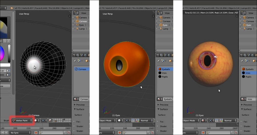
The Corneas object in Vertex Paint mode, the Eyes object with its three materials and the Rendered preview of the textured objects together
Start Blender and open the Gidiosaurus_skin_Cycle_02.blend file; save it as Gidiosaurus_shaders_Cycles.blend.
- Enable only the 6th and the 12th scene layer, in order to have visible only the Corneas, the Eyes and the Lamp objects (actually the Camera is also on the 6th scene layer, but it's hidden and at the moment we don't need it).
- Zoom the 3D view onto the Corneas and Eyes objects, and press Shift + Z to start the Rendered preview.
- In the Outliner, disable the Restrict view-port visibility button of the Eyes object to hide it.
- Select the Corneas object and go to the Material window.
So, let's start with the Corneas material, first:
- In the Material window, click on the New button in the Surface subpanel. Rename the material as
Corneas. - In the Material window, switch the Diffuse BSDF shader node with a Mix Shader node (label it as Mix Shader_1). In the first Shader slot, select a Diffuse BSDF shader node and in the second one select a Glossy BSDF shader (label it as Glossy BSDF1).
- Go to the Node Editor window and set the Roughness of the Glossy BSDF1 shader to 0.150, the Color to pure white and the Distribution to Sharp.
- Select the Mix Shader_1 node and press Shift + D to duplicate it. Label the duplicate as Mix Shader_2, then add a Subsurface Scattering node (Shift + A | Shader | Subsurface Scattering). Connect the output of the Mix Shader_1 node to the first Shader input socket of the Mix Shader_2 node and the output of the Subsurface Scattering shader node to the second Shader input socket.
- Change the Subsurface Scattering falloff from Cubic to Gaussian, set the Scale to 0.001 and the Radius to R 9.436, G 3.348, B 1.790.
- Add a Fresnel node (Shift + A | Input | Fresnel) and connect its output to the Fac input socket of the Mix Shader_2 node; set the IOR to 1.340:

The basic starting "Corneas" shader
- Add a new Mix Shader node (Shift + A | Shader | Mix Shader), label it as Mix Shader_3 and paste it between the Mix Shader_2 and the Material Output node.
- Add a new Mix Shader node (Shift + A | Shader | Mix Shader), label it as Mix Shader_4 and connect its output to the second Shader input socket of the Mix Shader_3 node.
- Add a Transparent BSDF shader (Shift + A | Shader | Transparent BSDF) and connect it to the first Shader input socket of the Mix Shader_4 node.
- Select and press Shift + D to duplicate the Glossy BSDF1 node; label the duplicate as Glossy BSDF2 and connect its output to the second Shader input socket of the Mix Shader_4 node:

The "Corneas" shader with the added transparency nodes
- Add a Layer Weight node (Shift + A | Input | Layer Weight) and a Math node (Shift + A | Converter | Math); set the Blend factor of the Layer Weight to 0.300 and connect its Facing output to the first Value input socket of the Math node, then set the second Value to 0.100 and check the Clamp item.
- Connect the Math (labeled as Add) output to the Fac input sockets of the Mix Shader_1 and Mix Shader_4 nodes.
- Add an Attribute node (Shift + A | Input | Attribute) and a ColorRamp node (Shift + A | Converter | ColorRamp). In the Name slot of the Attribute node, type Col, then connect its Color output to the Fac input socket of the ColorRamp node.
- In the ColorRamp node, set the Interpolation to B-Spline and move the white color stop to position 0.100. Connect its Color output to the Fac input socket of the Mix Shader_3 node.

The "Corneas" shader with the transparency area located by the Vertex Color layer
- Add two Image Textures nodes (Shift + A | Texture | Image Texture) and label them respectively as COL and BUMP.
- Add an Attribute node (Shift + A | Input | Attribute); in the Name slot type UVMap.001 and connect its Vector output to the Vector input sockets of the two image texture nodes.
- Add an RGB node (Shift + A | Input | RGB), a MixRGB node (Shift + A | Input | MixRGB) and a Hue Saturation Value node (Shift + A | Input | Hue/Saturation).
- Click on the Open button of the COL node to browse to the
texturesfolder and load the imageeyeball_col.jpg. - Connect the Color output of the COL node to the Color2 input socket of the MixRGB node and the output of the RGB node to the Color1 input socket; set the Blend Type to Burn and the Fac value to 0.800.
- Connect the Color output of the MixRGB node to the Color input socket of the Hue Saturation Value node, and the output of this latter node to the Color input sockets of the Diffuse BSDF and Subsurface Scattering nodes.
- Set the RGB node color to R 0.800, G 0.466, B 0.000; set the Saturation value of the Hue Saturation Value node to 0.900.
- Click on the Open button of the BUMP node to browse to the
texturesfolder and load the imageeyeball_bump.jpg; set Color Space to Non-Color Data. - Add a Bump node (Shift + A | Vector | Bump) and connect the Color output of the BUMP node to the Height input socket of the Bump node. Connect the Normal output of this latter node to the Normal input sockets of the Diffuse BSDF, Glossy BSDF1, and Subsurface Scattering nodes, and set the Strength to 0.050.
- If you wish, add frames and colors to the different components to make the shader more easily readable:

The textured "Corneas" material
Now let's quickly see the materials for the Eyes object:
- As you can see in the following screenshot, the
Eyeballsmaterial is essentially the same as we just made for the Corneas except for the transparent part; this material, by the way, is obsolete because it's hidden behind the Corneas' opaque surface, so can be safely omitted (but I left it in place in case you want to try the totally transparent Cornea):
The "Eyeballs" material and the completed rendered eye
- The
Irisesmaterial follows the same scheme; the only differences are in the fact that it uses different image textures (iris_col.jpgandiris_bump.jpg) and that a contrasted (by a ColorRamp node) version of the bump image is used as a factor for the mixing of an Emission shader; note that the color map is also connected to this Emission shader:
The "Irises" material network
- The Pupils are a simple, basic, black diffuse material.
To have a look at these materials, open the Gidiosaurus_shaders_Cycles.blend file and select the Corneas and Eyes objects in the Outliner.
These shaders are quite simple; the more complex one is the shader for the Corneas, essentially because it's made up of two materials, one with a slight bump effect and one totally smooth, mixed on the ground of the black and white Vertex Color layer that takes care also of the distribution of the transparent and opaque materials on the Corneas object itself.
If you are wondering why we didn't use the Eyeball material on the underlying Eyes sphere, leaving the Corneas object totally transparent, the reason is simple: in Cycles, to have a material transparent but also reflecting the environment, you need to use a Transparent shader mixed with a Glass or a Glossy shader node, that inevitably will make whatever material is behind appear darker; sometimes this can look right, in this case I preferred to use a different approach.
Getting ready
Start Blender and open the Gidiosaurus_skin_Cycle_02.blend file; save it as Gidiosaurus_shaders_Cycles.blend.
- Enable only the 6th and the 12th scene layer, in order to have visible only the Corneas, the Eyes and the Lamp objects (actually the Camera is also on the 6th scene layer, but it's hidden and at the moment we don't need it).
- Zoom the 3D view onto the Corneas and Eyes objects, and press Shift + Z to start the Rendered preview.
- In the Outliner, disable the Restrict view-port visibility button of the Eyes object to hide it.
- Select the Corneas object and go to the Material window.
So, let's start with the Corneas material, first:
- In the Material window, click on the New button in the Surface subpanel. Rename the material as
Corneas. - In the Material window, switch the Diffuse BSDF shader node with a Mix Shader node (label it as Mix Shader_1). In the first Shader slot, select a Diffuse BSDF shader node and in the second one select a Glossy BSDF shader (label it as Glossy BSDF1).
- Go to the Node Editor window and set the Roughness of the Glossy BSDF1 shader to 0.150, the Color to pure white and the Distribution to Sharp.
- Select the Mix Shader_1 node and press Shift + D to duplicate it. Label the duplicate as Mix Shader_2, then add a Subsurface Scattering node (Shift + A | Shader | Subsurface Scattering). Connect the output of the Mix Shader_1 node to the first Shader input socket of the Mix Shader_2 node and the output of the Subsurface Scattering shader node to the second Shader input socket.
- Change the Subsurface Scattering falloff from Cubic to Gaussian, set the Scale to 0.001 and the Radius to R 9.436, G 3.348, B 1.790.
- Add a Fresnel node (Shift + A | Input | Fresnel) and connect its output to the Fac input socket of the Mix Shader_2 node; set the IOR to 1.340:
The basic starting "Corneas" shader
- Add a new Mix Shader node (Shift + A | Shader | Mix Shader), label it as Mix Shader_3 and paste it between the Mix Shader_2 and the Material Output node.
- Add a new Mix Shader node (Shift + A | Shader | Mix Shader), label it as Mix Shader_4 and connect its output to the second Shader input socket of the Mix Shader_3 node.
- Add a Transparent BSDF shader (Shift + A | Shader | Transparent BSDF) and connect it to the first Shader input socket of the Mix Shader_4 node.
- Select and press Shift + D to duplicate the Glossy BSDF1 node; label the duplicate as Glossy BSDF2 and connect its output to the second Shader input socket of the Mix Shader_4 node:
The "Corneas" shader with the added transparency nodes
- Add a Layer Weight node (Shift + A | Input | Layer Weight) and a Math node (Shift + A | Converter | Math); set the Blend factor of the Layer Weight to 0.300 and connect its Facing output to the first Value input socket of the Math node, then set the second Value to 0.100 and check the Clamp item.
- Connect the Math (labeled as Add) output to the Fac input sockets of the Mix Shader_1 and Mix Shader_4 nodes.
- Add an Attribute node (Shift + A | Input | Attribute) and a ColorRamp node (Shift + A | Converter | ColorRamp). In the Name slot of the Attribute node, type Col, then connect its Color output to the Fac input socket of the ColorRamp node.
- In the ColorRamp node, set the Interpolation to B-Spline and move the white color stop to position 0.100. Connect its Color output to the Fac input socket of the Mix Shader_3 node.
The "Corneas" shader with the transparency area located by the Vertex Color layer
- Add two Image Textures nodes (Shift + A | Texture | Image Texture) and label them respectively as COL and BUMP.
- Add an Attribute node (Shift + A | Input | Attribute); in the Name slot type UVMap.001 and connect its Vector output to the Vector input sockets of the two image texture nodes.
- Add an RGB node (Shift + A | Input | RGB), a MixRGB node (Shift + A | Input | MixRGB) and a Hue Saturation Value node (Shift + A | Input | Hue/Saturation).
- Click on the Open button of the COL node to browse to the
texturesfolder and load the imageeyeball_col.jpg. - Connect the Color output of the COL node to the Color2 input socket of the MixRGB node and the output of the RGB node to the Color1 input socket; set the Blend Type to Burn and the Fac value to 0.800.
- Connect the Color output of the MixRGB node to the Color input socket of the Hue Saturation Value node, and the output of this latter node to the Color input sockets of the Diffuse BSDF and Subsurface Scattering nodes.
- Set the RGB node color to R 0.800, G 0.466, B 0.000; set the Saturation value of the Hue Saturation Value node to 0.900.
- Click on the Open button of the BUMP node to browse to the
texturesfolder and load the imageeyeball_bump.jpg; set Color Space to Non-Color Data. - Add a Bump node (Shift + A | Vector | Bump) and connect the Color output of the BUMP node to the Height input socket of the Bump node. Connect the Normal output of this latter node to the Normal input sockets of the Diffuse BSDF, Glossy BSDF1, and Subsurface Scattering nodes, and set the Strength to 0.050.
- If you wish, add frames and colors to the different components to make the shader more easily readable:
The textured "Corneas" material
Now let's quickly see the materials for the Eyes object:
- As you can see in the following screenshot, the
Eyeballsmaterial is essentially the same as we just made for the Corneas except for the transparent part; this material, by the way, is obsolete because it's hidden behind the Corneas' opaque surface, so can be safely omitted (but I left it in place in case you want to try the totally transparent Cornea):The "Eyeballs" material and the completed rendered eye
- The
Irisesmaterial follows the same scheme; the only differences are in the fact that it uses different image textures (iris_col.jpgandiris_bump.jpg) and that a contrasted (by a ColorRamp node) version of the bump image is used as a factor for the mixing of an Emission shader; note that the color map is also connected to this Emission shader:The "Irises" material network
- The Pupils are a simple, basic, black diffuse material.
To have a look at these materials, open the Gidiosaurus_shaders_Cycles.blend file and select the Corneas and Eyes objects in the Outliner.
These shaders are quite simple; the more complex one is the shader for the Corneas, essentially because it's made up of two materials, one with a slight bump effect and one totally smooth, mixed on the ground of the black and white Vertex Color layer that takes care also of the distribution of the transparent and opaque materials on the Corneas object itself.
If you are wondering why we didn't use the Eyeball material on the underlying Eyes sphere, leaving the Corneas object totally transparent, the reason is simple: in Cycles, to have a material transparent but also reflecting the environment, you need to use a Transparent shader mixed with a Glass or a Glossy shader node, that inevitably will make whatever material is behind appear darker; sometimes this can look right, in this case I preferred to use a different approach.
How to do it…
So, let's start with the Corneas material, first:
- In the Material window, click on the New button in the Surface subpanel. Rename the material as
Corneas. - In the Material window, switch the Diffuse BSDF shader node with a Mix Shader node (label it as Mix Shader_1). In the first Shader slot, select a Diffuse BSDF shader node and in the second one select a Glossy BSDF shader (label it as Glossy BSDF1).
- Go to the Node Editor window and set the Roughness of the Glossy BSDF1 shader to 0.150, the Color to pure white and the Distribution to Sharp.
- Select the Mix Shader_1 node and press Shift + D to duplicate it. Label the duplicate as Mix Shader_2, then add a Subsurface Scattering node (Shift + A | Shader | Subsurface Scattering). Connect the output of the Mix Shader_1 node to the first Shader input socket of the Mix Shader_2 node and the output of the Subsurface Scattering shader node to the second Shader input socket.
- Change the Subsurface Scattering falloff from Cubic to Gaussian, set the Scale to 0.001 and the Radius to R 9.436, G 3.348, B 1.790.
- Add a Fresnel node (Shift + A | Input | Fresnel) and connect its output to the Fac input socket of the Mix Shader_2 node; set the IOR to 1.340:
The basic starting "Corneas" shader
- Add a new Mix Shader node (Shift + A | Shader | Mix Shader), label it as Mix Shader_3 and paste it between the Mix Shader_2 and the Material Output node.
- Add a new Mix Shader node (Shift + A | Shader | Mix Shader), label it as Mix Shader_4 and connect its output to the second Shader input socket of the Mix Shader_3 node.
- Add a Transparent BSDF shader (Shift + A | Shader | Transparent BSDF) and connect it to the first Shader input socket of the Mix Shader_4 node.
- Select and press Shift + D to duplicate the Glossy BSDF1 node; label the duplicate as Glossy BSDF2 and connect its output to the second Shader input socket of the Mix Shader_4 node:
The "Corneas" shader with the added transparency nodes
- Add a Layer Weight node (Shift + A | Input | Layer Weight) and a Math node (Shift + A | Converter | Math); set the Blend factor of the Layer Weight to 0.300 and connect its Facing output to the first Value input socket of the Math node, then set the second Value to 0.100 and check the Clamp item.
- Connect the Math (labeled as Add) output to the Fac input sockets of the Mix Shader_1 and Mix Shader_4 nodes.
- Add an Attribute node (Shift + A | Input | Attribute) and a ColorRamp node (Shift + A | Converter | ColorRamp). In the Name slot of the Attribute node, type Col, then connect its Color output to the Fac input socket of the ColorRamp node.
- In the ColorRamp node, set the Interpolation to B-Spline and move the white color stop to position 0.100. Connect its Color output to the Fac input socket of the Mix Shader_3 node.
The "Corneas" shader with the transparency area located by the Vertex Color layer
- Add two Image Textures nodes (Shift + A | Texture | Image Texture) and label them respectively as COL and BUMP.
- Add an Attribute node (Shift + A | Input | Attribute); in the Name slot type UVMap.001 and connect its Vector output to the Vector input sockets of the two image texture nodes.
- Add an RGB node (Shift + A | Input | RGB), a MixRGB node (Shift + A | Input | MixRGB) and a Hue Saturation Value node (Shift + A | Input | Hue/Saturation).
- Click on the Open button of the COL node to browse to the
texturesfolder and load the imageeyeball_col.jpg. - Connect the Color output of the COL node to the Color2 input socket of the MixRGB node and the output of the RGB node to the Color1 input socket; set the Blend Type to Burn and the Fac value to 0.800.
- Connect the Color output of the MixRGB node to the Color input socket of the Hue Saturation Value node, and the output of this latter node to the Color input sockets of the Diffuse BSDF and Subsurface Scattering nodes.
- Set the RGB node color to R 0.800, G 0.466, B 0.000; set the Saturation value of the Hue Saturation Value node to 0.900.
- Click on the Open button of the BUMP node to browse to the
texturesfolder and load the imageeyeball_bump.jpg; set Color Space to Non-Color Data. - Add a Bump node (Shift + A | Vector | Bump) and connect the Color output of the BUMP node to the Height input socket of the Bump node. Connect the Normal output of this latter node to the Normal input sockets of the Diffuse BSDF, Glossy BSDF1, and Subsurface Scattering nodes, and set the Strength to 0.050.
- If you wish, add frames and colors to the different components to make the shader more easily readable:
The textured "Corneas" material
Now let's quickly see the materials for the Eyes object:
- As you can see in the following screenshot, the
Eyeballsmaterial is essentially the same as we just made for the Corneas except for the transparent part; this material, by the way, is obsolete because it's hidden behind the Corneas' opaque surface, so can be safely omitted (but I left it in place in case you want to try the totally transparent Cornea):The "Eyeballs" material and the completed rendered eye
- The
Irisesmaterial follows the same scheme; the only differences are in the fact that it uses different image textures (iris_col.jpgandiris_bump.jpg) and that a contrasted (by a ColorRamp node) version of the bump image is used as a factor for the mixing of an Emission shader; note that the color map is also connected to this Emission shader:The "Irises" material network
- The Pupils are a simple, basic, black diffuse material.
To have a look at these materials, open the Gidiosaurus_shaders_Cycles.blend file and select the Corneas and Eyes objects in the Outliner.
These shaders are quite simple; the more complex one is the shader for the Corneas, essentially because it's made up of two materials, one with a slight bump effect and one totally smooth, mixed on the ground of the black and white Vertex Color layer that takes care also of the distribution of the transparent and opaque materials on the Corneas object itself.
If you are wondering why we didn't use the Eyeball material on the underlying Eyes sphere, leaving the Corneas object totally transparent, the reason is simple: in Cycles, to have a material transparent but also reflecting the environment, you need to use a Transparent shader mixed with a Glass or a Glossy shader node, that inevitably will make whatever material is behind appear darker; sometimes this can look right, in this case I preferred to use a different approach.
How it works…
These shaders are quite simple; the more complex one is the shader for the Corneas, essentially because it's made up of two materials, one with a slight bump effect and one totally smooth, mixed on the ground of the black and white Vertex Color layer that takes care also of the distribution of the transparent and opaque materials on the Corneas object itself.
If you are wondering why we didn't use the Eyeball material on the underlying Eyes sphere, leaving the Corneas object totally transparent, the reason is simple: in Cycles, to have a material transparent but also reflecting the environment, you need to use a Transparent shader mixed with a Glass or a Glossy shader node, that inevitably will make whatever material is behind appear darker; sometimes this can look right, in this case I preferred to use a different approach.
The last thing to do, for this chapter, is to create the shaders for the Armor object, made up of metallic plates and leather tiers.
Continuing from the previously saved blend file:
- Enable the 6th and the 13th scene layer and select the Armor object in the Outliner.
- Put the mouse pointer in the 3D viewport and press the 0 key on the numpad to go into Camera view; fit the window into the field of view.
- Go to the Material window and press the + icon button to the right side to add four empty material slots to the armor. Select the first material slot and click on the New button in the Surface subpanel, and rename the material
Armor_U0V0. - Select the second material slot, click on the New button and rename the material as
Armor_U1V0; repeat for the third slot and rename the material asLeatherand repeat also for the fourth slot and rename the materialArmor_rivets. - Switch the Node Editor window temporarily with a UV/Image Editor window, then press Tab to go into Edit Mode; go to the UV Maps subpanel under the Object Data window to be sure you have the UVMap coordinates layer (the first one) as the active one, then enable the Keep UV and edit mode mesh selection in sync button on the UV/Image Editor toolbar.
- In the Node Editor window, box-select the UV islands of the U1V0 tile, then in the Material window, select the
Armor_U1V0material and click on the Assign button. - Still in Edit Mode, select all the tiers vertices and then select the
Leathermaterial, click on the Assign button; repeat the operation by selecting all the rivets and assigning them to theArmor_rivetsmaterial. - Disable the Keep UV and edit mode mesh selection in sync button on the UV/Image Editor toolbar, go out of Edit Mode and switch the UV/Image Editor window back to the Node Editor window.
- Put the mouse pointer inside the 3D viewport and press Shift + Z to start the Rendered preview.
We are first going to create the shader for the metal plates:
- In the Material window, select the
Armor_U0V0material slot. - Go to the Node Editor window and switch the Diffuse BSDF shader node with a Mix Shader node; in the first Shader slot, select a Diffuse BSDF shader node and in the second one, select an Anisotropic BSDF shader.
- Go to the Node Editor window and set the Roughness of the Diffuse BSDF shader to 0.300 and the Anisotropy of the Anisotropic BSDF shader to 0.300.
- Add a Fresnel node (Shift + A | Input | Fresnel) and connect its output to the Fac input socket of the Mix Shader node; set the IOR to 100.000.
- Add a Tangent node (Shift + A | Input | Tangent) and connect its output to the Tangent input socket of the Anisotropic BSDF shader node; set the Tangent to Z.

Starting to build the metal shader for the armor
- Add a Frame (Shift + A | Layout | Frame) and parent the nodes, except the Material Output, to it, then label it as SHADERS.
- Add three Image Textures nodes (Shift + A | Texture | Image Texture) and a Voronoi Texture node (Shift + A | Texture | Voronoi Texture), then add two Attribute nodes (Shift + A | Input | Attribute) and a Texture Coordinate node (Shift + A | Input | Texture Coordinate).
- Label the Attribute nodes as Attribute_UV1 and Attribute_UV2. Label the Image Texture nodes as COL_iron, NORMALS_iron, and VCOL_iron.
- Connect the Vector output of the Attribute_UV1 node to the Vector input socket of the COL_iron node. Connect the Vector output of the Attribute_UV2 to the Vector input sockets of both the VCOL_iron and NORMALS_iron nodes. Connect the Object output of the Texture Coordinate node to the Vector input socket of the Voronoi Texture node.
- Click on the Open button of the VCOL_iron node, browse to the
texturesfolder and load the imagevcol2.png. Set the Color Space to Non-Color Data. Connect its Color output to the Roughness input socket of the Anisotropic BSDF shader node. - Click on the Open button of the COL_iron node, browse to the
texturesfolder and load the imageiron_U0V0.png. Connect its Color output to the Color input sockets of the Diffuse BSDF and Anisotropic BSDF shader nodes. - Click on the Open button of the NORMALS_iron node, browse to the
texturesfolder and load the imagenorm2.png. Set the Color Space to Non-Color Data. - Set the Scale of the Voronoi Texture to 15.000:

Adding the textures to the "Armor_U0V0" material
- Add a ColorRamp node (Shift + A | Converter | ColorRamp) and a Math node (Shift + A | Converter | Math). Paste the ColorRamp node right after the VCOL node, and the Math node right after the ColorRamp.
- Label the ColorRamp as ColorRamp_Vcol and set the Interpolation to B-Spline, then move the black color stop to position 0.245 and the white color stop to position 0.755.
- Label the Math node as Spec_soften and set the second Value to 0.100.
- Add a MixRGB node (Shift + A | Color | MixRGB) and label it as Difference_Col_iron; set the Blend Type to Difference and the Fac value to 0.300.
- Connect the Color output of the COL node to the Color1 input socket and the Color output of the ColorRamp_Vcol node to the Color2 input socket. Connect the Color output of the Difference_Col_iron node to the Color input sockets of the Diffuse BSDF and the Anisotropic BSDF shader nodes, replacing the old connections.
- Add a Normal Map node (Shift + A | Vector | Normal Map), a Bump node (Shift + A | Vector | Bump), and a Vector Math node (Shift + A | Converter | Vector Math).
- Connect the Color output of the NORMALS_iron node to the Color input socket of the Normal Map node; click on the empty slot (UV Map for tangent space maps) on this latter node to select the UVMap_norm item.
- Connect the Normal output of the Normal Map node to the first Vector input socket of the Vector Math node; label this latter as Average_Normals and set the Operation to Average, then connect its Vector output to the Normal input sockets of the Diffuse BSDF and Anisotropic BSDF shader nodes.
- Add a MixRGB node (Shift + A | Color | MixRGB), label it as Add_Bump, set the Blend Type to Add and the Fac value to 1.000. Connect the Color output of the COL node to the Color1 input socket of the Add_Bump node also, and the Color output of the Voronoi Texture node to the Color2 input socket.
- Connect the Color output of the Add_Bump node to the Height input socket of the Bump node, and the Normal output of this latter node to the second Vector input socket of the Average_Normals node. Set the Strength of the Bump node to 1.000.
- Add two Math nodes (Shift + A | Converter | Math), label them respectively as Bump_strength1 and Bump_strength2; set the Operation to Multiply for both, then paste the Bump_strength1 node between the COL_iron and the Add_Bump nodes and set the second Value to 0.020. Paste the Bump_strength2 node between the Voronoi_Texture and the Add_Bump nodes, and set the second Value to 0.010.
- Add frames to highlight the different components:

The completed "Armor_U0V0" material
The first Armor shader is ready! Now it's very easy to obtain the others:
- Press A twice to select all the nodes, then press Ctrl + C to copy them.
- In the Material window, select the
Armor_U1V0material slot and in the Node Editor window, delete the default Diffuse and Material Output nodes; then press Ctrl + V to paste the nodes copied from the other material. - Zoom to the COL node and click on the numbered button to the right side of the texture name slot to make it single user, then click on the folder icon button to browse to the
texturefolder and load the imageiron_U1V0.png. - Reselect the
Armor_U0V0material slot and repeat the step 26 and 27, this time pasting the nodes inside theArmor_rivetsmaterial slot:
The "Armor_rivets" material and the rendered completed armor
- Save the file.
The construction of the metallic armor plates material follows basically the same scheme we used for the other materials:
- First the shaders were produced, where the metallic look is mainly due to the Anisotropic BSDF shader mixed with the diffuse component with a quite high IOR value (metals can often have values from 20.000 to 200.000; we used a midway value of 100.000).
- The shininess of the metallic surface has been modulated through the output of the
vcol2.pngimage, a Dirty Vertex Color layer we had previously baked to an image. - The color of the Armor surface has been modulated as well through a Difference node with the same
vcol2.pngimage. - The bump pattern works by first adding the Voronoi and the color map output and then averaging the result with the normal map output.
The last material created for our character is a very simple leather material made mainly from the output of a Voronoi Texture node, contrasted, inverted, and used as bump pattern:
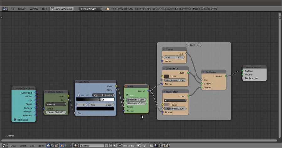
The simple "Leather" material
This completes the creation of the Gidiosaurus shaders in Cycles:
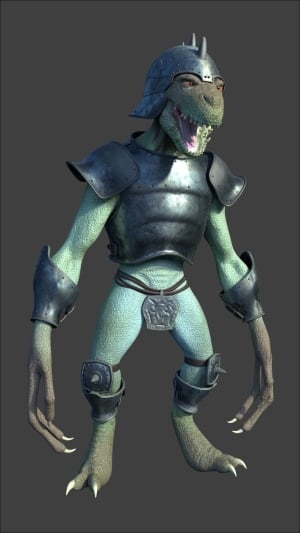
The completed Gidiosaurus character in Cycles
Of course, reflecting materials, for example, the metallic armor surface or the corneas (but to some extent also the reptile skin), need something to reflect to show them at their best; we'll see this in the last chapter of this cookbook.
In the next chapter, which is the penultimate chapter, we'll see the creation of the same materials in Blender Internal.
Getting ready
Continuing from the previously saved blend file:
- Enable the 6th and the 13th scene layer and select the Armor object in the Outliner.
- Put the mouse pointer in the 3D viewport and press the 0 key on the numpad to go into Camera view; fit the window into the field of view.
- Go to the Material window and press the + icon button to the right side to add four empty material slots to the armor. Select the first material slot and click on the New button in the Surface subpanel, and rename the material
Armor_U0V0. - Select the second material slot, click on the New button and rename the material as
Armor_U1V0; repeat for the third slot and rename the material asLeatherand repeat also for the fourth slot and rename the materialArmor_rivets. - Switch the Node Editor window temporarily with a UV/Image Editor window, then press Tab to go into Edit Mode; go to the UV Maps subpanel under the Object Data window to be sure you have the UVMap coordinates layer (the first one) as the active one, then enable the Keep UV and edit mode mesh selection in sync button on the UV/Image Editor toolbar.
- In the Node Editor window, box-select the UV islands of the U1V0 tile, then in the Material window, select the
Armor_U1V0material and click on the Assign button. - Still in Edit Mode, select all the tiers vertices and then select the
Leathermaterial, click on the Assign button; repeat the operation by selecting all the rivets and assigning them to theArmor_rivetsmaterial. - Disable the Keep UV and edit mode mesh selection in sync button on the UV/Image Editor toolbar, go out of Edit Mode and switch the UV/Image Editor window back to the Node Editor window.
- Put the mouse pointer inside the 3D viewport and press Shift + Z to start the Rendered preview.
We are first going to create the shader for the metal plates:
- In the Material window, select the
Armor_U0V0material slot. - Go to the Node Editor window and switch the Diffuse BSDF shader node with a Mix Shader node; in the first Shader slot, select a Diffuse BSDF shader node and in the second one, select an Anisotropic BSDF shader.
- Go to the Node Editor window and set the Roughness of the Diffuse BSDF shader to 0.300 and the Anisotropy of the Anisotropic BSDF shader to 0.300.
- Add a Fresnel node (Shift + A | Input | Fresnel) and connect its output to the Fac input socket of the Mix Shader node; set the IOR to 100.000.
- Add a Tangent node (Shift + A | Input | Tangent) and connect its output to the Tangent input socket of the Anisotropic BSDF shader node; set the Tangent to Z.
Starting to build the metal shader for the armor
- Add a Frame (Shift + A | Layout | Frame) and parent the nodes, except the Material Output, to it, then label it as SHADERS.
- Add three Image Textures nodes (Shift + A | Texture | Image Texture) and a Voronoi Texture node (Shift + A | Texture | Voronoi Texture), then add two Attribute nodes (Shift + A | Input | Attribute) and a Texture Coordinate node (Shift + A | Input | Texture Coordinate).
- Label the Attribute nodes as Attribute_UV1 and Attribute_UV2. Label the Image Texture nodes as COL_iron, NORMALS_iron, and VCOL_iron.
- Connect the Vector output of the Attribute_UV1 node to the Vector input socket of the COL_iron node. Connect the Vector output of the Attribute_UV2 to the Vector input sockets of both the VCOL_iron and NORMALS_iron nodes. Connect the Object output of the Texture Coordinate node to the Vector input socket of the Voronoi Texture node.
- Click on the Open button of the VCOL_iron node, browse to the
texturesfolder and load the imagevcol2.png. Set the Color Space to Non-Color Data. Connect its Color output to the Roughness input socket of the Anisotropic BSDF shader node. - Click on the Open button of the COL_iron node, browse to the
texturesfolder and load the imageiron_U0V0.png. Connect its Color output to the Color input sockets of the Diffuse BSDF and Anisotropic BSDF shader nodes. - Click on the Open button of the NORMALS_iron node, browse to the
texturesfolder and load the imagenorm2.png. Set the Color Space to Non-Color Data. - Set the Scale of the Voronoi Texture to 15.000:
Adding the textures to the "Armor_U0V0" material
- Add a ColorRamp node (Shift + A | Converter | ColorRamp) and a Math node (Shift + A | Converter | Math). Paste the ColorRamp node right after the VCOL node, and the Math node right after the ColorRamp.
- Label the ColorRamp as ColorRamp_Vcol and set the Interpolation to B-Spline, then move the black color stop to position 0.245 and the white color stop to position 0.755.
- Label the Math node as Spec_soften and set the second Value to 0.100.
- Add a MixRGB node (Shift + A | Color | MixRGB) and label it as Difference_Col_iron; set the Blend Type to Difference and the Fac value to 0.300.
- Connect the Color output of the COL node to the Color1 input socket and the Color output of the ColorRamp_Vcol node to the Color2 input socket. Connect the Color output of the Difference_Col_iron node to the Color input sockets of the Diffuse BSDF and the Anisotropic BSDF shader nodes, replacing the old connections.
- Add a Normal Map node (Shift + A | Vector | Normal Map), a Bump node (Shift + A | Vector | Bump), and a Vector Math node (Shift + A | Converter | Vector Math).
- Connect the Color output of the NORMALS_iron node to the Color input socket of the Normal Map node; click on the empty slot (UV Map for tangent space maps) on this latter node to select the UVMap_norm item.
- Connect the Normal output of the Normal Map node to the first Vector input socket of the Vector Math node; label this latter as Average_Normals and set the Operation to Average, then connect its Vector output to the Normal input sockets of the Diffuse BSDF and Anisotropic BSDF shader nodes.
- Add a MixRGB node (Shift + A | Color | MixRGB), label it as Add_Bump, set the Blend Type to Add and the Fac value to 1.000. Connect the Color output of the COL node to the Color1 input socket of the Add_Bump node also, and the Color output of the Voronoi Texture node to the Color2 input socket.
- Connect the Color output of the Add_Bump node to the Height input socket of the Bump node, and the Normal output of this latter node to the second Vector input socket of the Average_Normals node. Set the Strength of the Bump node to 1.000.
- Add two Math nodes (Shift + A | Converter | Math), label them respectively as Bump_strength1 and Bump_strength2; set the Operation to Multiply for both, then paste the Bump_strength1 node between the COL_iron and the Add_Bump nodes and set the second Value to 0.020. Paste the Bump_strength2 node between the Voronoi_Texture and the Add_Bump nodes, and set the second Value to 0.010.
- Add frames to highlight the different components:
The completed "Armor_U0V0" material
The first Armor shader is ready! Now it's very easy to obtain the others:
- Press A twice to select all the nodes, then press Ctrl + C to copy them.
- In the Material window, select the
Armor_U1V0material slot and in the Node Editor window, delete the default Diffuse and Material Output nodes; then press Ctrl + V to paste the nodes copied from the other material. - Zoom to the COL node and click on the numbered button to the right side of the texture name slot to make it single user, then click on the folder icon button to browse to the
texturefolder and load the imageiron_U1V0.png. - Reselect the
Armor_U0V0material slot and repeat the step 26 and 27, this time pasting the nodes inside theArmor_rivetsmaterial slot:The "Armor_rivets" material and the rendered completed armor
- Save the file.
The construction of the metallic armor plates material follows basically the same scheme we used for the other materials:
- First the shaders were produced, where the metallic look is mainly due to the Anisotropic BSDF shader mixed with the diffuse component with a quite high IOR value (metals can often have values from 20.000 to 200.000; we used a midway value of 100.000).
- The shininess of the metallic surface has been modulated through the output of the
vcol2.pngimage, a Dirty Vertex Color layer we had previously baked to an image. - The color of the Armor surface has been modulated as well through a Difference node with the same
vcol2.pngimage. - The bump pattern works by first adding the Voronoi and the color map output and then averaging the result with the normal map output.
The last material created for our character is a very simple leather material made mainly from the output of a Voronoi Texture node, contrasted, inverted, and used as bump pattern:
The simple "Leather" material
This completes the creation of the Gidiosaurus shaders in Cycles:
The completed Gidiosaurus character in Cycles
Of course, reflecting materials, for example, the metallic armor surface or the corneas (but to some extent also the reptile skin), need something to reflect to show them at their best; we'll see this in the last chapter of this cookbook.
In the next chapter, which is the penultimate chapter, we'll see the creation of the same materials in Blender Internal.
How to do it…
We are first going to create the shader for the metal plates:
- In the Material window, select the
Armor_U0V0material slot. - Go to the Node Editor window and switch the Diffuse BSDF shader node with a Mix Shader node; in the first Shader slot, select a Diffuse BSDF shader node and in the second one, select an Anisotropic BSDF shader.
- Go to the Node Editor window and set the Roughness of the Diffuse BSDF shader to 0.300 and the Anisotropy of the Anisotropic BSDF shader to 0.300.
- Add a Fresnel node (Shift + A | Input | Fresnel) and connect its output to the Fac input socket of the Mix Shader node; set the IOR to 100.000.
- Add a Tangent node (Shift + A | Input | Tangent) and connect its output to the Tangent input socket of the Anisotropic BSDF shader node; set the Tangent to Z.
Starting to build the metal shader for the armor
- Add a Frame (Shift + A | Layout | Frame) and parent the nodes, except the Material Output, to it, then label it as SHADERS.
- Add three Image Textures nodes (Shift + A | Texture | Image Texture) and a Voronoi Texture node (Shift + A | Texture | Voronoi Texture), then add two Attribute nodes (Shift + A | Input | Attribute) and a Texture Coordinate node (Shift + A | Input | Texture Coordinate).
- Label the Attribute nodes as Attribute_UV1 and Attribute_UV2. Label the Image Texture nodes as COL_iron, NORMALS_iron, and VCOL_iron.
- Connect the Vector output of the Attribute_UV1 node to the Vector input socket of the COL_iron node. Connect the Vector output of the Attribute_UV2 to the Vector input sockets of both the VCOL_iron and NORMALS_iron nodes. Connect the Object output of the Texture Coordinate node to the Vector input socket of the Voronoi Texture node.
- Click on the Open button of the VCOL_iron node, browse to the
texturesfolder and load the imagevcol2.png. Set the Color Space to Non-Color Data. Connect its Color output to the Roughness input socket of the Anisotropic BSDF shader node. - Click on the Open button of the COL_iron node, browse to the
texturesfolder and load the imageiron_U0V0.png. Connect its Color output to the Color input sockets of the Diffuse BSDF and Anisotropic BSDF shader nodes. - Click on the Open button of the NORMALS_iron node, browse to the
texturesfolder and load the imagenorm2.png. Set the Color Space to Non-Color Data. - Set the Scale of the Voronoi Texture to 15.000:
Adding the textures to the "Armor_U0V0" material
- Add a ColorRamp node (Shift + A | Converter | ColorRamp) and a Math node (Shift + A | Converter | Math). Paste the ColorRamp node right after the VCOL node, and the Math node right after the ColorRamp.
- Label the ColorRamp as ColorRamp_Vcol and set the Interpolation to B-Spline, then move the black color stop to position 0.245 and the white color stop to position 0.755.
- Label the Math node as Spec_soften and set the second Value to 0.100.
- Add a MixRGB node (Shift + A | Color | MixRGB) and label it as Difference_Col_iron; set the Blend Type to Difference and the Fac value to 0.300.
- Connect the Color output of the COL node to the Color1 input socket and the Color output of the ColorRamp_Vcol node to the Color2 input socket. Connect the Color output of the Difference_Col_iron node to the Color input sockets of the Diffuse BSDF and the Anisotropic BSDF shader nodes, replacing the old connections.
- Add a Normal Map node (Shift + A | Vector | Normal Map), a Bump node (Shift + A | Vector | Bump), and a Vector Math node (Shift + A | Converter | Vector Math).
- Connect the Color output of the NORMALS_iron node to the Color input socket of the Normal Map node; click on the empty slot (UV Map for tangent space maps) on this latter node to select the UVMap_norm item.
- Connect the Normal output of the Normal Map node to the first Vector input socket of the Vector Math node; label this latter as Average_Normals and set the Operation to Average, then connect its Vector output to the Normal input sockets of the Diffuse BSDF and Anisotropic BSDF shader nodes.
- Add a MixRGB node (Shift + A | Color | MixRGB), label it as Add_Bump, set the Blend Type to Add and the Fac value to 1.000. Connect the Color output of the COL node to the Color1 input socket of the Add_Bump node also, and the Color output of the Voronoi Texture node to the Color2 input socket.
- Connect the Color output of the Add_Bump node to the Height input socket of the Bump node, and the Normal output of this latter node to the second Vector input socket of the Average_Normals node. Set the Strength of the Bump node to 1.000.
- Add two Math nodes (Shift + A | Converter | Math), label them respectively as Bump_strength1 and Bump_strength2; set the Operation to Multiply for both, then paste the Bump_strength1 node between the COL_iron and the Add_Bump nodes and set the second Value to 0.020. Paste the Bump_strength2 node between the Voronoi_Texture and the Add_Bump nodes, and set the second Value to 0.010.
- Add frames to highlight the different components:
The completed "Armor_U0V0" material
The first Armor shader is ready! Now it's very easy to obtain the others:
- Press A twice to select all the nodes, then press Ctrl + C to copy them.
- In the Material window, select the
Armor_U1V0material slot and in the Node Editor window, delete the default Diffuse and Material Output nodes; then press Ctrl + V to paste the nodes copied from the other material. - Zoom to the COL node and click on the numbered button to the right side of the texture name slot to make it single user, then click on the folder icon button to browse to the
texturefolder and load the imageiron_U1V0.png. - Reselect the
Armor_U0V0material slot and repeat the step 26 and 27, this time pasting the nodes inside theArmor_rivetsmaterial slot:The "Armor_rivets" material and the rendered completed armor
- Save the file.
The construction of the metallic armor plates material follows basically the same scheme we used for the other materials:
- First the shaders were produced, where the metallic look is mainly due to the Anisotropic BSDF shader mixed with the diffuse component with a quite high IOR value (metals can often have values from 20.000 to 200.000; we used a midway value of 100.000).
- The shininess of the metallic surface has been modulated through the output of the
vcol2.pngimage, a Dirty Vertex Color layer we had previously baked to an image. - The color of the Armor surface has been modulated as well through a Difference node with the same
vcol2.pngimage. - The bump pattern works by first adding the Voronoi and the color map output and then averaging the result with the normal map output.
The last material created for our character is a very simple leather material made mainly from the output of a Voronoi Texture node, contrasted, inverted, and used as bump pattern:
The simple "Leather" material
This completes the creation of the Gidiosaurus shaders in Cycles:
The completed Gidiosaurus character in Cycles
Of course, reflecting materials, for example, the metallic armor surface or the corneas (but to some extent also the reptile skin), need something to reflect to show them at their best; we'll see this in the last chapter of this cookbook.
In the next chapter, which is the penultimate chapter, we'll see the creation of the same materials in Blender Internal.
How it works…
The construction of the metallic armor plates material follows basically the same scheme we used for the other materials:
- First the shaders were produced, where the metallic look is mainly due to the Anisotropic BSDF shader mixed with the diffuse component with a quite high IOR value (metals can often have values from 20.000 to 200.000; we used a midway value of 100.000).
- The shininess of the metallic surface has been modulated through the output of the
vcol2.pngimage, a Dirty Vertex Color layer we had previously baked to an image. - The color of the Armor surface has been modulated as well through a Difference node with the same
vcol2.pngimage. - The bump pattern works by first adding the Voronoi and the color map output and then averaging the result with the normal map output.
The last material created for our character is a very simple leather material made mainly from the output of a Voronoi Texture node, contrasted, inverted, and used as bump pattern:
The simple "Leather" material
This completes the creation of the Gidiosaurus shaders in Cycles:
The completed Gidiosaurus character in Cycles
Of course, reflecting materials, for example, the metallic armor surface or the corneas (but to some extent also the reptile skin), need something to reflect to show them at their best; we'll see this in the last chapter of this cookbook.
In the next chapter, which is the penultimate chapter, we'll see the creation of the same materials in Blender Internal.
There's more…
The last material created for our character is a very simple leather material made mainly from the output of a Voronoi Texture node, contrasted, inverted, and used as bump pattern:
The simple "Leather" material
This completes the creation of the Gidiosaurus shaders in Cycles:
The completed Gidiosaurus character in Cycles
Of course, reflecting materials, for example, the metallic armor surface or the corneas (but to some extent also the reptile skin), need something to reflect to show them at their best; we'll see this in the last chapter of this cookbook.
In the next chapter, which is the penultimate chapter, we'll see the creation of the same materials in Blender Internal.
In this chapter, we will cover the following recipes:
- Building the reptile skin shaders in Blender Internal
- Building the eyes' shaders in Blender Internal
- Building the armor shaders in Blender Internal
In this chapter we'll see how to set up the materials for the Gidiosaurus and the Armor in the Blender Render engine; in fact, although not exactly of the same quality as in Cycles, it is also possible to obtain quite similar shader results in Blender Internal:
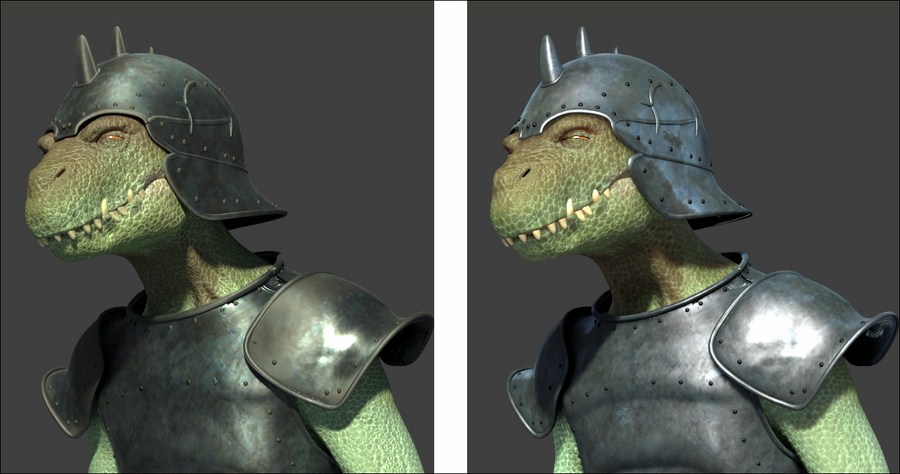
Comparison of the Gidiosaurus character rendered in Cycles (left) and Blender Internal (right)
If you are wondering why we should re-do in the Blender Render engine, which is quite old and no longer developed and/or supported, the same thing we have already done in Cycles, there are several possible reasons: for example, no doubt Cycles is superior in quality but, compared with the scanline BI, its rendering is (and, being a path-tracer, always will be) slower; even with the aid of a render-farm, rendering times are still a money issue in the production of animations.
The previous screenshot shows, for comparison, only the top parts of two full shot renderings of the Gidiosaurus character: the Cycles rendering to the left took around 1 hour and 20 minutes (1920 × 1080 resolution CPU rendering with Intel Core 2 Duo T6670 2.20 GHz and 4 GB of RAM, in Ubuntu 12.04 64-bit); the Blender Internal rendering to the right took only 26 minutes.
One other reason is that Cycles' normals baking capabilities are still not as good as in Blender Internal (at the moment, it bakes only the real geometry, contrary to Blender Internal, which can also bake the bump output of textures to normal maps), or that it's not as flexible for Non-Photorealistic Rendering (NPR) as the Blender Render engine.
Just a quick note: normally, materials under the Blender Render engine are created directly in the slots inside the Material window, often switching to the Texture window and back; in the following screenshot, you can see the Rendered preview of a generic Red mono material assigned to a UV Sphere:

A generic "mono" Blender Internal material
But, it's also possible to use node materials in Blender Internal, created and connected inside the Node Editor window; basically, let's say that two or more materials can be mixed through nodes to obtain more advanced results. In the following screenshot, for example, the mono Red material is mixed with a mono Green material through the output of a Voronoi texture connected to the Fac input socket of a MixRGB node:

Two mono materials mixed in the Node Editor window
This is the way we are going to create the Blender Internal shaders.
Because we want to keep the materials we already created for Cycles in the same blend file (and the reason will be clear in the next chapter), before we start with the creation of the Blender Internal shaders, we must prepare the file a bit.
The first thing to do is to open the last saved blend file, add Frames to each material in the Node Editor window, and label them with the material name followed by the suffix _Cycles; this is to later distinguish them from the material we will build for BI.
Therefore:
- Start Blender and load the
Gidiosaurus_shaders_Cycles.blendfile. - In the Outliner, select the Gidiosaurus_lowres mesh, go to the Material window and click on the
Material_skin_U0V0slot; put the mouse pointer inside the Node Editor window and press Shift + A to add a Frame (Shift + A | Layout | Frame). - Press A to select all the nodes (the added Frame, already selected, becomes the active one) and then press Ctrl + P to parent them to the active Frame.
- Select only the Frame and press N to call the Properties sidepanel; in the Label slot under the Name subpanel, type Material_skin_U0V0_Cycles, then go down to the Properties subpanel and increase the Label Size to 40.
- Repeat the procedure for all the Cycles' Gidiosaurus_lowres materials, for the Eyes and Corneas and for the Armor materials.
So, for example, the
Material_skin_U0V0, in the Node Editor window, becomes this:
A "framed" Cycles material
Also, the
Material_wet_U0V0, becomes this:
Another "framed" Cycles material
Note that the name of the material is the same as before, the only difference is that a Frame labeled with the _Cycles suffix has been added in the Node Editor window to visually group all the Cycles' nodes that are a constituent of the shader.
- Now go to the Scene data block button on the main top header; left-click on it and rename the Scene label as Cycles:

Renaming the Scene label
- Click on the + icon button to the right of the datablock name; in the pop-up little New Scene panel, select the Link Objects item:

Adding a new scene with linked objects
At this point we have created a new scene (automatically labeled as Cycles.001) that is sharing the same objects of the other (Cycles) scene (be aware of this: the objects in one scene are not a copy of the others, they are the same objects shared/linked between the two scenes); you can say which objects are actually linked from one scene to another, by their blue pivot point (for example, look at the highlighted pivot point of the Gidiosaurus_lowres object in the following screenshot):

A new scene with linked objects
The advantages of creating new scenes with linked objects are obvious: we can have totally different rendering engines, or different worlds or lamps, in the different scenes and use the same objects and meshes data; so, for example, any modification to a linked object in one scene will automatically be transferred to the other scenes.
Furthermore, avoid duplicating the objects for each scene; this will help to keep a small file size.
- Rename the scene from Cycles.001 to BI, then move to the Engine to use for rendering button a bit to the right and switch from Cycles Render to Blender Render.

Switching to the Blender Render engine and the "empty material" preview
- In the Outliner, select the Lamp (be sure to have enabled both the 11th and the 6th scene layers); go to the Object Data window, set the energy to 14.000 and the color to R 1.000, G 1.000, B 0.650; under the Shadow subpanel, enable the Buffer Shadow item, Filter Type to Gauss, Soft = 12.000, Size = 4000, and Samples = 16. Set Clip Start = 9.000 and Clip End = 19.000.
- Go to the World window and enable the Ambient Occlusion by checking the item in the subpanel of the same name; leave the Blend Mode to Add and set the Factor to 0.35.
- Go further down to the Gather subpanel and click on the Approximate button: check the Pixel Cache item and then check also the Falloff checkbox under the Attenuation item; set the Strength to 0.900.
- Enable the Indirect Lighting item just above and set the Factor to 0.65.
These World settings are to obtain a sort of Global Illumination effect in the Blender Render engine; to learn more, have a look at http://www.blender.org/manual/render/blender_render/world/index.html.
- Save the file as
Gidiosaurus_shaders_Blender_Internal.blend.
Let's start with the first top Gidiosaurus skin material, so:
- Be sure to have the Gidiosaurus_lowres object selected and, back in the Material window, click on the
Material_skin_U0V0slot. - Put the mouse pointer inside the Node Editor window and press Shift + A (Shift + A | Input | Material) to add a Material node to the window; then press again Shift + A and add an Output node (Shift + A | Output | Output):

Adding a first material node in the Node Editor window
- Connect the Color output of the Material node to the Color input socket of the Output node:

Connecting the material node to the output node
- Now click on the New button on the Material node to create a new default Blender Internal material:

Creating a default "mono" material by clicking on the New button in the material node
- In the Properties sidepanel of the Node Editor window (N key to call it) label the Material node as COL and assign a color.
If you look now at the Material window, close to the right side of the material datablock (the name of the material), there is an already enabled and squared button with the symbol of the nodes.
In our case, that button is already enabled because we are already using material nodes; because it's enabled, a second material datablock slot has appeared just further down: that's the datablock slot for any node selected inside the Node Editor window and that is part of a material node.
The purpose of this second datablock slot is to let us know which material is the selected one and we are therefore going to edit it by tweaking all the values in the subpanels below.
- Go to the Material window to find the second material name slot: rename the material selected in the Node Editor window as
Material_U0V0_Col; you can do the same thing by clicking on the name datablock on the COL node interface.
The corresponding datablock slots in the node interface and in the Material window
- In the Node Editor window, or in the N Properties sidepanel, deselect the Specular item.
- Go to the top of the Material window and click on the pin icon to the left of the contest; by doing this only the selected material is shown in the window.
- Go to the Diffuse sidepanel and click on the Diffuse Shader Model button to select the Oren-Nayar item; then go down to the Shading subpanel and enable the Cubic Interpolation item:

The Specular item to be disabled in the Node Editor window and the shader's parameters to be tweaked in the Material window
- At this point, press Shift + B to draw a box around the character's head in the Camera view and then zoom to it. If your computer is powerful enough to allow you to work without slowing down, put the mouse pointer inside the 3D viewport and press Shift + Z to start the Rendered preview; in any case, you can easily enable or disable the preview every time you need it:

Cropping and starting the rendered preview
- Click on the Texture window icon at the top right of the main Properties panel, just above the contest, be sure to have the first top texture slot selected and click on the New button to automatically load a default Image or Movie texture panel:

Adding a first texture slot to the material
- Collapse the Preview and the Colors subpanels, which at this moment we don't need, and click on the double little arrows to the left side of the New/Open buttons in the Image subpanel (remember that we have already loaded inside the blend file all the image textures we need, because of the Cycles shaders!): in the pop-up menu, select the
U0V0_col.pngitem:
Selecting the right image texture from the drop-down list
- Go further down to find the Mapping subpanel: be sure to have the Coordinates set to UV, the Projection to Flat (default settings) and click on the Map empty slot to select the UVMap item.

Selecting the right UV coordinates mapping
- Go even further down to find the Influence subpanel: be sure that the diffuse Color channel is the one enabled and that the slider is set to 1.000 (again, default settings):

The Influence settings subpanel for the texture
- Scroll back to the top of the Texture window and click on the Unique datablock ID name slot, where the generic Texture name is written; rename it as
U0V0(as you can see in the following screenshot, this is the name that also appears in the textures list window):
Renaming the texture datablock
- Now click on the empty second slot: again, click on the New button, click on the double arrows and this time load the image
U0V0_scales.png. - In the Unique datablock ID name slot, rename it as
U0V0_scales_col_add1.
Adding a new texture slot, loading a new image texture and renaming it accordingly
- In the Input Color Space slot under the Image subpanel, change the default sRGB to Non-Color; then, scroll down to the Mapping panel to set the UVMap coordinates item and then go to the Influence subpanel: leave the Color channel enabled but move the slider to the lower value of 0.350, then change the Blend Type to Linear Light (for the Blender Internal materials, the Blend Type works as the layer system of a 2D image editor such as Photoshop or Gimp); enable the RGB to Intensity item and change the pink color to R 0.130, G 0.051, B 0.030.

Tweaking the Influence settings for the second texture
- Go up to expand the Colors subpanel: set the Brightness and the Contrast to 0.500, to make the texture less bright and less contrasted. Go down to the Image Sampling subpanel and set the Filter Size to 3.00, to blur the image (values beyond 1.00 start to blur the image more and more):

Modifying the appearance of the second image texture
- Select the third empty texture slot and repeat the procedure, again loading the
U0V0_scales.pngimage; in the Unique datablock ID name slot, rename it asU0V0_scales_col_add2. - Scroll down to the Mapping panel to set the UVMap coordinates item and then in the Influence subpanel, leave the Color channel enabled at value 1.000 but change the Blend Type to Subtract. Set the Brightness to 0.100 and the Contrast to 1.500. Again, set the Filter Size to 3.00.
- Select the fourth texture slot, load again the
U0V0_scales.pngimage, rename itU0V0_scales_col, set the UVMap coordinates layer, Color = 1.000 and Blend Type = Divide:
Adding more texture slots with different settings
- Select the fifth texture slot, load the
vcol.pngimage again, rename itvcol, set the UVMap_norm coordinates layer, Color = 0.800 and Blend Type = Screen:
Adding the baked Vertex Color image texture as well
At this point we have completed the first component of the skin shader, that is, the diffuse color component; in the following F12 render you can see the final result:

The completed diffuse color component of the Blender Internal skin material
Note that this F12 render result is quite different from the Rendered real-time preview; this is probably due to the complexity of using several textures inside a node material system with the (sadly) bad real-time viewport performances of Blender.
Now, we can carry on with building the second component of the shader, the glossy component.
- Put the mouse pointer inside the Node Editor window and add a new Material node (Shift + A | Input | Material); label it as SPEC and then click on the New button to create a new material: rename it
Material_U0V0_Spec. - Go to the Material window; in the Diffuse sidepanel, change the shader model to Oren-Nayar, then change the color to a deep blue R 0.020, G 0.051, B 0.089.
- Enable the Ramp item: in the slider, switch the positions of the two color stops (that is: white color stop to position 0.000 and black color stop to position 1.000), then select the white color stop; put the mouse on the deep blue color slot of the Diffuse subpanel and press Ctrl + C to copy it; put the mouse pointer on the color slot of the selected color stop and press Ctrl + V to paste the deep blue color.
- Click on the Diffuse Ramp Input button at the bottom of the subpanel to select the Normal item and on the Diffuse Ramp Blend button to the right to select the Multiply item:

The "Material_U0V0_Spec", to be used inside the "Material_skin_U0V0" node material
- Scroll down to the Specular subpanel: change the color to a light blue R 0.474, G 0.642, B 0.683; set the Intensity to 0.600 and the Hardness to 10.
- Enable the Ramp item: select the white color stop and change the color to R 0.761, G 1.000, B 0.708, then set the Diffuse Ramp Input button to Normal and the Diffuse Ramp Blend to Color.
- Go to the Shading subpanel and enable the Cubic Interpolation item:

Setting the parameters of the specularity component
- Go to the Textures window; select the top first empty texture slot and click on the New button. Load the image
vcol.png, rename the ID datablock asvcol_lightand go to the Colors subpanel: set the Brightness to 1.150 and the Contrast to 0.850. Go down to the Mapping subpanel and set the UVMap_norm coordinates layer, then in the Influence subpanel disable the diffuse Color channel and enable both the Intensity and the Hardness channels under Specular; set the Blend Type to Value:
The settings for the specularity first texture
- Go to the second slot and load the image
U0V0_scales.png; rename it asU0V0_scales_hardness, in the Mapping subpanel, set the UVMap coordinates layer, in the Influence subpanel disable the diffuse Color and enable the Hardness channel under Specular to 0.125. In the Image Sampling subpanel set the Filter Size to 5.00.
Re-using the "U0V0_scales.png" image texture for the specularity hardness
- In the third slot load the image
Ice_Lake_Ref.hdr, a free high dynamic range image licensed under the Creative Commons Attribution-Noncommercial-Share Alike 3.0 License from the sIBL Archive (http://www.hdrlabs.com/sibl/archive.html); there is a reason we are now using the hdr image, and it's explained in the How it works… section. - Rename the image ID datablock as
env_refl_skinand in the Colors subpanel, set the Brightness to 1.200 and the Contrast to 1.500; go to the Mapping subpanel and set the Texture Coordinates to Reflection. Down in the Influence subpanel, enable both the Intensity channel under Diffuse and Specular and set their sliders to 0.500; enable also, the Color channel under Specular and set the sliders of both the Color channels to 0.500 as well. Set the Blend Type to Screen, enable the RGB to Intensity item and set the color to the same deep blue of the diffuse color (R 0.020, G 0.051, B 0.089):
Using the environment hdr image as reflection map
If you want to see the effect of the single components in the Rendered preview as we build the shader, just temporarily disconnect the COL node link to the Output node and replace it with the Color output of the SPEC node (in this case):

Testing the specularity component material in the rendered preview
- At this point, add a MixRGB node (Shift + A | Color | MixRGB) and move it on the link connecting the COL node to the Output node, to automatically paste it between them; then connect the Color output of the SPEC node to the Color2 input socket of the MixRGB node, set the Blend Type of this latter node to Add and its Fac value to 1.000:

Finally adding the specularity component to the diffuse component
- Add a RGB Curves node (Shift + A | Color | RGB Curves) and a ColorRamp node (Shift + A | Converter | ColorRamp); paste the RGB Curves node between the SPEC and the MixRGB node, then connect the Color output of the SPEC node also to the ColorRamp input socket:

Adding new nodes
- Press Shift + D to duplicate the MixRGB node, change the Blend Type of the duplicate to Multiply and paste it between the RGB Curves and the first Add-MixRGB nodes: set the Fac value to 0.500. Connect the Color output of the ColorRamp node to the Color2 input socket of the Multiply-MixRGB node.
- Press Shift + D to duplicate the Multiply-MixRGB node and paste the duplicate between the first Multiply-MixRGB node and the Add-MixRGB node. Set the Fac value of the last Multiply-MixRGB node to 0.600 and the Color2 to R 0.347, G 0.462, B 0.386.
- Go to the RGB Curves node and left-click inside the interface window to add a point; set its coordinates to X = 0.38636 and Y = 0.36875. Add a second point and set its coordinates to X = 0.64545 and Y = 0.84375.
- Go to the ColorRamp node and set the Interpolation to B-Spline, then move the black color stop to position 0.195 and the white color stop to position 0.800:

Tweaking the specularity component through the new nodes
- Add a Geometry node (Shift + A | Input | Geometry), a Vector Math node (Shift + A | Converter | Vector Math), a Math node (Shift + A | Converter | Math), and a ColorRamp node (Shift + A | Converter | ColorRamp).
- Add a Frame (Shift + A | Layout | Frame), label it as FAKE_FRESNEL and parent the last four added nodes to it.
- Set the Operation of the Vector Math node to Dot Product, then connect the View output of the Geometry node to the first Vector input socket of the Vector Math node, and the Normal output of the Geometry node to the second Vector input socket of the Vector Math node.
- Connect the Value output of the Dot Product node to the first Value input socket of the Math node; set the Operation of this latter node to Multiply and the second Value to 0.100.
- Connect the output of the Math node to the Fac input socket of the ColorRamp node; set the Interpolation of this latter node to B-Spline, then move the black color stop to position 0.150 and the white color stop to position 0.000.
- Connect the Color output of the ColorRamp node to the Fac input socket of the Add-MixRGB node:

Adding the output of a fake Fresnel as factor for the blending of the two components
Let's do a F12 rendering to see the result so far:

The F12 rendered result so far
- Now, select the COL material node and press Shift + D to duplicate it. Label the duplicated one as SSS, then through the Node Editor window, enable the Specular item. Click on the 2 icon button to the right side of the material name datablock to make it single user and rename the new copy of the material as
Material_U0V0_SSS. - Go to the Material window and change the Diffuse Shader Model to Minnaert and the Diffuse color to R 0.439, G 0.216, B 0.141. Move down to the Specular subpanel and change the color to the same R 0.439, G 0.216, B 0.141 brownish hue (copy and paste), then set the Intensity to 0.600 and the Hardness to 12.
- Go down to the Subsurface Scattering subpanel and enable it by checking the checkbox: set the IOR value to 3.840, the Scale to 0.001, copy and paste the brownish color also in the scattering color slot, set the Color slider to 0.000 and the Texture slider to 1.000. Set the RGB Radius: R 9.436, G 3.348, B 1.790.
- Go to the Texture window and set to 0.300 the Color channel sliders of the
U0V0,U0V0_scales_col_add2, andU0V0_scales_coltexture slots, then set to 0.117 the Color channel slider of theU0V0_scales_col_add1texture slot. - Select the last
vcoltexture slot and click on the X icon (Unlink datablock) button to clear it; click on the double little arrows to the left side of the New button and select thevcol_lightitem from the pop-up menu. Set the Mapping to UVMap_norm, and under the Influence subpanel, the Color of Diffuse to 0.267 and the Blend Type to Screen.
Testing the output of the SSS component material
- Add a new MixRGB node (Shift + A | Color | MixRGB), paste it between the Add-MixRGB and the Output node and set the Fac value to 0.250.
- Press Shift + D to duplicate this Mix-MixRGB node; change the Blend Type of the duplicated one to Screen, set the Fac value to 1.000 and connect the output of the Add-MixRGB also to the Color1 input socket of the Screen-MixRGB node; connect the output of the SSS node to the Color2 input socket of the Screen-MixRGB node.
- Connect the output of the Screen-MixRGB node to the Color2 input socket of the first Mix-MixRGB node.

Adding the SSS component to the rest of the shader
- Add a new Material node (Shift + A | Input | Material) and click on the New button to create a new material; label the node as Scales_bump and rename the material as
Material_U0V0_Scales_bump. - In the Material window set the Diffuse Shader Model to Oren-Nayar and the Specular Shader Model to Blinn, Intensity = 0.100 and Hardness = 5. In the Shading subpanel enable the Cubic Interpolation item.
- Go to the Texture window and in the first slot load the
U0V0_scales.pngimage; rename the ID datablock asU0V0_scales_bump1. In the Image Sampling subpanel set the Filter Size to 5.00, the Mapping to UVMap and in the Influence subpanel disable the Color channel and enable the Normal channel under Geometry: set the slider to 0.100 and go to the bottom to click on the Bump Method slot and select Best Quality:
The bump material node
- Go back to the top of the panel and click on the big black arrow to the right of the texture window; select the Copy Texture Slot Settings item.
- Select the empty second texture slot and click on New to add a generic texture, then click again on the black arrow to select the Paste Texture Slot Settings item.
- In the ID datablock slot, click on the 2 icon button to make it single user and rename it
U0V0_scales_bump2. - Go down to the Image Sampling subpanel and set the Filter Size to 1.00, then go down to the Influence subpanel and set the Normal slider to 0.200.

Copying and pasting a texture slot
- Press Shift + D to duplicate the node; make the material of the duplicated one single user and rename it as
Material_Clouds_noise, then label the node as Clouds_noise. - In the Texture window, delete (unlink)
U0V0_scales_bump1andU0V0_scales_bump2, and then select the first slot and click on the New button: change the automaticTexture.001ID datablock name withClouds_noise, click on the Type button and in the pop-up menu select the Clouds item. - In the Colors subpanel set the Brightness to 0.500 and the Contrast to 1.500, in the Mapping subpanel set the UVMap_scales coordinates layer, in the Clouds subpanel switch from Grayscale to Color, set the Size to 0.20, the Depth to 0.3 and the Nabla to 0.05.
- In the Influence subpanel disable the Color channel and enable the Normal channel under Geometry: set the slider to 0.250 and go to the bottom to click on the Bump Method slot and select Best Quality:

The second bump material node
- Press Shift + D to duplicate the Scales_bump node; make the material of the duplicated one single user and rename it as
Material_Normal_map, then label the node as Normal_map as well. - In the Texture window, delete (unlink) the
U0V0_scales_bump1andU0V0_scales_bump2; select the first slot and click on the New button: change the automaticTexture.001ID datablock name tonormaland then load thenorm.pngimage. - In the Mapping subpanel set the UVMap_norm coordinates layer, then go to the Image Sampling subpanel and enable the Normal Map item; go to the Influence subpanel, disable the Color channel and enable the Normal channel: set the slider to 1.000 (higher values don't have an effect with normal maps in Blender Internal).

The normal map material node
- Add a Vector Math node (Shift + A | Converter | Vector Math) and connect the Normal (blue) output of the Scales_bump node to the first Vector input socket of the Vector Math node, and the Normal output of the Clouds_noise node to the second Vector input socket.
- Press Shift + D to duplicate the Vector Math node, set the Operation of the duplicate to Average and connect the Vector output of the Add-Vector Math node to the first Vector input socket of the Average-Vector Math node, and the Normal output of the Normal_map node to the second Vector input socket.

Connecting the outputs of the three bump nodes
- Connect the Vector output of the Average-Vector Math node to the Normal input sockets of the COL, SPEC, and SSS material nodes.
- Add frames everywhere to make things clear but especially to visually group and separate the nodes of the Blender Internal material from the Cycles ones.

The completed "U0V0_BI" node material
- Save the file.
You have probably noticed that a few of the nodes we can find in the Cycles material system are also available for the material nodes in Blender Internal; sadly, some are still missing (and probably forever will be), as, for example, a Fresnel node that, in fact, we had to approximate with a combination of other different nodes.
Anyway, although not all the same nodes are at our disposal, we had enough of them to try to obtain a result as close as possible as the result we obtained in the Cycles material (in the previous Chapter 12, Creating the Materials in Cycles).
Note
One thing you should absolutely keep in mind when loading the textures into the material nodes in Blender Internal is their order in the texture stack. This is important and must be taken into consideration according to the result we need, because a texture can totally overwrite the texture in the above slot (with the default Mix blend type) but can also be added, subtracted, multiplied, divided, and so on; the textures stack works the same as the layer stack system of a 2D graphic editor (Gimp, for instance), with the order from the top to the bottom and the different blending options (the Blend Type items).
Having said that, let's see the steps:
- From step 1 to step 9 we created a basic Blender Internal material node by using both the Node Editor and the Material window.
- From step 10 to step 23 we assigned the proper textures to the basic material node that becomes, in this case, the
Material_U0V0_Col, the basic diffuse color component of the shader.These steps have been described in the most detailed way possible because they are the same steps for all the textures added to the materials; of course, the values and the settings can be different, but basically:
- We add a texture (image or procedural)
- We set a mapping orientation
- We set the influence value on the selected channel (also more than one at a time)
- Because the same texture can be used (with different settings) more than once, we always rename the Unique datablock ID name to make them easily recognizable in the pop-up menu list.
- The Filter Size value in the Image Sampling subpanel is really useful for blurring an image texture: a value of 1.00 is the default sharpness, while a higher value makes the image more and more blurred.
- From step 24 to step 30 we created the glossy/specular
Material_U0V0_Specnode. - From step 31 to step 34 we added the textures to the
Material_U0V0_Specmaterial. This material should represent the glossy/specular/mirror component of the shader, that is probably the most important thing for obtaining a correct visual result; in Cycles the Glossy BSDF shader node provides the result perfectly, while in Blender Internal, we have two options: one, by enabling the (slow and imperfect) internal ray-tracing Mirror item, or by faking it. We faked it by setting an image (the same hdr we'll use in the next chapter in the World both for Cycles and BI) on the Reflection channel of the shader, hence giving the impression of an environment (slightly) mirrored by the character's skin. - At step 35 we added together the outputs of the COL and of the SPEC nodes.
- From step 36 to step 40 we tweaked the output of the SPEC nodes to obtain a more realistic output/distribution of the glossiness on the mesh's surface, trying to mimic, as much as possible, the glossy output of the Cycles shader version.
- From step 41 to step 46 we built a fake Fresnel to work as a factor for the blending of the glossy and the diffuse components; this works by calculating the dot product of the vectors of the point of view and the mesh's normals. Be aware that it isn't actually working as the real Fresnel node that you find in Cycles, and that it has several limitations. By varying the second Value of the Math node and/or the black color stop position of the ColorRamp node, we can obtain several nice effects in some way visually similar to the real output. If you are wondering why we don't use the output of a BI material with a Fresnel diffuse shader model, sadly it doesn't seem to work correctly (actually, it doesn't seem to work at all).
- From step 47 to step 51 we built the SSS material node by duplicating the COL node, making a new copy of the material and renaming it as
Material_U0V0_SSS, then enabling Subsurface Scattering and modifying the influence values of the textures; the values of the subsurface scattering (IOR, Scale, RGB Radius), instead, were borrowed from the Cycles version of the shader. - From step 52 to step 54 we added the output of the SSS node to the rest of the shader by using a Blend Type set to Screen plus a Mix one set to a low Fac value; basically, the exact copy of what we did in Cycles.
- From step 55 to step 71 we created the bump pattern, divided into three different material nodes to give us more flexibility in adding and averaging them together in a way that is as similar as possible to Cycles:

The F12 rendered final result in Blender Internal
The other missing shaders for the Gidiosaurus skin are solved in exactly the same way we used in the previous chapter for the other Cycles skin shaders: by selecting the entire BI frame with all the parented nodes and pressing Ctrl + C to copy them, then selecting the different material slots and pressing Ctrl + V to paste everything; in Blender Internal, we have to make the single materials inside the nodes single user one by one and then substitute the textures according to the UDIM tile the material corresponds to (U1V0_col.png, U1V0_scales.png, U2V0_col.png, and so on).
So, in the end, each material will have two sets of nodes, one for the Cycles shader and one for the Blender Internal shader, and each one works under the respective render engine; this will be useful, as we'll see in the next chapter, for the rendering stage.
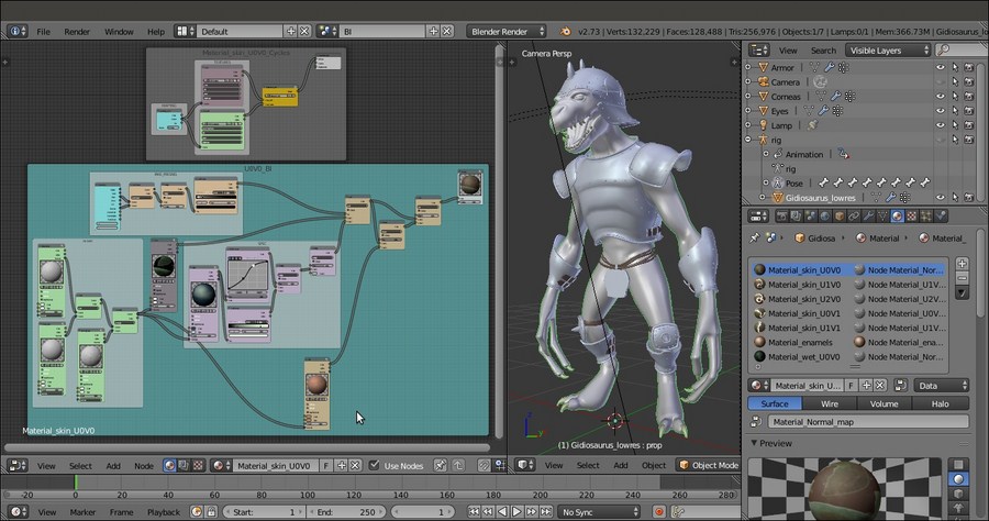
Two different sets of nodes for the same material
Getting ready
The first thing to do is to open the last saved blend file, add Frames to each material in the Node Editor window, and label them with the material name followed by the suffix _Cycles; this is to later distinguish them from the material we will build for BI.
Therefore:
- Start Blender and load the
Gidiosaurus_shaders_Cycles.blendfile. - In the Outliner, select the Gidiosaurus_lowres mesh, go to the Material window and click on the
Material_skin_U0V0slot; put the mouse pointer inside the Node Editor window and press Shift + A to add a Frame (Shift + A | Layout | Frame). - Press A to select all the nodes (the added Frame, already selected, becomes the active one) and then press Ctrl + P to parent them to the active Frame.
- Select only the Frame and press N to call the Properties sidepanel; in the Label slot under the Name subpanel, type Material_skin_U0V0_Cycles, then go down to the Properties subpanel and increase the Label Size to 40.
- Repeat the procedure for all the Cycles' Gidiosaurus_lowres materials, for the Eyes and Corneas and for the Armor materials.
So, for example, the
Material_skin_U0V0, in the Node Editor window, becomes this:A "framed" Cycles material
Also, the
Material_wet_U0V0, becomes this:Another "framed" Cycles material
Note that the name of the material is the same as before, the only difference is that a Frame labeled with the _Cycles suffix has been added in the Node Editor window to visually group all the Cycles' nodes that are a constituent of the shader.
- Now go to the Scene data block button on the main top header; left-click on it and rename the Scene label as Cycles:
Renaming the Scene label
- Click on the + icon button to the right of the datablock name; in the pop-up little New Scene panel, select the Link Objects item:
Adding a new scene with linked objects
At this point we have created a new scene (automatically labeled as Cycles.001) that is sharing the same objects of the other (Cycles) scene (be aware of this: the objects in one scene are not a copy of the others, they are the same objects shared/linked between the two scenes); you can say which objects are actually linked from one scene to another, by their blue pivot point (for example, look at the highlighted pivot point of the Gidiosaurus_lowres object in the following screenshot):
A new scene with linked objects
The advantages of creating new scenes with linked objects are obvious: we can have totally different rendering engines, or different worlds or lamps, in the different scenes and use the same objects and meshes data; so, for example, any modification to a linked object in one scene will automatically be transferred to the other scenes.
Furthermore, avoid duplicating the objects for each scene; this will help to keep a small file size.
- Rename the scene from Cycles.001 to BI, then move to the Engine to use for rendering button a bit to the right and switch from Cycles Render to Blender Render.
Switching to the Blender Render engine and the "empty material" preview
- In the Outliner, select the Lamp (be sure to have enabled both the 11th and the 6th scene layers); go to the Object Data window, set the energy to 14.000 and the color to R 1.000, G 1.000, B 0.650; under the Shadow subpanel, enable the Buffer Shadow item, Filter Type to Gauss, Soft = 12.000, Size = 4000, and Samples = 16. Set Clip Start = 9.000 and Clip End = 19.000.
- Go to the World window and enable the Ambient Occlusion by checking the item in the subpanel of the same name; leave the Blend Mode to Add and set the Factor to 0.35.
- Go further down to the Gather subpanel and click on the Approximate button: check the Pixel Cache item and then check also the Falloff checkbox under the Attenuation item; set the Strength to 0.900.
- Enable the Indirect Lighting item just above and set the Factor to 0.65.
These World settings are to obtain a sort of Global Illumination effect in the Blender Render engine; to learn more, have a look at http://www.blender.org/manual/render/blender_render/world/index.html.
- Save the file as
Gidiosaurus_shaders_Blender_Internal.blend.
Let's start with the first top Gidiosaurus skin material, so:
- Be sure to have the Gidiosaurus_lowres object selected and, back in the Material window, click on the
Material_skin_U0V0slot. - Put the mouse pointer inside the Node Editor window and press Shift + A (Shift + A | Input | Material) to add a Material node to the window; then press again Shift + A and add an Output node (Shift + A | Output | Output):
Adding a first material node in the Node Editor window
- Connect the Color output of the Material node to the Color input socket of the Output node:
Connecting the material node to the output node
- Now click on the New button on the Material node to create a new default Blender Internal material:
Creating a default "mono" material by clicking on the New button in the material node
- In the Properties sidepanel of the Node Editor window (N key to call it) label the Material node as COL and assign a color.
If you look now at the Material window, close to the right side of the material datablock (the name of the material), there is an already enabled and squared button with the symbol of the nodes.
In our case, that button is already enabled because we are already using material nodes; because it's enabled, a second material datablock slot has appeared just further down: that's the datablock slot for any node selected inside the Node Editor window and that is part of a material node.
The purpose of this second datablock slot is to let us know which material is the selected one and we are therefore going to edit it by tweaking all the values in the subpanels below.
- Go to the Material window to find the second material name slot: rename the material selected in the Node Editor window as
Material_U0V0_Col; you can do the same thing by clicking on the name datablock on the COL node interface.The corresponding datablock slots in the node interface and in the Material window
- In the Node Editor window, or in the N Properties sidepanel, deselect the Specular item.
- Go to the top of the Material window and click on the pin icon to the left of the contest; by doing this only the selected material is shown in the window.
- Go to the Diffuse sidepanel and click on the Diffuse Shader Model button to select the Oren-Nayar item; then go down to the Shading subpanel and enable the Cubic Interpolation item:
The Specular item to be disabled in the Node Editor window and the shader's parameters to be tweaked in the Material window
- At this point, press Shift + B to draw a box around the character's head in the Camera view and then zoom to it. If your computer is powerful enough to allow you to work without slowing down, put the mouse pointer inside the 3D viewport and press Shift + Z to start the Rendered preview; in any case, you can easily enable or disable the preview every time you need it:
Cropping and starting the rendered preview
- Click on the Texture window icon at the top right of the main Properties panel, just above the contest, be sure to have the first top texture slot selected and click on the New button to automatically load a default Image or Movie texture panel:
Adding a first texture slot to the material
- Collapse the Preview and the Colors subpanels, which at this moment we don't need, and click on the double little arrows to the left side of the New/Open buttons in the Image subpanel (remember that we have already loaded inside the blend file all the image textures we need, because of the Cycles shaders!): in the pop-up menu, select the
U0V0_col.pngitem:Selecting the right image texture from the drop-down list
- Go further down to find the Mapping subpanel: be sure to have the Coordinates set to UV, the Projection to Flat (default settings) and click on the Map empty slot to select the UVMap item.
Selecting the right UV coordinates mapping
- Go even further down to find the Influence subpanel: be sure that the diffuse Color channel is the one enabled and that the slider is set to 1.000 (again, default settings):
The Influence settings subpanel for the texture
- Scroll back to the top of the Texture window and click on the Unique datablock ID name slot, where the generic Texture name is written; rename it as
U0V0(as you can see in the following screenshot, this is the name that also appears in the textures list window):Renaming the texture datablock
- Now click on the empty second slot: again, click on the New button, click on the double arrows and this time load the image
U0V0_scales.png. - In the Unique datablock ID name slot, rename it as
U0V0_scales_col_add1.Adding a new texture slot, loading a new image texture and renaming it accordingly
- In the Input Color Space slot under the Image subpanel, change the default sRGB to Non-Color; then, scroll down to the Mapping panel to set the UVMap coordinates item and then go to the Influence subpanel: leave the Color channel enabled but move the slider to the lower value of 0.350, then change the Blend Type to Linear Light (for the Blender Internal materials, the Blend Type works as the layer system of a 2D image editor such as Photoshop or Gimp); enable the RGB to Intensity item and change the pink color to R 0.130, G 0.051, B 0.030.
Tweaking the Influence settings for the second texture
- Go up to expand the Colors subpanel: set the Brightness and the Contrast to 0.500, to make the texture less bright and less contrasted. Go down to the Image Sampling subpanel and set the Filter Size to 3.00, to blur the image (values beyond 1.00 start to blur the image more and more):
Modifying the appearance of the second image texture
- Select the third empty texture slot and repeat the procedure, again loading the
U0V0_scales.pngimage; in the Unique datablock ID name slot, rename it asU0V0_scales_col_add2. - Scroll down to the Mapping panel to set the UVMap coordinates item and then in the Influence subpanel, leave the Color channel enabled at value 1.000 but change the Blend Type to Subtract. Set the Brightness to 0.100 and the Contrast to 1.500. Again, set the Filter Size to 3.00.
- Select the fourth texture slot, load again the
U0V0_scales.pngimage, rename itU0V0_scales_col, set the UVMap coordinates layer, Color = 1.000 and Blend Type = Divide:Adding more texture slots with different settings
- Select the fifth texture slot, load the
vcol.pngimage again, rename itvcol, set the UVMap_norm coordinates layer, Color = 0.800 and Blend Type = Screen:Adding the baked Vertex Color image texture as well
At this point we have completed the first component of the skin shader, that is, the diffuse color component; in the following F12 render you can see the final result:
The completed diffuse color component of the Blender Internal skin material
Note that this F12 render result is quite different from the Rendered real-time preview; this is probably due to the complexity of using several textures inside a node material system with the (sadly) bad real-time viewport performances of Blender.
Now, we can carry on with building the second component of the shader, the glossy component.
- Put the mouse pointer inside the Node Editor window and add a new Material node (Shift + A | Input | Material); label it as SPEC and then click on the New button to create a new material: rename it
Material_U0V0_Spec. - Go to the Material window; in the Diffuse sidepanel, change the shader model to Oren-Nayar, then change the color to a deep blue R 0.020, G 0.051, B 0.089.
- Enable the Ramp item: in the slider, switch the positions of the two color stops (that is: white color stop to position 0.000 and black color stop to position 1.000), then select the white color stop; put the mouse on the deep blue color slot of the Diffuse subpanel and press Ctrl + C to copy it; put the mouse pointer on the color slot of the selected color stop and press Ctrl + V to paste the deep blue color.
- Click on the Diffuse Ramp Input button at the bottom of the subpanel to select the Normal item and on the Diffuse Ramp Blend button to the right to select the Multiply item:
The "Material_U0V0_Spec", to be used inside the "Material_skin_U0V0" node material
- Scroll down to the Specular subpanel: change the color to a light blue R 0.474, G 0.642, B 0.683; set the Intensity to 0.600 and the Hardness to 10.
- Enable the Ramp item: select the white color stop and change the color to R 0.761, G 1.000, B 0.708, then set the Diffuse Ramp Input button to Normal and the Diffuse Ramp Blend to Color.
- Go to the Shading subpanel and enable the Cubic Interpolation item:
Setting the parameters of the specularity component
- Go to the Textures window; select the top first empty texture slot and click on the New button. Load the image
vcol.png, rename the ID datablock asvcol_lightand go to the Colors subpanel: set the Brightness to 1.150 and the Contrast to 0.850. Go down to the Mapping subpanel and set the UVMap_norm coordinates layer, then in the Influence subpanel disable the diffuse Color channel and enable both the Intensity and the Hardness channels under Specular; set the Blend Type to Value:The settings for the specularity first texture
- Go to the second slot and load the image
U0V0_scales.png; rename it asU0V0_scales_hardness, in the Mapping subpanel, set the UVMap coordinates layer, in the Influence subpanel disable the diffuse Color and enable the Hardness channel under Specular to 0.125. In the Image Sampling subpanel set the Filter Size to 5.00.Re-using the "U0V0_scales.png" image texture for the specularity hardness
- In the third slot load the image
Ice_Lake_Ref.hdr, a free high dynamic range image licensed under the Creative Commons Attribution-Noncommercial-Share Alike 3.0 License from the sIBL Archive (http://www.hdrlabs.com/sibl/archive.html); there is a reason we are now using the hdr image, and it's explained in the How it works… section. - Rename the image ID datablock as
env_refl_skinand in the Colors subpanel, set the Brightness to 1.200 and the Contrast to 1.500; go to the Mapping subpanel and set the Texture Coordinates to Reflection. Down in the Influence subpanel, enable both the Intensity channel under Diffuse and Specular and set their sliders to 0.500; enable also, the Color channel under Specular and set the sliders of both the Color channels to 0.500 as well. Set the Blend Type to Screen, enable the RGB to Intensity item and set the color to the same deep blue of the diffuse color (R 0.020, G 0.051, B 0.089):Using the environment hdr image as reflection map
If you want to see the effect of the single components in the Rendered preview as we build the shader, just temporarily disconnect the COL node link to the Output node and replace it with the Color output of the SPEC node (in this case):
Testing the specularity component material in the rendered preview
- At this point, add a MixRGB node (Shift + A | Color | MixRGB) and move it on the link connecting the COL node to the Output node, to automatically paste it between them; then connect the Color output of the SPEC node to the Color2 input socket of the MixRGB node, set the Blend Type of this latter node to Add and its Fac value to 1.000:
Finally adding the specularity component to the diffuse component
- Add a RGB Curves node (Shift + A | Color | RGB Curves) and a ColorRamp node (Shift + A | Converter | ColorRamp); paste the RGB Curves node between the SPEC and the MixRGB node, then connect the Color output of the SPEC node also to the ColorRamp input socket:
Adding new nodes
- Press Shift + D to duplicate the MixRGB node, change the Blend Type of the duplicate to Multiply and paste it between the RGB Curves and the first Add-MixRGB nodes: set the Fac value to 0.500. Connect the Color output of the ColorRamp node to the Color2 input socket of the Multiply-MixRGB node.
- Press Shift + D to duplicate the Multiply-MixRGB node and paste the duplicate between the first Multiply-MixRGB node and the Add-MixRGB node. Set the Fac value of the last Multiply-MixRGB node to 0.600 and the Color2 to R 0.347, G 0.462, B 0.386.
- Go to the RGB Curves node and left-click inside the interface window to add a point; set its coordinates to X = 0.38636 and Y = 0.36875. Add a second point and set its coordinates to X = 0.64545 and Y = 0.84375.
- Go to the ColorRamp node and set the Interpolation to B-Spline, then move the black color stop to position 0.195 and the white color stop to position 0.800:
Tweaking the specularity component through the new nodes
- Add a Geometry node (Shift + A | Input | Geometry), a Vector Math node (Shift + A | Converter | Vector Math), a Math node (Shift + A | Converter | Math), and a ColorRamp node (Shift + A | Converter | ColorRamp).
- Add a Frame (Shift + A | Layout | Frame), label it as FAKE_FRESNEL and parent the last four added nodes to it.
- Set the Operation of the Vector Math node to Dot Product, then connect the View output of the Geometry node to the first Vector input socket of the Vector Math node, and the Normal output of the Geometry node to the second Vector input socket of the Vector Math node.
- Connect the Value output of the Dot Product node to the first Value input socket of the Math node; set the Operation of this latter node to Multiply and the second Value to 0.100.
- Connect the output of the Math node to the Fac input socket of the ColorRamp node; set the Interpolation of this latter node to B-Spline, then move the black color stop to position 0.150 and the white color stop to position 0.000.
- Connect the Color output of the ColorRamp node to the Fac input socket of the Add-MixRGB node:
Adding the output of a fake Fresnel as factor for the blending of the two components
Let's do a F12 rendering to see the result so far:
The F12 rendered result so far
- Now, select the COL material node and press Shift + D to duplicate it. Label the duplicated one as SSS, then through the Node Editor window, enable the Specular item. Click on the 2 icon button to the right side of the material name datablock to make it single user and rename the new copy of the material as
Material_U0V0_SSS. - Go to the Material window and change the Diffuse Shader Model to Minnaert and the Diffuse color to R 0.439, G 0.216, B 0.141. Move down to the Specular subpanel and change the color to the same R 0.439, G 0.216, B 0.141 brownish hue (copy and paste), then set the Intensity to 0.600 and the Hardness to 12.
- Go down to the Subsurface Scattering subpanel and enable it by checking the checkbox: set the IOR value to 3.840, the Scale to 0.001, copy and paste the brownish color also in the scattering color slot, set the Color slider to 0.000 and the Texture slider to 1.000. Set the RGB Radius: R 9.436, G 3.348, B 1.790.
- Go to the Texture window and set to 0.300 the Color channel sliders of the
U0V0,U0V0_scales_col_add2, andU0V0_scales_coltexture slots, then set to 0.117 the Color channel slider of theU0V0_scales_col_add1texture slot. - Select the last
vcoltexture slot and click on the X icon (Unlink datablock) button to clear it; click on the double little arrows to the left side of the New button and select thevcol_lightitem from the pop-up menu. Set the Mapping to UVMap_norm, and under the Influence subpanel, the Color of Diffuse to 0.267 and the Blend Type to Screen.Testing the output of the SSS component material
- Add a new MixRGB node (Shift + A | Color | MixRGB), paste it between the Add-MixRGB and the Output node and set the Fac value to 0.250.
- Press Shift + D to duplicate this Mix-MixRGB node; change the Blend Type of the duplicated one to Screen, set the Fac value to 1.000 and connect the output of the Add-MixRGB also to the Color1 input socket of the Screen-MixRGB node; connect the output of the SSS node to the Color2 input socket of the Screen-MixRGB node.
- Connect the output of the Screen-MixRGB node to the Color2 input socket of the first Mix-MixRGB node.
Adding the SSS component to the rest of the shader
- Add a new Material node (Shift + A | Input | Material) and click on the New button to create a new material; label the node as Scales_bump and rename the material as
Material_U0V0_Scales_bump. - In the Material window set the Diffuse Shader Model to Oren-Nayar and the Specular Shader Model to Blinn, Intensity = 0.100 and Hardness = 5. In the Shading subpanel enable the Cubic Interpolation item.
- Go to the Texture window and in the first slot load the
U0V0_scales.pngimage; rename the ID datablock asU0V0_scales_bump1. In the Image Sampling subpanel set the Filter Size to 5.00, the Mapping to UVMap and in the Influence subpanel disable the Color channel and enable the Normal channel under Geometry: set the slider to 0.100 and go to the bottom to click on the Bump Method slot and select Best Quality:The bump material node
- Go back to the top of the panel and click on the big black arrow to the right of the texture window; select the Copy Texture Slot Settings item.
- Select the empty second texture slot and click on New to add a generic texture, then click again on the black arrow to select the Paste Texture Slot Settings item.
- In the ID datablock slot, click on the 2 icon button to make it single user and rename it
U0V0_scales_bump2. - Go down to the Image Sampling subpanel and set the Filter Size to 1.00, then go down to the Influence subpanel and set the Normal slider to 0.200.
Copying and pasting a texture slot
- Press Shift + D to duplicate the node; make the material of the duplicated one single user and rename it as
Material_Clouds_noise, then label the node as Clouds_noise. - In the Texture window, delete (unlink)
U0V0_scales_bump1andU0V0_scales_bump2, and then select the first slot and click on the New button: change the automaticTexture.001ID datablock name withClouds_noise, click on the Type button and in the pop-up menu select the Clouds item. - In the Colors subpanel set the Brightness to 0.500 and the Contrast to 1.500, in the Mapping subpanel set the UVMap_scales coordinates layer, in the Clouds subpanel switch from Grayscale to Color, set the Size to 0.20, the Depth to 0.3 and the Nabla to 0.05.
- In the Influence subpanel disable the Color channel and enable the Normal channel under Geometry: set the slider to 0.250 and go to the bottom to click on the Bump Method slot and select Best Quality:
The second bump material node
- Press Shift + D to duplicate the Scales_bump node; make the material of the duplicated one single user and rename it as
Material_Normal_map, then label the node as Normal_map as well. - In the Texture window, delete (unlink) the
U0V0_scales_bump1andU0V0_scales_bump2; select the first slot and click on the New button: change the automaticTexture.001ID datablock name tonormaland then load thenorm.pngimage. - In the Mapping subpanel set the UVMap_norm coordinates layer, then go to the Image Sampling subpanel and enable the Normal Map item; go to the Influence subpanel, disable the Color channel and enable the Normal channel: set the slider to 1.000 (higher values don't have an effect with normal maps in Blender Internal).
The normal map material node
- Add a Vector Math node (Shift + A | Converter | Vector Math) and connect the Normal (blue) output of the Scales_bump node to the first Vector input socket of the Vector Math node, and the Normal output of the Clouds_noise node to the second Vector input socket.
- Press Shift + D to duplicate the Vector Math node, set the Operation of the duplicate to Average and connect the Vector output of the Add-Vector Math node to the first Vector input socket of the Average-Vector Math node, and the Normal output of the Normal_map node to the second Vector input socket.
Connecting the outputs of the three bump nodes
- Connect the Vector output of the Average-Vector Math node to the Normal input sockets of the COL, SPEC, and SSS material nodes.
- Add frames everywhere to make things clear but especially to visually group and separate the nodes of the Blender Internal material from the Cycles ones.
The completed "U0V0_BI" node material
- Save the file.
You have probably noticed that a few of the nodes we can find in the Cycles material system are also available for the material nodes in Blender Internal; sadly, some are still missing (and probably forever will be), as, for example, a Fresnel node that, in fact, we had to approximate with a combination of other different nodes.
Anyway, although not all the same nodes are at our disposal, we had enough of them to try to obtain a result as close as possible as the result we obtained in the Cycles material (in the previous Chapter 12, Creating the Materials in Cycles).
Note
One thing you should absolutely keep in mind when loading the textures into the material nodes in Blender Internal is their order in the texture stack. This is important and must be taken into consideration according to the result we need, because a texture can totally overwrite the texture in the above slot (with the default Mix blend type) but can also be added, subtracted, multiplied, divided, and so on; the textures stack works the same as the layer stack system of a 2D graphic editor (Gimp, for instance), with the order from the top to the bottom and the different blending options (the Blend Type items).
Having said that, let's see the steps:
- From step 1 to step 9 we created a basic Blender Internal material node by using both the Node Editor and the Material window.
- From step 10 to step 23 we assigned the proper textures to the basic material node that becomes, in this case, the
Material_U0V0_Col, the basic diffuse color component of the shader.These steps have been described in the most detailed way possible because they are the same steps for all the textures added to the materials; of course, the values and the settings can be different, but basically:
- We add a texture (image or procedural)
- We set a mapping orientation
- We set the influence value on the selected channel (also more than one at a time)
- Because the same texture can be used (with different settings) more than once, we always rename the Unique datablock ID name to make them easily recognizable in the pop-up menu list.
- The Filter Size value in the Image Sampling subpanel is really useful for blurring an image texture: a value of 1.00 is the default sharpness, while a higher value makes the image more and more blurred.
- From step 24 to step 30 we created the glossy/specular
Material_U0V0_Specnode. - From step 31 to step 34 we added the textures to the
Material_U0V0_Specmaterial. This material should represent the glossy/specular/mirror component of the shader, that is probably the most important thing for obtaining a correct visual result; in Cycles the Glossy BSDF shader node provides the result perfectly, while in Blender Internal, we have two options: one, by enabling the (slow and imperfect) internal ray-tracing Mirror item, or by faking it. We faked it by setting an image (the same hdr we'll use in the next chapter in the World both for Cycles and BI) on the Reflection channel of the shader, hence giving the impression of an environment (slightly) mirrored by the character's skin. - At step 35 we added together the outputs of the COL and of the SPEC nodes.
- From step 36 to step 40 we tweaked the output of the SPEC nodes to obtain a more realistic output/distribution of the glossiness on the mesh's surface, trying to mimic, as much as possible, the glossy output of the Cycles shader version.
- From step 41 to step 46 we built a fake Fresnel to work as a factor for the blending of the glossy and the diffuse components; this works by calculating the dot product of the vectors of the point of view and the mesh's normals. Be aware that it isn't actually working as the real Fresnel node that you find in Cycles, and that it has several limitations. By varying the second Value of the Math node and/or the black color stop position of the ColorRamp node, we can obtain several nice effects in some way visually similar to the real output. If you are wondering why we don't use the output of a BI material with a Fresnel diffuse shader model, sadly it doesn't seem to work correctly (actually, it doesn't seem to work at all).
- From step 47 to step 51 we built the SSS material node by duplicating the COL node, making a new copy of the material and renaming it as
Material_U0V0_SSS, then enabling Subsurface Scattering and modifying the influence values of the textures; the values of the subsurface scattering (IOR, Scale, RGB Radius), instead, were borrowed from the Cycles version of the shader. - From step 52 to step 54 we added the output of the SSS node to the rest of the shader by using a Blend Type set to Screen plus a Mix one set to a low Fac value; basically, the exact copy of what we did in Cycles.
- From step 55 to step 71 we created the bump pattern, divided into three different material nodes to give us more flexibility in adding and averaging them together in a way that is as similar as possible to Cycles:
The F12 rendered final result in Blender Internal
The other missing shaders for the Gidiosaurus skin are solved in exactly the same way we used in the previous chapter for the other Cycles skin shaders: by selecting the entire BI frame with all the parented nodes and pressing Ctrl + C to copy them, then selecting the different material slots and pressing Ctrl + V to paste everything; in Blender Internal, we have to make the single materials inside the nodes single user one by one and then substitute the textures according to the UDIM tile the material corresponds to (U1V0_col.png, U1V0_scales.png, U2V0_col.png, and so on).
So, in the end, each material will have two sets of nodes, one for the Cycles shader and one for the Blender Internal shader, and each one works under the respective render engine; this will be useful, as we'll see in the next chapter, for the rendering stage.
Two different sets of nodes for the same material
How to do it…
Let's start with the first top Gidiosaurus skin material, so:
- Be sure to have the Gidiosaurus_lowres object selected and, back in the Material window, click on the
Material_skin_U0V0slot. - Put the mouse pointer inside the Node Editor window and press Shift + A (Shift + A | Input | Material) to add a Material node to the window; then press again Shift + A and add an Output node (Shift + A | Output | Output):
Adding a first material node in the Node Editor window
- Connect the Color output of the Material node to the Color input socket of the Output node:
Connecting the material node to the output node
- Now click on the New button on the Material node to create a new default Blender Internal material:
Creating a default "mono" material by clicking on the New button in the material node
- In the Properties sidepanel of the Node Editor window (N key to call it) label the Material node as COL and assign a color.
If you look now at the Material window, close to the right side of the material datablock (the name of the material), there is an already enabled and squared button with the symbol of the nodes.
In our case, that button is already enabled because we are already using material nodes; because it's enabled, a second material datablock slot has appeared just further down: that's the datablock slot for any node selected inside the Node Editor window and that is part of a material node.
The purpose of this second datablock slot is to let us know which material is the selected one and we are therefore going to edit it by tweaking all the values in the subpanels below.
- Go to the Material window to find the second material name slot: rename the material selected in the Node Editor window as
Material_U0V0_Col; you can do the same thing by clicking on the name datablock on the COL node interface.The corresponding datablock slots in the node interface and in the Material window
- In the Node Editor window, or in the N Properties sidepanel, deselect the Specular item.
- Go to the top of the Material window and click on the pin icon to the left of the contest; by doing this only the selected material is shown in the window.
- Go to the Diffuse sidepanel and click on the Diffuse Shader Model button to select the Oren-Nayar item; then go down to the Shading subpanel and enable the Cubic Interpolation item:
The Specular item to be disabled in the Node Editor window and the shader's parameters to be tweaked in the Material window
- At this point, press Shift + B to draw a box around the character's head in the Camera view and then zoom to it. If your computer is powerful enough to allow you to work without slowing down, put the mouse pointer inside the 3D viewport and press Shift + Z to start the Rendered preview; in any case, you can easily enable or disable the preview every time you need it:
Cropping and starting the rendered preview
- Click on the Texture window icon at the top right of the main Properties panel, just above the contest, be sure to have the first top texture slot selected and click on the New button to automatically load a default Image or Movie texture panel:
Adding a first texture slot to the material
- Collapse the Preview and the Colors subpanels, which at this moment we don't need, and click on the double little arrows to the left side of the New/Open buttons in the Image subpanel (remember that we have already loaded inside the blend file all the image textures we need, because of the Cycles shaders!): in the pop-up menu, select the
U0V0_col.pngitem:Selecting the right image texture from the drop-down list
- Go further down to find the Mapping subpanel: be sure to have the Coordinates set to UV, the Projection to Flat (default settings) and click on the Map empty slot to select the UVMap item.
Selecting the right UV coordinates mapping
- Go even further down to find the Influence subpanel: be sure that the diffuse Color channel is the one enabled and that the slider is set to 1.000 (again, default settings):
The Influence settings subpanel for the texture
- Scroll back to the top of the Texture window and click on the Unique datablock ID name slot, where the generic Texture name is written; rename it as
U0V0(as you can see in the following screenshot, this is the name that also appears in the textures list window):Renaming the texture datablock
- Now click on the empty second slot: again, click on the New button, click on the double arrows and this time load the image
U0V0_scales.png. - In the Unique datablock ID name slot, rename it as
U0V0_scales_col_add1.Adding a new texture slot, loading a new image texture and renaming it accordingly
- In the Input Color Space slot under the Image subpanel, change the default sRGB to Non-Color; then, scroll down to the Mapping panel to set the UVMap coordinates item and then go to the Influence subpanel: leave the Color channel enabled but move the slider to the lower value of 0.350, then change the Blend Type to Linear Light (for the Blender Internal materials, the Blend Type works as the layer system of a 2D image editor such as Photoshop or Gimp); enable the RGB to Intensity item and change the pink color to R 0.130, G 0.051, B 0.030.
Tweaking the Influence settings for the second texture
- Go up to expand the Colors subpanel: set the Brightness and the Contrast to 0.500, to make the texture less bright and less contrasted. Go down to the Image Sampling subpanel and set the Filter Size to 3.00, to blur the image (values beyond 1.00 start to blur the image more and more):
Modifying the appearance of the second image texture
- Select the third empty texture slot and repeat the procedure, again loading the
U0V0_scales.pngimage; in the Unique datablock ID name slot, rename it asU0V0_scales_col_add2. - Scroll down to the Mapping panel to set the UVMap coordinates item and then in the Influence subpanel, leave the Color channel enabled at value 1.000 but change the Blend Type to Subtract. Set the Brightness to 0.100 and the Contrast to 1.500. Again, set the Filter Size to 3.00.
- Select the fourth texture slot, load again the
U0V0_scales.pngimage, rename itU0V0_scales_col, set the UVMap coordinates layer, Color = 1.000 and Blend Type = Divide:Adding more texture slots with different settings
- Select the fifth texture slot, load the
vcol.pngimage again, rename itvcol, set the UVMap_norm coordinates layer, Color = 0.800 and Blend Type = Screen:Adding the baked Vertex Color image texture as well
At this point we have completed the first component of the skin shader, that is, the diffuse color component; in the following F12 render you can see the final result:
The completed diffuse color component of the Blender Internal skin material
Note that this F12 render result is quite different from the Rendered real-time preview; this is probably due to the complexity of using several textures inside a node material system with the (sadly) bad real-time viewport performances of Blender.
Now, we can carry on with building the second component of the shader, the glossy component.
- Put the mouse pointer inside the Node Editor window and add a new Material node (Shift + A | Input | Material); label it as SPEC and then click on the New button to create a new material: rename it
Material_U0V0_Spec. - Go to the Material window; in the Diffuse sidepanel, change the shader model to Oren-Nayar, then change the color to a deep blue R 0.020, G 0.051, B 0.089.
- Enable the Ramp item: in the slider, switch the positions of the two color stops (that is: white color stop to position 0.000 and black color stop to position 1.000), then select the white color stop; put the mouse on the deep blue color slot of the Diffuse subpanel and press Ctrl + C to copy it; put the mouse pointer on the color slot of the selected color stop and press Ctrl + V to paste the deep blue color.
- Click on the Diffuse Ramp Input button at the bottom of the subpanel to select the Normal item and on the Diffuse Ramp Blend button to the right to select the Multiply item:
The "Material_U0V0_Spec", to be used inside the "Material_skin_U0V0" node material
- Scroll down to the Specular subpanel: change the color to a light blue R 0.474, G 0.642, B 0.683; set the Intensity to 0.600 and the Hardness to 10.
- Enable the Ramp item: select the white color stop and change the color to R 0.761, G 1.000, B 0.708, then set the Diffuse Ramp Input button to Normal and the Diffuse Ramp Blend to Color.
- Go to the Shading subpanel and enable the Cubic Interpolation item:
Setting the parameters of the specularity component
- Go to the Textures window; select the top first empty texture slot and click on the New button. Load the image
vcol.png, rename the ID datablock asvcol_lightand go to the Colors subpanel: set the Brightness to 1.150 and the Contrast to 0.850. Go down to the Mapping subpanel and set the UVMap_norm coordinates layer, then in the Influence subpanel disable the diffuse Color channel and enable both the Intensity and the Hardness channels under Specular; set the Blend Type to Value:The settings for the specularity first texture
- Go to the second slot and load the image
U0V0_scales.png; rename it asU0V0_scales_hardness, in the Mapping subpanel, set the UVMap coordinates layer, in the Influence subpanel disable the diffuse Color and enable the Hardness channel under Specular to 0.125. In the Image Sampling subpanel set the Filter Size to 5.00.Re-using the "U0V0_scales.png" image texture for the specularity hardness
- In the third slot load the image
Ice_Lake_Ref.hdr, a free high dynamic range image licensed under the Creative Commons Attribution-Noncommercial-Share Alike 3.0 License from the sIBL Archive (http://www.hdrlabs.com/sibl/archive.html); there is a reason we are now using the hdr image, and it's explained in the How it works… section. - Rename the image ID datablock as
env_refl_skinand in the Colors subpanel, set the Brightness to 1.200 and the Contrast to 1.500; go to the Mapping subpanel and set the Texture Coordinates to Reflection. Down in the Influence subpanel, enable both the Intensity channel under Diffuse and Specular and set their sliders to 0.500; enable also, the Color channel under Specular and set the sliders of both the Color channels to 0.500 as well. Set the Blend Type to Screen, enable the RGB to Intensity item and set the color to the same deep blue of the diffuse color (R 0.020, G 0.051, B 0.089):Using the environment hdr image as reflection map
If you want to see the effect of the single components in the Rendered preview as we build the shader, just temporarily disconnect the COL node link to the Output node and replace it with the Color output of the SPEC node (in this case):
Testing the specularity component material in the rendered preview
- At this point, add a MixRGB node (Shift + A | Color | MixRGB) and move it on the link connecting the COL node to the Output node, to automatically paste it between them; then connect the Color output of the SPEC node to the Color2 input socket of the MixRGB node, set the Blend Type of this latter node to Add and its Fac value to 1.000:
Finally adding the specularity component to the diffuse component
- Add a RGB Curves node (Shift + A | Color | RGB Curves) and a ColorRamp node (Shift + A | Converter | ColorRamp); paste the RGB Curves node between the SPEC and the MixRGB node, then connect the Color output of the SPEC node also to the ColorRamp input socket:
Adding new nodes
- Press Shift + D to duplicate the MixRGB node, change the Blend Type of the duplicate to Multiply and paste it between the RGB Curves and the first Add-MixRGB nodes: set the Fac value to 0.500. Connect the Color output of the ColorRamp node to the Color2 input socket of the Multiply-MixRGB node.
- Press Shift + D to duplicate the Multiply-MixRGB node and paste the duplicate between the first Multiply-MixRGB node and the Add-MixRGB node. Set the Fac value of the last Multiply-MixRGB node to 0.600 and the Color2 to R 0.347, G 0.462, B 0.386.
- Go to the RGB Curves node and left-click inside the interface window to add a point; set its coordinates to X = 0.38636 and Y = 0.36875. Add a second point and set its coordinates to X = 0.64545 and Y = 0.84375.
- Go to the ColorRamp node and set the Interpolation to B-Spline, then move the black color stop to position 0.195 and the white color stop to position 0.800:
Tweaking the specularity component through the new nodes
- Add a Geometry node (Shift + A | Input | Geometry), a Vector Math node (Shift + A | Converter | Vector Math), a Math node (Shift + A | Converter | Math), and a ColorRamp node (Shift + A | Converter | ColorRamp).
- Add a Frame (Shift + A | Layout | Frame), label it as FAKE_FRESNEL and parent the last four added nodes to it.
- Set the Operation of the Vector Math node to Dot Product, then connect the View output of the Geometry node to the first Vector input socket of the Vector Math node, and the Normal output of the Geometry node to the second Vector input socket of the Vector Math node.
- Connect the Value output of the Dot Product node to the first Value input socket of the Math node; set the Operation of this latter node to Multiply and the second Value to 0.100.
- Connect the output of the Math node to the Fac input socket of the ColorRamp node; set the Interpolation of this latter node to B-Spline, then move the black color stop to position 0.150 and the white color stop to position 0.000.
- Connect the Color output of the ColorRamp node to the Fac input socket of the Add-MixRGB node:
Adding the output of a fake Fresnel as factor for the blending of the two components
Let's do a F12 rendering to see the result so far:
The F12 rendered result so far
- Now, select the COL material node and press Shift + D to duplicate it. Label the duplicated one as SSS, then through the Node Editor window, enable the Specular item. Click on the 2 icon button to the right side of the material name datablock to make it single user and rename the new copy of the material as
Material_U0V0_SSS. - Go to the Material window and change the Diffuse Shader Model to Minnaert and the Diffuse color to R 0.439, G 0.216, B 0.141. Move down to the Specular subpanel and change the color to the same R 0.439, G 0.216, B 0.141 brownish hue (copy and paste), then set the Intensity to 0.600 and the Hardness to 12.
- Go down to the Subsurface Scattering subpanel and enable it by checking the checkbox: set the IOR value to 3.840, the Scale to 0.001, copy and paste the brownish color also in the scattering color slot, set the Color slider to 0.000 and the Texture slider to 1.000. Set the RGB Radius: R 9.436, G 3.348, B 1.790.
- Go to the Texture window and set to 0.300 the Color channel sliders of the
U0V0,U0V0_scales_col_add2, andU0V0_scales_coltexture slots, then set to 0.117 the Color channel slider of theU0V0_scales_col_add1texture slot. - Select the last
vcoltexture slot and click on the X icon (Unlink datablock) button to clear it; click on the double little arrows to the left side of the New button and select thevcol_lightitem from the pop-up menu. Set the Mapping to UVMap_norm, and under the Influence subpanel, the Color of Diffuse to 0.267 and the Blend Type to Screen.Testing the output of the SSS component material
- Add a new MixRGB node (Shift + A | Color | MixRGB), paste it between the Add-MixRGB and the Output node and set the Fac value to 0.250.
- Press Shift + D to duplicate this Mix-MixRGB node; change the Blend Type of the duplicated one to Screen, set the Fac value to 1.000 and connect the output of the Add-MixRGB also to the Color1 input socket of the Screen-MixRGB node; connect the output of the SSS node to the Color2 input socket of the Screen-MixRGB node.
- Connect the output of the Screen-MixRGB node to the Color2 input socket of the first Mix-MixRGB node.
Adding the SSS component to the rest of the shader
- Add a new Material node (Shift + A | Input | Material) and click on the New button to create a new material; label the node as Scales_bump and rename the material as
Material_U0V0_Scales_bump. - In the Material window set the Diffuse Shader Model to Oren-Nayar and the Specular Shader Model to Blinn, Intensity = 0.100 and Hardness = 5. In the Shading subpanel enable the Cubic Interpolation item.
- Go to the Texture window and in the first slot load the
U0V0_scales.pngimage; rename the ID datablock asU0V0_scales_bump1. In the Image Sampling subpanel set the Filter Size to 5.00, the Mapping to UVMap and in the Influence subpanel disable the Color channel and enable the Normal channel under Geometry: set the slider to 0.100 and go to the bottom to click on the Bump Method slot and select Best Quality:The bump material node
- Go back to the top of the panel and click on the big black arrow to the right of the texture window; select the Copy Texture Slot Settings item.
- Select the empty second texture slot and click on New to add a generic texture, then click again on the black arrow to select the Paste Texture Slot Settings item.
- In the ID datablock slot, click on the 2 icon button to make it single user and rename it
U0V0_scales_bump2. - Go down to the Image Sampling subpanel and set the Filter Size to 1.00, then go down to the Influence subpanel and set the Normal slider to 0.200.
Copying and pasting a texture slot
- Press Shift + D to duplicate the node; make the material of the duplicated one single user and rename it as
Material_Clouds_noise, then label the node as Clouds_noise. - In the Texture window, delete (unlink)
U0V0_scales_bump1andU0V0_scales_bump2, and then select the first slot and click on the New button: change the automaticTexture.001ID datablock name withClouds_noise, click on the Type button and in the pop-up menu select the Clouds item. - In the Colors subpanel set the Brightness to 0.500 and the Contrast to 1.500, in the Mapping subpanel set the UVMap_scales coordinates layer, in the Clouds subpanel switch from Grayscale to Color, set the Size to 0.20, the Depth to 0.3 and the Nabla to 0.05.
- In the Influence subpanel disable the Color channel and enable the Normal channel under Geometry: set the slider to 0.250 and go to the bottom to click on the Bump Method slot and select Best Quality:
The second bump material node
- Press Shift + D to duplicate the Scales_bump node; make the material of the duplicated one single user and rename it as
Material_Normal_map, then label the node as Normal_map as well. - In the Texture window, delete (unlink) the
U0V0_scales_bump1andU0V0_scales_bump2; select the first slot and click on the New button: change the automaticTexture.001ID datablock name tonormaland then load thenorm.pngimage. - In the Mapping subpanel set the UVMap_norm coordinates layer, then go to the Image Sampling subpanel and enable the Normal Map item; go to the Influence subpanel, disable the Color channel and enable the Normal channel: set the slider to 1.000 (higher values don't have an effect with normal maps in Blender Internal).
The normal map material node
- Add a Vector Math node (Shift + A | Converter | Vector Math) and connect the Normal (blue) output of the Scales_bump node to the first Vector input socket of the Vector Math node, and the Normal output of the Clouds_noise node to the second Vector input socket.
- Press Shift + D to duplicate the Vector Math node, set the Operation of the duplicate to Average and connect the Vector output of the Add-Vector Math node to the first Vector input socket of the Average-Vector Math node, and the Normal output of the Normal_map node to the second Vector input socket.
Connecting the outputs of the three bump nodes
- Connect the Vector output of the Average-Vector Math node to the Normal input sockets of the COL, SPEC, and SSS material nodes.
- Add frames everywhere to make things clear but especially to visually group and separate the nodes of the Blender Internal material from the Cycles ones.
The completed "U0V0_BI" node material
- Save the file.
You have probably noticed that a few of the nodes we can find in the Cycles material system are also available for the material nodes in Blender Internal; sadly, some are still missing (and probably forever will be), as, for example, a Fresnel node that, in fact, we had to approximate with a combination of other different nodes.
Anyway, although not all the same nodes are at our disposal, we had enough of them to try to obtain a result as close as possible as the result we obtained in the Cycles material (in the previous Chapter 12, Creating the Materials in Cycles).
Note
One thing you should absolutely keep in mind when loading the textures into the material nodes in Blender Internal is their order in the texture stack. This is important and must be taken into consideration according to the result we need, because a texture can totally overwrite the texture in the above slot (with the default Mix blend type) but can also be added, subtracted, multiplied, divided, and so on; the textures stack works the same as the layer stack system of a 2D graphic editor (Gimp, for instance), with the order from the top to the bottom and the different blending options (the Blend Type items).
Having said that, let's see the steps:
- From step 1 to step 9 we created a basic Blender Internal material node by using both the Node Editor and the Material window.
- From step 10 to step 23 we assigned the proper textures to the basic material node that becomes, in this case, the
Material_U0V0_Col, the basic diffuse color component of the shader.These steps have been described in the most detailed way possible because they are the same steps for all the textures added to the materials; of course, the values and the settings can be different, but basically:
- We add a texture (image or procedural)
- We set a mapping orientation
- We set the influence value on the selected channel (also more than one at a time)
- Because the same texture can be used (with different settings) more than once, we always rename the Unique datablock ID name to make them easily recognizable in the pop-up menu list.
- The Filter Size value in the Image Sampling subpanel is really useful for blurring an image texture: a value of 1.00 is the default sharpness, while a higher value makes the image more and more blurred.
- From step 24 to step 30 we created the glossy/specular
Material_U0V0_Specnode. - From step 31 to step 34 we added the textures to the
Material_U0V0_Specmaterial. This material should represent the glossy/specular/mirror component of the shader, that is probably the most important thing for obtaining a correct visual result; in Cycles the Glossy BSDF shader node provides the result perfectly, while in Blender Internal, we have two options: one, by enabling the (slow and imperfect) internal ray-tracing Mirror item, or by faking it. We faked it by setting an image (the same hdr we'll use in the next chapter in the World both for Cycles and BI) on the Reflection channel of the shader, hence giving the impression of an environment (slightly) mirrored by the character's skin. - At step 35 we added together the outputs of the COL and of the SPEC nodes.
- From step 36 to step 40 we tweaked the output of the SPEC nodes to obtain a more realistic output/distribution of the glossiness on the mesh's surface, trying to mimic, as much as possible, the glossy output of the Cycles shader version.
- From step 41 to step 46 we built a fake Fresnel to work as a factor for the blending of the glossy and the diffuse components; this works by calculating the dot product of the vectors of the point of view and the mesh's normals. Be aware that it isn't actually working as the real Fresnel node that you find in Cycles, and that it has several limitations. By varying the second Value of the Math node and/or the black color stop position of the ColorRamp node, we can obtain several nice effects in some way visually similar to the real output. If you are wondering why we don't use the output of a BI material with a Fresnel diffuse shader model, sadly it doesn't seem to work correctly (actually, it doesn't seem to work at all).
- From step 47 to step 51 we built the SSS material node by duplicating the COL node, making a new copy of the material and renaming it as
Material_U0V0_SSS, then enabling Subsurface Scattering and modifying the influence values of the textures; the values of the subsurface scattering (IOR, Scale, RGB Radius), instead, were borrowed from the Cycles version of the shader. - From step 52 to step 54 we added the output of the SSS node to the rest of the shader by using a Blend Type set to Screen plus a Mix one set to a low Fac value; basically, the exact copy of what we did in Cycles.
- From step 55 to step 71 we created the bump pattern, divided into three different material nodes to give us more flexibility in adding and averaging them together in a way that is as similar as possible to Cycles:
The F12 rendered final result in Blender Internal
The other missing shaders for the Gidiosaurus skin are solved in exactly the same way we used in the previous chapter for the other Cycles skin shaders: by selecting the entire BI frame with all the parented nodes and pressing Ctrl + C to copy them, then selecting the different material slots and pressing Ctrl + V to paste everything; in Blender Internal, we have to make the single materials inside the nodes single user one by one and then substitute the textures according to the UDIM tile the material corresponds to (U1V0_col.png, U1V0_scales.png, U2V0_col.png, and so on).
So, in the end, each material will have two sets of nodes, one for the Cycles shader and one for the Blender Internal shader, and each one works under the respective render engine; this will be useful, as we'll see in the next chapter, for the rendering stage.
Two different sets of nodes for the same material
How it works…
You have probably noticed that a few of the nodes we can find in the Cycles material system are also available for the material nodes in Blender Internal; sadly, some are still missing (and probably forever will be), as, for example, a Fresnel node that, in fact, we had to approximate with a combination of other different nodes.
Anyway, although not all the same nodes are at our disposal, we had enough of them to try to obtain a result as close as possible as the result we obtained in the Cycles material (in the previous Chapter 12, Creating the Materials in Cycles).
Note
One thing you should absolutely keep in mind when loading the textures into the material nodes in Blender Internal is their order in the texture stack. This is important and must be taken into consideration according to the result we need, because a texture can totally overwrite the texture in the above slot (with the default Mix blend type) but can also be added, subtracted, multiplied, divided, and so on; the textures stack works the same as the layer stack system of a 2D graphic editor (Gimp, for instance), with the order from the top to the bottom and the different blending options (the Blend Type items).
Having said that, let's see the steps:
- From step 1 to step 9 we created a basic Blender Internal material node by using both the Node Editor and the Material window.
- From step 10 to step 23 we assigned the proper textures to the basic material node that becomes, in this case, the
Material_U0V0_Col, the basic diffuse color component of the shader.These steps have been described in the most detailed way possible because they are the same steps for all the textures added to the materials; of course, the values and the settings can be different, but basically:
- We add a texture (image or procedural)
- We set a mapping orientation
- We set the influence value on the selected channel (also more than one at a time)
- Because the same texture can be used (with different settings) more than once, we always rename the Unique datablock ID name to make them easily recognizable in the pop-up menu list.
- The Filter Size value in the Image Sampling subpanel is really useful for blurring an image texture: a value of 1.00 is the default sharpness, while a higher value makes the image more and more blurred.
- From step 24 to step 30 we created the glossy/specular
Material_U0V0_Specnode. - From step 31 to step 34 we added the textures to the
Material_U0V0_Specmaterial. This material should represent the glossy/specular/mirror component of the shader, that is probably the most important thing for obtaining a correct visual result; in Cycles the Glossy BSDF shader node provides the result perfectly, while in Blender Internal, we have two options: one, by enabling the (slow and imperfect) internal ray-tracing Mirror item, or by faking it. We faked it by setting an image (the same hdr we'll use in the next chapter in the World both for Cycles and BI) on the Reflection channel of the shader, hence giving the impression of an environment (slightly) mirrored by the character's skin. - At step 35 we added together the outputs of the COL and of the SPEC nodes.
- From step 36 to step 40 we tweaked the output of the SPEC nodes to obtain a more realistic output/distribution of the glossiness on the mesh's surface, trying to mimic, as much as possible, the glossy output of the Cycles shader version.
- From step 41 to step 46 we built a fake Fresnel to work as a factor for the blending of the glossy and the diffuse components; this works by calculating the dot product of the vectors of the point of view and the mesh's normals. Be aware that it isn't actually working as the real Fresnel node that you find in Cycles, and that it has several limitations. By varying the second Value of the Math node and/or the black color stop position of the ColorRamp node, we can obtain several nice effects in some way visually similar to the real output. If you are wondering why we don't use the output of a BI material with a Fresnel diffuse shader model, sadly it doesn't seem to work correctly (actually, it doesn't seem to work at all).
- From step 47 to step 51 we built the SSS material node by duplicating the COL node, making a new copy of the material and renaming it as
Material_U0V0_SSS, then enabling Subsurface Scattering and modifying the influence values of the textures; the values of the subsurface scattering (IOR, Scale, RGB Radius), instead, were borrowed from the Cycles version of the shader. - From step 52 to step 54 we added the output of the SSS node to the rest of the shader by using a Blend Type set to Screen plus a Mix one set to a low Fac value; basically, the exact copy of what we did in Cycles.
- From step 55 to step 71 we created the bump pattern, divided into three different material nodes to give us more flexibility in adding and averaging them together in a way that is as similar as possible to Cycles:
The F12 rendered final result in Blender Internal
The other missing shaders for the Gidiosaurus skin are solved in exactly the same way we used in the previous chapter for the other Cycles skin shaders: by selecting the entire BI frame with all the parented nodes and pressing Ctrl + C to copy them, then selecting the different material slots and pressing Ctrl + V to paste everything; in Blender Internal, we have to make the single materials inside the nodes single user one by one and then substitute the textures according to the UDIM tile the material corresponds to (U1V0_col.png, U1V0_scales.png, U2V0_col.png, and so on).
So, in the end, each material will have two sets of nodes, one for the Cycles shader and one for the Blender Internal shader, and each one works under the respective render engine; this will be useful, as we'll see in the next chapter, for the rendering stage.
Two different sets of nodes for the same material
There's more…
The other missing shaders for the Gidiosaurus skin are solved in exactly the same way we used in the previous chapter for the other Cycles skin shaders: by selecting the entire BI frame with all the parented nodes and pressing Ctrl + C to copy them, then selecting the different material slots and pressing Ctrl + V to paste everything; in Blender Internal, we have to make the single materials inside the nodes single user one by one and then substitute the textures according to the UDIM tile the material corresponds to (U1V0_col.png, U1V0_scales.png, U2V0_col.png, and so on).
So, in the end, each material will have two sets of nodes, one for the Cycles shader and one for the Blender Internal shader, and each one works under the respective render engine; this will be useful, as we'll see in the next chapter, for the rendering stage.
Two different sets of nodes for the same material
We'll now see how to make the shaders for the Gidiosaurus's eyes; they are composed of two objects, the Corneas and the Eyes objects, so let's start with the first one.
Enable the 6th and the 12th scene layers and select the Corneas object; in the Outliner, disable the Eyes object's visibility in the viewport to hide it, put the mouse pointer inside the Camera view, zoom to one of the eyeballs and then start the Rendered preview.
Let's start to create the Corneas material:
- Put the mouse pointer in the Node Editor window and add: a Material node (Shift + A | Input | Material), a Geometry node (Shift + A | Input | Geometry), a MixRGB node (Shift + A | Color | MixRGB) and an Output node (Shift + A | Output | Output).
- Connect the Color output of the Material node to the Color input socket of the Output node, then click on the New button on the Material node to create a new material and rename it
Cornea_bump. - In the Material window, expand the Render Pipeline Options subpanel and enable the Transparency item; in the Diffuse subpanel set the shader model to Oren-Nayar and the color to a bright orange = R 0.930, G 0.386, B 0.082. In the Specular subpanel set the shader model to WardIso and the Slope to 0.070. In the Shading subpanel enable the Cubic Interpolation item.
- Go down to expand the Transparency subpanel; set the Fresnel value to 1.380 and the Blend to 1.700.
- Go further down to enable the Mirror item in the subpanel with the same name, set the Reflectivity to 0.200, the Fresnel to 1.380 and the Blend to 1.500.
- Go to the Texture window and in the first slot load the image
eyeball_col.jpg, rename the ID datablock aseyeball_coland set the UVMap.001 as the coordinates layer; in the Influence subpanel set the diffuse Color channel to 0.200 and the specular Color channel to 0.200 as well, set the Blend Type to Color. - In the second texture slot load the image
eyeball_bump.jpg, rename the ID datablock asEyeball_bump, set UVMap.001 as the coordinates layer and disable the Color channel to enable the Normal one at 0.007; set the Bump Method to Best Quality:
The "Corneas" material nodes
- Paste the MixRGB node between the Material and the Output nodes; then, connect the Vertex Color output of the Geometry node to the Fac input socket of the MixRGB node. Click on the last empty field at the bottom of the Geometry node to select the Col item from the pop-up list (it's the name of the Vertex Color layer that has been created, and mentioned, at the beginning of the Building the eyes' shaders in Cycles recipe in Chapter 12, Creating the Materials in Cycles).

The gray color of the Color2 socket of the MixRGB node showing in the rendered preview at the location established by the Vertex Color layer output used as factor
In the preceding screenshot, the effect of the Vertex Color layer is visible: the two gray dots on the eyeballs are actually the crystalline lens areas filled, only at the moment, with the gray color of the empty Color2 input socket of the MixRGB node.
- Press Shift + D to duplicate the Material node, click on the 2 icon button to the right side of the name datablock of the duplicated node to make the material single user, rename the new material, simply,
Corneaand, in the Texture window, select the second slot texture,eyeball_bump, to click on the X icon button and delete it. - Connect the Color output of the second Material node to the Color2 input socket of the MixRGB node.

The completed "Corneas" material
Now, go to the Outliner and enable the Eyes object visibility in the viewport to show it:
- With the Corneas object still selected, put the mouse pointer on the first Material node in the Node Editor window and press Ctrl + C to copy it.
- Select the Eyes object and, in the Material window, select the
Eyeballsmaterial slot; put the mouse pointer in the Node Editor window and press Ctrl + V to paste the material node we copied before. - Click on the 2 icon button to make the material single user and rename it
Eyes. Add an Output node (Shift + A | Output | Output) and connect the Color output of the Eyes material node to the Color input socket of the Output node. - Go to the Material window and disable the Transparency item in the Render Pipeline Options subpanel; go to the Mirror subpanel and disable it.
- Enable the Subsurface Scattering subpanel: set the IOR to 1.340, the Scale to 0.001, the scattering color to the orange R 0.930, G 0.386, B 0.082 and the RGB Radius to the R 9.436, G 3.348, B 1.790 values.

The "Eyeballs" material SSS settings
- Go to the Texture window; select the
eyeball_coltexture and set the diffuse Color to 0.855, disable the specular Color channel and set the Blend Type to Linear Light; select theeyeball_bumptexture and set the Normal channel slider to 0.005.
The "Eyeballs" material texture settings
Now let's see the iris:
- Box-select both the
Eyesmaterial node and the connected Output node and press Ctrl + C to copy them; go to the Material window and select theIrisesmaterial slot, then put the mouse pointer in the Node Editor window and press Ctrl + V to paste them. - Make the duplicated node's material single user and rename it
Iris; change the Diffuse subpanel color to R 0.429, G 0.153, B 0.000, then go to the Shading subpanel and set the Emit value to 0.07. Go to the Subsurface Scattering subpanel and change the scattering color to R 0.220, G 0.033, B 0.032. - Go to the Texture window and delete (unlink) the two texture slots. In the first slot, load the image
iris_col.jpg, rename the ID datablockiris_col, and set UVMap.001 as the UV coordinates layer. In the second slot, load the imageiris_bump.jpg, rename asiris_bump, set UVMap.001 as the UV coordinates layer and in the Influence subpanel disable the Color channel and enable the specular Intensity and Hardness channels with value 1.000, then enable also the Normal channel with value 1.000. Set the Bump Method to Best Quality. - In the third texture slot, load again the
iris_bump.jpgimage; rename the ID datablock asiris_ST. In the Image Sampling subpanel, under Alpha, disable the Use item and enable the Calculate item. Set the UVMap.001 coordinates layer and in the Influence subpanel disable the Color channel and enable only the Stencil item at the bottom:
The "Irises" material and the Stencil item
- In the fourth texture slot, load the
iris_col.jpgimage, rename the ID datablock asiris_emit. Set the UVMap.001 coordinates layer and in the Influence subpanel disable the Color channel and enable the Emit channel at value 1.000.
The "Irises" material emitting (fake) light
Regarding the
Pupilsmaterial, it's a simple basic material with pure black as Diffuse color and the Intensity slider under the Specular subpanel set to 0.000 to be totally matte. - Save the file.
For the Corneas object: we created two copies of the same transparent material, but then we removed the bump from one of them, because usually a cornea has bumps due to the veins on the eyeball but not on the crystalline lens, that is smooth; the two materials are mixed, exactly as in the Cycles version, through the output of the Col Vertex Color layer.
Regarding the Irises material: the iris_ST texture, set as a stencil map, works as a mask for the following texture to appear through its black areas.
Although it could have been solved by simply leaving a blank material slot, I assigned a black matte material to the pupils; I preferred to assign a material anyway, to avoid possible issues in the following stages such as, for example, in the rendering of the character against an alpha backdrop, of the separated passes and in the compositing.
Note that the Corneas is the only material where I enabled the ray-tracing mirror, which in the character's skin and in the armor are instead faked, to obtain faster rendering times (the eyes are really a small surface to be rendered).
Getting ready
Enable the 6th and the 12th scene layers and select the Corneas object; in the Outliner, disable the Eyes object's visibility in the viewport to hide it, put the mouse pointer inside the Camera view, zoom to one of the eyeballs and then start the Rendered preview.
Let's start to create the Corneas material:
- Put the mouse pointer in the Node Editor window and add: a Material node (Shift + A | Input | Material), a Geometry node (Shift + A | Input | Geometry), a MixRGB node (Shift + A | Color | MixRGB) and an Output node (Shift + A | Output | Output).
- Connect the Color output of the Material node to the Color input socket of the Output node, then click on the New button on the Material node to create a new material and rename it
Cornea_bump. - In the Material window, expand the Render Pipeline Options subpanel and enable the Transparency item; in the Diffuse subpanel set the shader model to Oren-Nayar and the color to a bright orange = R 0.930, G 0.386, B 0.082. In the Specular subpanel set the shader model to WardIso and the Slope to 0.070. In the Shading subpanel enable the Cubic Interpolation item.
- Go down to expand the Transparency subpanel; set the Fresnel value to 1.380 and the Blend to 1.700.
- Go further down to enable the Mirror item in the subpanel with the same name, set the Reflectivity to 0.200, the Fresnel to 1.380 and the Blend to 1.500.
- Go to the Texture window and in the first slot load the image
eyeball_col.jpg, rename the ID datablock aseyeball_coland set the UVMap.001 as the coordinates layer; in the Influence subpanel set the diffuse Color channel to 0.200 and the specular Color channel to 0.200 as well, set the Blend Type to Color. - In the second texture slot load the image
eyeball_bump.jpg, rename the ID datablock asEyeball_bump, set UVMap.001 as the coordinates layer and disable the Color channel to enable the Normal one at 0.007; set the Bump Method to Best Quality:The "Corneas" material nodes
- Paste the MixRGB node between the Material and the Output nodes; then, connect the Vertex Color output of the Geometry node to the Fac input socket of the MixRGB node. Click on the last empty field at the bottom of the Geometry node to select the Col item from the pop-up list (it's the name of the Vertex Color layer that has been created, and mentioned, at the beginning of the Building the eyes' shaders in Cycles recipe in Chapter 12, Creating the Materials in Cycles).
The gray color of the Color2 socket of the MixRGB node showing in the rendered preview at the location established by the Vertex Color layer output used as factor
In the preceding screenshot, the effect of the Vertex Color layer is visible: the two gray dots on the eyeballs are actually the crystalline lens areas filled, only at the moment, with the gray color of the empty Color2 input socket of the MixRGB node.
- Press Shift + D to duplicate the Material node, click on the 2 icon button to the right side of the name datablock of the duplicated node to make the material single user, rename the new material, simply,
Corneaand, in the Texture window, select the second slot texture,eyeball_bump, to click on the X icon button and delete it. - Connect the Color output of the second Material node to the Color2 input socket of the MixRGB node.
The completed "Corneas" material
Now, go to the Outliner and enable the Eyes object visibility in the viewport to show it:
- With the Corneas object still selected, put the mouse pointer on the first Material node in the Node Editor window and press Ctrl + C to copy it.
- Select the Eyes object and, in the Material window, select the
Eyeballsmaterial slot; put the mouse pointer in the Node Editor window and press Ctrl + V to paste the material node we copied before. - Click on the 2 icon button to make the material single user and rename it
Eyes. Add an Output node (Shift + A | Output | Output) and connect the Color output of the Eyes material node to the Color input socket of the Output node. - Go to the Material window and disable the Transparency item in the Render Pipeline Options subpanel; go to the Mirror subpanel and disable it.
- Enable the Subsurface Scattering subpanel: set the IOR to 1.340, the Scale to 0.001, the scattering color to the orange R 0.930, G 0.386, B 0.082 and the RGB Radius to the R 9.436, G 3.348, B 1.790 values.
The "Eyeballs" material SSS settings
- Go to the Texture window; select the
eyeball_coltexture and set the diffuse Color to 0.855, disable the specular Color channel and set the Blend Type to Linear Light; select theeyeball_bumptexture and set the Normal channel slider to 0.005.The "Eyeballs" material texture settings
Now let's see the iris:
- Box-select both the
Eyesmaterial node and the connected Output node and press Ctrl + C to copy them; go to the Material window and select theIrisesmaterial slot, then put the mouse pointer in the Node Editor window and press Ctrl + V to paste them. - Make the duplicated node's material single user and rename it
Iris; change the Diffuse subpanel color to R 0.429, G 0.153, B 0.000, then go to the Shading subpanel and set the Emit value to 0.07. Go to the Subsurface Scattering subpanel and change the scattering color to R 0.220, G 0.033, B 0.032. - Go to the Texture window and delete (unlink) the two texture slots. In the first slot, load the image
iris_col.jpg, rename the ID datablockiris_col, and set UVMap.001 as the UV coordinates layer. In the second slot, load the imageiris_bump.jpg, rename asiris_bump, set UVMap.001 as the UV coordinates layer and in the Influence subpanel disable the Color channel and enable the specular Intensity and Hardness channels with value 1.000, then enable also the Normal channel with value 1.000. Set the Bump Method to Best Quality. - In the third texture slot, load again the
iris_bump.jpgimage; rename the ID datablock asiris_ST. In the Image Sampling subpanel, under Alpha, disable the Use item and enable the Calculate item. Set the UVMap.001 coordinates layer and in the Influence subpanel disable the Color channel and enable only the Stencil item at the bottom:The "Irises" material and the Stencil item
- In the fourth texture slot, load the
iris_col.jpgimage, rename the ID datablock asiris_emit. Set the UVMap.001 coordinates layer and in the Influence subpanel disable the Color channel and enable the Emit channel at value 1.000.The "Irises" material emitting (fake) light
Regarding the
Pupilsmaterial, it's a simple basic material with pure black as Diffuse color and the Intensity slider under the Specular subpanel set to 0.000 to be totally matte. - Save the file.
For the Corneas object: we created two copies of the same transparent material, but then we removed the bump from one of them, because usually a cornea has bumps due to the veins on the eyeball but not on the crystalline lens, that is smooth; the two materials are mixed, exactly as in the Cycles version, through the output of the Col Vertex Color layer.
Regarding the Irises material: the iris_ST texture, set as a stencil map, works as a mask for the following texture to appear through its black areas.
Although it could have been solved by simply leaving a blank material slot, I assigned a black matte material to the pupils; I preferred to assign a material anyway, to avoid possible issues in the following stages such as, for example, in the rendering of the character against an alpha backdrop, of the separated passes and in the compositing.
Note that the Corneas is the only material where I enabled the ray-tracing mirror, which in the character's skin and in the armor are instead faked, to obtain faster rendering times (the eyes are really a small surface to be rendered).
How to do it…
Let's start to create the Corneas material:
- Put the mouse pointer in the Node Editor window and add: a Material node (Shift + A | Input | Material), a Geometry node (Shift + A | Input | Geometry), a MixRGB node (Shift + A | Color | MixRGB) and an Output node (Shift + A | Output | Output).
- Connect the Color output of the Material node to the Color input socket of the Output node, then click on the New button on the Material node to create a new material and rename it
Cornea_bump. - In the Material window, expand the Render Pipeline Options subpanel and enable the Transparency item; in the Diffuse subpanel set the shader model to Oren-Nayar and the color to a bright orange = R 0.930, G 0.386, B 0.082. In the Specular subpanel set the shader model to WardIso and the Slope to 0.070. In the Shading subpanel enable the Cubic Interpolation item.
- Go down to expand the Transparency subpanel; set the Fresnel value to 1.380 and the Blend to 1.700.
- Go further down to enable the Mirror item in the subpanel with the same name, set the Reflectivity to 0.200, the Fresnel to 1.380 and the Blend to 1.500.
- Go to the Texture window and in the first slot load the image
eyeball_col.jpg, rename the ID datablock aseyeball_coland set the UVMap.001 as the coordinates layer; in the Influence subpanel set the diffuse Color channel to 0.200 and the specular Color channel to 0.200 as well, set the Blend Type to Color. - In the second texture slot load the image
eyeball_bump.jpg, rename the ID datablock asEyeball_bump, set UVMap.001 as the coordinates layer and disable the Color channel to enable the Normal one at 0.007; set the Bump Method to Best Quality:The "Corneas" material nodes
- Paste the MixRGB node between the Material and the Output nodes; then, connect the Vertex Color output of the Geometry node to the Fac input socket of the MixRGB node. Click on the last empty field at the bottom of the Geometry node to select the Col item from the pop-up list (it's the name of the Vertex Color layer that has been created, and mentioned, at the beginning of the Building the eyes' shaders in Cycles recipe in Chapter 12, Creating the Materials in Cycles).
The gray color of the Color2 socket of the MixRGB node showing in the rendered preview at the location established by the Vertex Color layer output used as factor
In the preceding screenshot, the effect of the Vertex Color layer is visible: the two gray dots on the eyeballs are actually the crystalline lens areas filled, only at the moment, with the gray color of the empty Color2 input socket of the MixRGB node.
- Press Shift + D to duplicate the Material node, click on the 2 icon button to the right side of the name datablock of the duplicated node to make the material single user, rename the new material, simply,
Corneaand, in the Texture window, select the second slot texture,eyeball_bump, to click on the X icon button and delete it. - Connect the Color output of the second Material node to the Color2 input socket of the MixRGB node.
The completed "Corneas" material
Now, go to the Outliner and enable the Eyes object visibility in the viewport to show it:
- With the Corneas object still selected, put the mouse pointer on the first Material node in the Node Editor window and press Ctrl + C to copy it.
- Select the Eyes object and, in the Material window, select the
Eyeballsmaterial slot; put the mouse pointer in the Node Editor window and press Ctrl + V to paste the material node we copied before. - Click on the 2 icon button to make the material single user and rename it
Eyes. Add an Output node (Shift + A | Output | Output) and connect the Color output of the Eyes material node to the Color input socket of the Output node. - Go to the Material window and disable the Transparency item in the Render Pipeline Options subpanel; go to the Mirror subpanel and disable it.
- Enable the Subsurface Scattering subpanel: set the IOR to 1.340, the Scale to 0.001, the scattering color to the orange R 0.930, G 0.386, B 0.082 and the RGB Radius to the R 9.436, G 3.348, B 1.790 values.
The "Eyeballs" material SSS settings
- Go to the Texture window; select the
eyeball_coltexture and set the diffuse Color to 0.855, disable the specular Color channel and set the Blend Type to Linear Light; select theeyeball_bumptexture and set the Normal channel slider to 0.005.The "Eyeballs" material texture settings
Now let's see the iris:
- Box-select both the
Eyesmaterial node and the connected Output node and press Ctrl + C to copy them; go to the Material window and select theIrisesmaterial slot, then put the mouse pointer in the Node Editor window and press Ctrl + V to paste them. - Make the duplicated node's material single user and rename it
Iris; change the Diffuse subpanel color to R 0.429, G 0.153, B 0.000, then go to the Shading subpanel and set the Emit value to 0.07. Go to the Subsurface Scattering subpanel and change the scattering color to R 0.220, G 0.033, B 0.032. - Go to the Texture window and delete (unlink) the two texture slots. In the first slot, load the image
iris_col.jpg, rename the ID datablockiris_col, and set UVMap.001 as the UV coordinates layer. In the second slot, load the imageiris_bump.jpg, rename asiris_bump, set UVMap.001 as the UV coordinates layer and in the Influence subpanel disable the Color channel and enable the specular Intensity and Hardness channels with value 1.000, then enable also the Normal channel with value 1.000. Set the Bump Method to Best Quality. - In the third texture slot, load again the
iris_bump.jpgimage; rename the ID datablock asiris_ST. In the Image Sampling subpanel, under Alpha, disable the Use item and enable the Calculate item. Set the UVMap.001 coordinates layer and in the Influence subpanel disable the Color channel and enable only the Stencil item at the bottom:The "Irises" material and the Stencil item
- In the fourth texture slot, load the
iris_col.jpgimage, rename the ID datablock asiris_emit. Set the UVMap.001 coordinates layer and in the Influence subpanel disable the Color channel and enable the Emit channel at value 1.000.The "Irises" material emitting (fake) light
Regarding the
Pupilsmaterial, it's a simple basic material with pure black as Diffuse color and the Intensity slider under the Specular subpanel set to 0.000 to be totally matte. - Save the file.
For the Corneas object: we created two copies of the same transparent material, but then we removed the bump from one of them, because usually a cornea has bumps due to the veins on the eyeball but not on the crystalline lens, that is smooth; the two materials are mixed, exactly as in the Cycles version, through the output of the Col Vertex Color layer.
Regarding the Irises material: the iris_ST texture, set as a stencil map, works as a mask for the following texture to appear through its black areas.
Although it could have been solved by simply leaving a blank material slot, I assigned a black matte material to the pupils; I preferred to assign a material anyway, to avoid possible issues in the following stages such as, for example, in the rendering of the character against an alpha backdrop, of the separated passes and in the compositing.
Note that the Corneas is the only material where I enabled the ray-tracing mirror, which in the character's skin and in the armor are instead faked, to obtain faster rendering times (the eyes are really a small surface to be rendered).
How it works…
For the Corneas object: we created two copies of the same transparent material, but then we removed the bump from one of them, because usually a cornea has bumps due to the veins on the eyeball but not on the crystalline lens, that is smooth; the two materials are mixed, exactly as in the Cycles version, through the output of the Col Vertex Color layer.
Regarding the Irises material: the iris_ST texture, set as a stencil map, works as a mask for the following texture to appear through its black areas.
Although it could have been solved by simply leaving a blank material slot, I assigned a black matte material to the pupils; I preferred to assign a material anyway, to avoid possible issues in the following stages such as, for example, in the rendering of the character against an alpha backdrop, of the separated passes and in the compositing.
Note that the Corneas is the only material where I enabled the ray-tracing mirror, which in the character's skin and in the armor are instead faked, to obtain faster rendering times (the eyes are really a small surface to be rendered).
We arrive finally at making the Armor shaders under the Blender Internal engine; we have four materials, here: the two UDIM plate shaders, the rivets shaders and the leather material for the tiers.
Enable the 6th and the 13th scene layers and select the Armor object; if your computer is powerful enough, use the Rendered preview while you are working.
Let's start with the first UDIM tile material creation, the main armor plates:
- Put the mouse pointer in the Node Editor window and add a Material node (Shift + A | Input | Material), a MixRGB node (Shift + A | Color | MixRGB) and an Output node (Shift + A | Output | Output). In the N Properties sidepanel, label the Material node as COL.
- Connect the Color output of the COL node to the Color input socket of the Output node, then click on the New button on the Material node to create a new material and rename it
Armor_U0V0_col; in the Node Editor window, disable the Specular item. - Go to the Material window and find the Diffuse subpanel; change the shader model to Oren-Nayar, set the color to R 0.817, G 0.879, B 1.000 and the Roughness value to 0.313.
- Go down to the Specular subpanel: set the shader model to WardIso, the Intensity to 1.000, the Slope to 0.270, and the color to R 0.381, G 0.527, B 0.497. In the Shading subpanel enable the Cubic Interpolation item.

Starting the "Armor_U0V0" material in Blender Internal
- Go to the Texture window and in the first texture slot, load the image
iron_U0V0.png; rename the ID datablock asiron_U0V0and set the UVMap coordinates layer, then go to the Influence subpanel and enable the diffuse Intensity channel at value 1.000, leave the Color channel as it is and change the Blend Type to Multiply:
Adding the first texture image
- In the second texture slot, load the image
vcol2.png, rename the ID datablock asvcol2and set the UVMap_norm UV coordinates layer; go to the Colors subpanel, enable the Ramp item and set the Interpolation to B-Spline, then move the black color stop to position 0.245 and the white color stop to position 0.755. In the Image Sampling subpanel set the Filter Size to 1.10 and in the Influence subpanel enable the diffuse Intensity channel at value 0.500, the diffuse Color channel at 0.300, set the Blend Type to Difference and enable the Negative item. - In the third texture slot, load the image
Ice_Lake_Ref.hdrand rename the ID datablock asenv_refl_armor. Set the Mapping coordinates to Reflection and, in the Image Sampling subpanel, the Filter Size to 6.00; in the Colors subpanel set the Brightness to 1.800 and the Contrast to 2.000, then move to the Influence subpanel and set both the diffuse Intensity and Color channels to 0.600 and the Blend Type to Multiply:
Adding the hdr image as reflection map
- Go to the Node Editor window and press Shift + D to duplicate the COL node; label the duplicate as SPEC1, then make the material single user and rename it
Armor_U0V0_spec1; disable the Diffuse item on the node interface and enable back, the Specular one. - Go to the Texture window; select the first
iron_U0V0texture slot and go straight to the Influence subpanel: disable the diffuse Intensity and Color channels and enable the specular Intensity, Color and Hardness channels at 1.000. Set the Blend Type to Mix. - Select the second
vcol2texture slot, disable the diffuse Intensity and Color channels and enable the specular Intensity channel at 0.300. - Select the third
env_refl_armortexture slot, disable the diffuse Intensity and Color channels and enable the specular Intensity and Color channels at 0.500. - Press Shift + D to duplicate the SPEC1 node and label the duplicated one as SPEC2: make the material single user and rename it as
Armor_U0V0_spec2. In the Material window go to the Specular subpanel and set the Slope to the maximum = 0.400. - Now, connect the Color output of the SPEC1 material node to the Color1 input socket of the MixRGB node and the Color output of the SPEC2 node to the Color2 input socket; set the Blend Type of the MixRGB node to Add and the Fac value to 0.900.
- Press Shift + D to duplicate the MixRGB node and connect the output of the first MixRGB node to the Color1 input socket of the duplicated MixRGB node, and the Color output of the COL node to the Color2 input socket; set the Fac value of the second MixRGB node to 1.000 and connect its output to the Color input socket of the Output node.

Adding the specular component
- Add a Math node (Shift + A | Converter | Math) and paste it between the two MixRGB nodes; set the Operation to Multiply and the second Value to 2.000.

Enhancing the specularity
- Add a Material node (Shift + A | Input | Material) and label it as BUMP; create a new material and rename it as
Armor_U0V0_normals; in the Shading subpanel enable the Cubic Interpolation item. - Go to the Texture window and in the first texture slot, load the image
norm2.png, rename the ID datablock asnorm2and in the Image Sampling subpanel enable the Normal Map item; in the Mapping subpanel set the UVMap_norm coordinates layer and in the Influence subpanel disable the Color channel and enable the Normal one at 0.500. - In the second texture slot, load the image
iron_U0V0.png, mapping to UVMap layer and Influence to Normal at 0.010; set the Bump Method to Best Quality. - Go to the Node Editor window and connect the Normal output of the BUMP node to the Normal input sockets of the SPEC1, SPEC2, and COL nodes.

Adding the bump pattern
- Box-select and press Ctrl + C to copy all these nodes, go to the Material window to select the
Armor_U1V0material slot and, back in the Node Editor window, paste the copied nodes: then make the materials inside the nodes as single users, rename them accordingly and go to the Texture window to substitute theiron_U0V0.pngimage with theiron_U1V0.pngimage. - Copy and paste again, the nodes for the
Armor_rivetsmaterial slot, but don't substitute the texture image: instead, simply delete the BUMP node, which wouldn't be of any use in such small parts.
The completed armor shaders in Blender Internal
- Save the file.
These shaders work, and have been built, exactly the same way as for the Gidiosaurus' skin and eyes; the only thing worth noting here is the order of the normal map and of the texture used for the bump pattern: in fact, to work together, in Blender Internal, the normal map must be placed higher in the texture stack, otherwise it will overwrite the effect of the bump map.
The Leather material is a simple basic Oren-Nayar diffuse shader with the usual WardIso specular shader model, provided with a bump effect obtained through a Voronoi procedural texture with default values, except for the Size.
Note that the Voronoi texture influences the Color channel with the Multiply blend type and the Normal channel with a negative low value to obtain an actual bulging out pattern, instead of a concave one; negative values, in fact, reverse the direction of the bump.
The size of the procedural texture along the three axes is also further tweaked in the Mapping subpanel, scaling the three axes differently to resemble the dimensions of the Texture Space (basically the mesh bounding box, than can be made visible through the subpanel of the same name in the Object Data window), in order to avoid stretching along the mesh.

The "Leather" material in Blender Internal
Note also that in all these Blender Internal materials, simple mono materials (as for example the Leather BI material shown here earlier) are loaded inside a Material node and then connected to an Output node in the Node Editor window even if this wouldn't be necessary for the material itself to work: but, to let the Blender Internal and the Cycles render engines work together (through the compositor, as we'll see in the next chapter), it is mandatory to have all the shaders as nodes.
Getting ready
Enable the 6th and the 13th scene layers and select the Armor object; if your computer is powerful enough, use the Rendered preview while you are working.
Let's start with the first UDIM tile material creation, the main armor plates:
- Put the mouse pointer in the Node Editor window and add a Material node (Shift + A | Input | Material), a MixRGB node (Shift + A | Color | MixRGB) and an Output node (Shift + A | Output | Output). In the N Properties sidepanel, label the Material node as COL.
- Connect the Color output of the COL node to the Color input socket of the Output node, then click on the New button on the Material node to create a new material and rename it
Armor_U0V0_col; in the Node Editor window, disable the Specular item. - Go to the Material window and find the Diffuse subpanel; change the shader model to Oren-Nayar, set the color to R 0.817, G 0.879, B 1.000 and the Roughness value to 0.313.
- Go down to the Specular subpanel: set the shader model to WardIso, the Intensity to 1.000, the Slope to 0.270, and the color to R 0.381, G 0.527, B 0.497. In the Shading subpanel enable the Cubic Interpolation item.
Starting the "Armor_U0V0" material in Blender Internal
- Go to the Texture window and in the first texture slot, load the image
iron_U0V0.png; rename the ID datablock asiron_U0V0and set the UVMap coordinates layer, then go to the Influence subpanel and enable the diffuse Intensity channel at value 1.000, leave the Color channel as it is and change the Blend Type to Multiply:Adding the first texture image
- In the second texture slot, load the image
vcol2.png, rename the ID datablock asvcol2and set the UVMap_norm UV coordinates layer; go to the Colors subpanel, enable the Ramp item and set the Interpolation to B-Spline, then move the black color stop to position 0.245 and the white color stop to position 0.755. In the Image Sampling subpanel set the Filter Size to 1.10 and in the Influence subpanel enable the diffuse Intensity channel at value 0.500, the diffuse Color channel at 0.300, set the Blend Type to Difference and enable the Negative item. - In the third texture slot, load the image
Ice_Lake_Ref.hdrand rename the ID datablock asenv_refl_armor. Set the Mapping coordinates to Reflection and, in the Image Sampling subpanel, the Filter Size to 6.00; in the Colors subpanel set the Brightness to 1.800 and the Contrast to 2.000, then move to the Influence subpanel and set both the diffuse Intensity and Color channels to 0.600 and the Blend Type to Multiply:Adding the hdr image as reflection map
- Go to the Node Editor window and press Shift + D to duplicate the COL node; label the duplicate as SPEC1, then make the material single user and rename it
Armor_U0V0_spec1; disable the Diffuse item on the node interface and enable back, the Specular one. - Go to the Texture window; select the first
iron_U0V0texture slot and go straight to the Influence subpanel: disable the diffuse Intensity and Color channels and enable the specular Intensity, Color and Hardness channels at 1.000. Set the Blend Type to Mix. - Select the second
vcol2texture slot, disable the diffuse Intensity and Color channels and enable the specular Intensity channel at 0.300. - Select the third
env_refl_armortexture slot, disable the diffuse Intensity and Color channels and enable the specular Intensity and Color channels at 0.500. - Press Shift + D to duplicate the SPEC1 node and label the duplicated one as SPEC2: make the material single user and rename it as
Armor_U0V0_spec2. In the Material window go to the Specular subpanel and set the Slope to the maximum = 0.400. - Now, connect the Color output of the SPEC1 material node to the Color1 input socket of the MixRGB node and the Color output of the SPEC2 node to the Color2 input socket; set the Blend Type of the MixRGB node to Add and the Fac value to 0.900.
- Press Shift + D to duplicate the MixRGB node and connect the output of the first MixRGB node to the Color1 input socket of the duplicated MixRGB node, and the Color output of the COL node to the Color2 input socket; set the Fac value of the second MixRGB node to 1.000 and connect its output to the Color input socket of the Output node.
Adding the specular component
- Add a Math node (Shift + A | Converter | Math) and paste it between the two MixRGB nodes; set the Operation to Multiply and the second Value to 2.000.
Enhancing the specularity
- Add a Material node (Shift + A | Input | Material) and label it as BUMP; create a new material and rename it as
Armor_U0V0_normals; in the Shading subpanel enable the Cubic Interpolation item. - Go to the Texture window and in the first texture slot, load the image
norm2.png, rename the ID datablock asnorm2and in the Image Sampling subpanel enable the Normal Map item; in the Mapping subpanel set the UVMap_norm coordinates layer and in the Influence subpanel disable the Color channel and enable the Normal one at 0.500. - In the second texture slot, load the image
iron_U0V0.png, mapping to UVMap layer and Influence to Normal at 0.010; set the Bump Method to Best Quality. - Go to the Node Editor window and connect the Normal output of the BUMP node to the Normal input sockets of the SPEC1, SPEC2, and COL nodes.
Adding the bump pattern
- Box-select and press Ctrl + C to copy all these nodes, go to the Material window to select the
Armor_U1V0material slot and, back in the Node Editor window, paste the copied nodes: then make the materials inside the nodes as single users, rename them accordingly and go to the Texture window to substitute theiron_U0V0.pngimage with theiron_U1V0.pngimage. - Copy and paste again, the nodes for the
Armor_rivetsmaterial slot, but don't substitute the texture image: instead, simply delete the BUMP node, which wouldn't be of any use in such small parts.The completed armor shaders in Blender Internal
- Save the file.
These shaders work, and have been built, exactly the same way as for the Gidiosaurus' skin and eyes; the only thing worth noting here is the order of the normal map and of the texture used for the bump pattern: in fact, to work together, in Blender Internal, the normal map must be placed higher in the texture stack, otherwise it will overwrite the effect of the bump map.
The Leather material is a simple basic Oren-Nayar diffuse shader with the usual WardIso specular shader model, provided with a bump effect obtained through a Voronoi procedural texture with default values, except for the Size.
Note that the Voronoi texture influences the Color channel with the Multiply blend type and the Normal channel with a negative low value to obtain an actual bulging out pattern, instead of a concave one; negative values, in fact, reverse the direction of the bump.
The size of the procedural texture along the three axes is also further tweaked in the Mapping subpanel, scaling the three axes differently to resemble the dimensions of the Texture Space (basically the mesh bounding box, than can be made visible through the subpanel of the same name in the Object Data window), in order to avoid stretching along the mesh.
The "Leather" material in Blender Internal
Note also that in all these Blender Internal materials, simple mono materials (as for example the Leather BI material shown here earlier) are loaded inside a Material node and then connected to an Output node in the Node Editor window even if this wouldn't be necessary for the material itself to work: but, to let the Blender Internal and the Cycles render engines work together (through the compositor, as we'll see in the next chapter), it is mandatory to have all the shaders as nodes.
How to do it…
Let's start with the first UDIM tile material creation, the main armor plates:
- Put the mouse pointer in the Node Editor window and add a Material node (Shift + A | Input | Material), a MixRGB node (Shift + A | Color | MixRGB) and an Output node (Shift + A | Output | Output). In the N Properties sidepanel, label the Material node as COL.
- Connect the Color output of the COL node to the Color input socket of the Output node, then click on the New button on the Material node to create a new material and rename it
Armor_U0V0_col; in the Node Editor window, disable the Specular item. - Go to the Material window and find the Diffuse subpanel; change the shader model to Oren-Nayar, set the color to R 0.817, G 0.879, B 1.000 and the Roughness value to 0.313.
- Go down to the Specular subpanel: set the shader model to WardIso, the Intensity to 1.000, the Slope to 0.270, and the color to R 0.381, G 0.527, B 0.497. In the Shading subpanel enable the Cubic Interpolation item.
Starting the "Armor_U0V0" material in Blender Internal
- Go to the Texture window and in the first texture slot, load the image
iron_U0V0.png; rename the ID datablock asiron_U0V0and set the UVMap coordinates layer, then go to the Influence subpanel and enable the diffuse Intensity channel at value 1.000, leave the Color channel as it is and change the Blend Type to Multiply:Adding the first texture image
- In the second texture slot, load the image
vcol2.png, rename the ID datablock asvcol2and set the UVMap_norm UV coordinates layer; go to the Colors subpanel, enable the Ramp item and set the Interpolation to B-Spline, then move the black color stop to position 0.245 and the white color stop to position 0.755. In the Image Sampling subpanel set the Filter Size to 1.10 and in the Influence subpanel enable the diffuse Intensity channel at value 0.500, the diffuse Color channel at 0.300, set the Blend Type to Difference and enable the Negative item. - In the third texture slot, load the image
Ice_Lake_Ref.hdrand rename the ID datablock asenv_refl_armor. Set the Mapping coordinates to Reflection and, in the Image Sampling subpanel, the Filter Size to 6.00; in the Colors subpanel set the Brightness to 1.800 and the Contrast to 2.000, then move to the Influence subpanel and set both the diffuse Intensity and Color channels to 0.600 and the Blend Type to Multiply:Adding the hdr image as reflection map
- Go to the Node Editor window and press Shift + D to duplicate the COL node; label the duplicate as SPEC1, then make the material single user and rename it
Armor_U0V0_spec1; disable the Diffuse item on the node interface and enable back, the Specular one. - Go to the Texture window; select the first
iron_U0V0texture slot and go straight to the Influence subpanel: disable the diffuse Intensity and Color channels and enable the specular Intensity, Color and Hardness channels at 1.000. Set the Blend Type to Mix. - Select the second
vcol2texture slot, disable the diffuse Intensity and Color channels and enable the specular Intensity channel at 0.300. - Select the third
env_refl_armortexture slot, disable the diffuse Intensity and Color channels and enable the specular Intensity and Color channels at 0.500. - Press Shift + D to duplicate the SPEC1 node and label the duplicated one as SPEC2: make the material single user and rename it as
Armor_U0V0_spec2. In the Material window go to the Specular subpanel and set the Slope to the maximum = 0.400. - Now, connect the Color output of the SPEC1 material node to the Color1 input socket of the MixRGB node and the Color output of the SPEC2 node to the Color2 input socket; set the Blend Type of the MixRGB node to Add and the Fac value to 0.900.
- Press Shift + D to duplicate the MixRGB node and connect the output of the first MixRGB node to the Color1 input socket of the duplicated MixRGB node, and the Color output of the COL node to the Color2 input socket; set the Fac value of the second MixRGB node to 1.000 and connect its output to the Color input socket of the Output node.
Adding the specular component
- Add a Math node (Shift + A | Converter | Math) and paste it between the two MixRGB nodes; set the Operation to Multiply and the second Value to 2.000.
Enhancing the specularity
- Add a Material node (Shift + A | Input | Material) and label it as BUMP; create a new material and rename it as
Armor_U0V0_normals; in the Shading subpanel enable the Cubic Interpolation item. - Go to the Texture window and in the first texture slot, load the image
norm2.png, rename the ID datablock asnorm2and in the Image Sampling subpanel enable the Normal Map item; in the Mapping subpanel set the UVMap_norm coordinates layer and in the Influence subpanel disable the Color channel and enable the Normal one at 0.500. - In the second texture slot, load the image
iron_U0V0.png, mapping to UVMap layer and Influence to Normal at 0.010; set the Bump Method to Best Quality. - Go to the Node Editor window and connect the Normal output of the BUMP node to the Normal input sockets of the SPEC1, SPEC2, and COL nodes.
Adding the bump pattern
- Box-select and press Ctrl + C to copy all these nodes, go to the Material window to select the
Armor_U1V0material slot and, back in the Node Editor window, paste the copied nodes: then make the materials inside the nodes as single users, rename them accordingly and go to the Texture window to substitute theiron_U0V0.pngimage with theiron_U1V0.pngimage. - Copy and paste again, the nodes for the
Armor_rivetsmaterial slot, but don't substitute the texture image: instead, simply delete the BUMP node, which wouldn't be of any use in such small parts.The completed armor shaders in Blender Internal
- Save the file.
These shaders work, and have been built, exactly the same way as for the Gidiosaurus' skin and eyes; the only thing worth noting here is the order of the normal map and of the texture used for the bump pattern: in fact, to work together, in Blender Internal, the normal map must be placed higher in the texture stack, otherwise it will overwrite the effect of the bump map.
The Leather material is a simple basic Oren-Nayar diffuse shader with the usual WardIso specular shader model, provided with a bump effect obtained through a Voronoi procedural texture with default values, except for the Size.
Note that the Voronoi texture influences the Color channel with the Multiply blend type and the Normal channel with a negative low value to obtain an actual bulging out pattern, instead of a concave one; negative values, in fact, reverse the direction of the bump.
The size of the procedural texture along the three axes is also further tweaked in the Mapping subpanel, scaling the three axes differently to resemble the dimensions of the Texture Space (basically the mesh bounding box, than can be made visible through the subpanel of the same name in the Object Data window), in order to avoid stretching along the mesh.
The "Leather" material in Blender Internal
Note also that in all these Blender Internal materials, simple mono materials (as for example the Leather BI material shown here earlier) are loaded inside a Material node and then connected to an Output node in the Node Editor window even if this wouldn't be necessary for the material itself to work: but, to let the Blender Internal and the Cycles render engines work together (through the compositor, as we'll see in the next chapter), it is mandatory to have all the shaders as nodes.
How it works…
These shaders work, and have been built, exactly the same way as for the Gidiosaurus' skin and eyes; the only thing worth noting here is the order of the normal map and of the texture used for the bump pattern: in fact, to work together, in Blender Internal, the normal map must be placed higher in the texture stack, otherwise it will overwrite the effect of the bump map.
The Leather material is a simple basic Oren-Nayar diffuse shader with the usual WardIso specular shader model, provided with a bump effect obtained through a Voronoi procedural texture with default values, except for the Size.
Note that the Voronoi texture influences the Color channel with the Multiply blend type and the Normal channel with a negative low value to obtain an actual bulging out pattern, instead of a concave one; negative values, in fact, reverse the direction of the bump.
The size of the procedural texture along the three axes is also further tweaked in the Mapping subpanel, scaling the three axes differently to resemble the dimensions of the Texture Space (basically the mesh bounding box, than can be made visible through the subpanel of the same name in the Object Data window), in order to avoid stretching along the mesh.
The "Leather" material in Blender Internal
Note also that in all these Blender Internal materials, simple mono materials (as for example the Leather BI material shown here earlier) are loaded inside a Material node and then connected to an Output node in the Node Editor window even if this wouldn't be necessary for the material itself to work: but, to let the Blender Internal and the Cycles render engines work together (through the compositor, as we'll see in the next chapter), it is mandatory to have all the shaders as nodes.
There's more…
The Leather material is a simple basic Oren-Nayar diffuse shader with the usual WardIso specular shader model, provided with a bump effect obtained through a Voronoi procedural texture with default values, except for the Size.
Note that the Voronoi texture influences the Color channel with the Multiply blend type and the Normal channel with a negative low value to obtain an actual bulging out pattern, instead of a concave one; negative values, in fact, reverse the direction of the bump.
The size of the procedural texture along the three axes is also further tweaked in the Mapping subpanel, scaling the three axes differently to resemble the dimensions of the Texture Space (basically the mesh bounding box, than can be made visible through the subpanel of the same name in the Object Data window), in order to avoid stretching along the mesh.
The "Leather" material in Blender Internal
Note also that in all these Blender Internal materials, simple mono materials (as for example the Leather BI material shown here earlier) are loaded inside a Material node and then connected to an Output node in the Node Editor window even if this wouldn't be necessary for the material itself to work: but, to let the Blender Internal and the Cycles render engines work together (through the compositor, as we'll see in the next chapter), it is mandatory to have all the shaders as nodes.
In this chapter, we will cover the following recipes:
- Setting the library and the 3D scene layout
- Setting image based lighting (IBL)
- Setting a three-point lighting rig in Blender Internal
- Rendering an OpenGL playblast of the animation
- Obtaining a noise-free and faster rendering in Cycles
- Compositing the render layers
In this last chapter, we are going to see recipes about the more common stages needed to render the complete final animation: lighting techniques in both the render engines, fast rendering previews, rendering settings, and the integrated compositing.
But first, let's see the necessary preparation of the 3D scene layout.
In this recipe, we are going to prepare a little both the file to be used as the library and the hero blend file, which is the file that will output the final rendered animation.
Start Blender and load the Gidiosaurus_shaders_Blender_Internal.blend file:
- Go to the Object Modifiers window and check that the Armature modifiers are correctly enabled for all the objects (that is, the Armature modifiers must be enabled both for the rendering and for the 3D viewport visibility), then save the file.
- Press Ctrl + N and click on the Reload Start-Up File pop-up panel to confirm a new brand file: immediately save it as
Gidiosaurus_3D_layout.blend.
Let's load the assets as links in the file:
- Select and delete (X key) the default Cube primitive in the middle of the 3D scene, then Shift-select both the Camera and the Lamp and move them (M key) to the 6th scene layer.
- Still in the 1st scene layer, click on the File item in the top main header and then navigate to select the Link item; or else, just press the Ctrl + Alt + O keys shortcut.
In the blend files provided with this cookbook, I moved a copy of the
Gidiosaurus_shaders_Blender_Internal.blendfile to the4886OS_14_blendfilesfolder, to simplify the process, but anyway: - Browse to the folder where the
Gidiosaurus_shaders_Blender_Internal.blendfile is saved; click on it and browse further to click on the Group item/folder, then select the Gidiosaurus item and click on the top right Link from Library button.The linked Gidiosaurus character appears at the 3D Cursor position, in our case in the middle of the scene:

Linking the Gidiosaurus group
- Zoom to the Gidiosaurus object and press Ctrl + Alt + P to make a proxy; in the pop-up menu panel that appears, select the proxified rig item, then Shift-enable the 11th scene layer and move the rig on that scene layer (M key):

Making a proxy of the rig and moving it to the 11th scene layer
- Click on the Screen datablock button on the top main header to switch from the Default screen layout to the Animation screen layout:

Switching to the Animation screen layout
- Click on the Mode button in the Dope Sheet toolbar and switch from the Dope Sheet window to the Action Editor window:

Switching to the Action Editor window
- Click on the File item in the top main header and then navigate to select the Link item, or just press the Ctrl + Alt + O keys shortcut; the screen opens automatically at the last location we previously browsed to.
- Click on the two dots above the Gidiosaurus item to navigate backward (to go up one level) and click on the Action item/folder to select the Gidiosaurus_walkcycle item; then click as before on the Link from Library button:

Browsing to the Action folder directory
- Scroll a bit to the left of the Action Editor window's toolbar to reveal the New button; click on the double arrows to the left side of the New button to select the LF Gidiosaurus_walkcycle item from the pop-up menu.

Loading the linked action in the Action Editor window
- Go back to the Default screen and click on the Play Animation button in the Timeline toolbar.
Depending on the power of your system, you will see the animated character start to move, more or less fluidly, in the 3D viewport; the frame-rate (number of frames per second) played by Blender in real-time is shown in red at the top left corner of the 3D view-port:

The 3D view-port showing the animation and the frame-rate at the top left corner
It should be around 24 frames per second; in my case, it barely arrives at 0.70 to 0.80... so an arrangement must be found to show a faster and natural-looking movement.
- Go to the Scene window and enable the Simplify subpanel: set the Subdivision level to 0.

The Simplify subpanel under the Scene window in the main Properties panel
Without subdivision levels, even on my old laptop the real-time frame-rate is now 24 frames per second.
- Go to the Render window and, in the Dimensions subpanel, under Frame Range, set the End Frame to 40; under Resolution switch the X and Y values, that is X = 1080 px and Y = 1920 px.
- Go to the Outliner and click on the Display Mode button to switch from All Scenes to Visible Layers. Then Shift-enable the 6th scene layer and select the Lamp.
- Go to the Object Data window and, in the Lamp subpanel, change the lamp type from Point to Spot; set the color to R 1.000, G 1.000, B 0.650 and the Energy to 14.000.
- Put the mouse pointer in the 3D viewport and press N to call the side Properties panel; go to the top Transform subpanel and set Location as X = 6.059204, Y = -9.912249, Z = 7.546275 and Rotation as X = 55.789°, Y = 0°, Z = 30.562°.
- Back in the Object Data window, go down to the Shadow subpanel and switch from Ray Shadow to Buffer Shadow; under Filter Type set the Shadow Filter Type to Gauss, the Soft to 12.000, the Size to 4000 and the Samples to 16. Set the Clip Start value to 9.000 and the Clip End value to 19.000.

Setting the Lamp
- Select the Camera and in the Object Data window set the Focal Length under Lens to 60.00; in the Transform subpanel under the N side Properties panel input these values: Location as X = 5.095385, Y = -6.777483, Z = 1.021429 and the Rotation as X = 91.168°, Y = 0°, Z = 37.526°. Put the mouse pointer in the 3D viewport and press the 0 numpad key to go in Camera view:

Setting the Camera
- Now click on the Scene datablock button on the top main header and rename it BI (Blender Internal). Click on the + icon button to the right and from the New Scene pop-up menu select the Link Objects item.
- Change the BI.001 name of the new scene in Cycles and click on the Engine button to the right to switch to the Cycles Render engine:

Adding a new scene with linked objects
- Go to the Outliner and select the Lamp; go to the Object Data window and, in the Nodes subpanel, click on the Use Nodes button and then set the Strength to 10000.000. Go to the Lamp subpanel and set the Size to 0.500 and enable the Multiple Importance item.
- Save the file.
A scheme of what we made in this recipe is: we prepared a blend file that links both the character and the action; this means that neither of them is local to the file and they cannot be directly edited in this file. Moreover, the character, in its library file, links the textures that are contained in the textures folder (which is at the same level as the blend files).
The Simplify subpanel in the Scene window allows us to globally modify some of the settings that can usually slow a workflow, such as the subdivision levels, the number of particles, the quality of ambient occlusion and subsurface scattering, and the shadows samples; through this panel they can be temporarily lowered or even disabled to have faster and more responsive previews of the rendering and the animation. Just remember that the Simplify subpanel also affects the rendering, so you have to disable it before starting the final rendering task.
Getting ready
Start Blender and load the Gidiosaurus_shaders_Blender_Internal.blend file:
- Go to the Object Modifiers window and check that the Armature modifiers are correctly enabled for all the objects (that is, the Armature modifiers must be enabled both for the rendering and for the 3D viewport visibility), then save the file.
- Press Ctrl + N and click on the Reload Start-Up File pop-up panel to confirm a new brand file: immediately save it as
Gidiosaurus_3D_layout.blend.
Let's load the assets as links in the file:
- Select and delete (X key) the default Cube primitive in the middle of the 3D scene, then Shift-select both the Camera and the Lamp and move them (M key) to the 6th scene layer.
- Still in the 1st scene layer, click on the File item in the top main header and then navigate to select the Link item; or else, just press the Ctrl + Alt + O keys shortcut.
In the blend files provided with this cookbook, I moved a copy of the
Gidiosaurus_shaders_Blender_Internal.blendfile to the4886OS_14_blendfilesfolder, to simplify the process, but anyway: - Browse to the folder where the
Gidiosaurus_shaders_Blender_Internal.blendfile is saved; click on it and browse further to click on the Group item/folder, then select the Gidiosaurus item and click on the top right Link from Library button.The linked Gidiosaurus character appears at the 3D Cursor position, in our case in the middle of the scene:
Linking the Gidiosaurus group
- Zoom to the Gidiosaurus object and press Ctrl + Alt + P to make a proxy; in the pop-up menu panel that appears, select the proxified rig item, then Shift-enable the 11th scene layer and move the rig on that scene layer (M key):
Making a proxy of the rig and moving it to the 11th scene layer
- Click on the Screen datablock button on the top main header to switch from the Default screen layout to the Animation screen layout:
Switching to the Animation screen layout
- Click on the Mode button in the Dope Sheet toolbar and switch from the Dope Sheet window to the Action Editor window:
Switching to the Action Editor window
- Click on the File item in the top main header and then navigate to select the Link item, or just press the Ctrl + Alt + O keys shortcut; the screen opens automatically at the last location we previously browsed to.
- Click on the two dots above the Gidiosaurus item to navigate backward (to go up one level) and click on the Action item/folder to select the Gidiosaurus_walkcycle item; then click as before on the Link from Library button:
Browsing to the Action folder directory
- Scroll a bit to the left of the Action Editor window's toolbar to reveal the New button; click on the double arrows to the left side of the New button to select the LF Gidiosaurus_walkcycle item from the pop-up menu.
Loading the linked action in the Action Editor window
- Go back to the Default screen and click on the Play Animation button in the Timeline toolbar.
Depending on the power of your system, you will see the animated character start to move, more or less fluidly, in the 3D viewport; the frame-rate (number of frames per second) played by Blender in real-time is shown in red at the top left corner of the 3D view-port:
The 3D view-port showing the animation and the frame-rate at the top left corner
It should be around 24 frames per second; in my case, it barely arrives at 0.70 to 0.80... so an arrangement must be found to show a faster and natural-looking movement.
- Go to the Scene window and enable the Simplify subpanel: set the Subdivision level to 0.
The Simplify subpanel under the Scene window in the main Properties panel
Without subdivision levels, even on my old laptop the real-time frame-rate is now 24 frames per second.
- Go to the Render window and, in the Dimensions subpanel, under Frame Range, set the End Frame to 40; under Resolution switch the X and Y values, that is X = 1080 px and Y = 1920 px.
- Go to the Outliner and click on the Display Mode button to switch from All Scenes to Visible Layers. Then Shift-enable the 6th scene layer and select the Lamp.
- Go to the Object Data window and, in the Lamp subpanel, change the lamp type from Point to Spot; set the color to R 1.000, G 1.000, B 0.650 and the Energy to 14.000.
- Put the mouse pointer in the 3D viewport and press N to call the side Properties panel; go to the top Transform subpanel and set Location as X = 6.059204, Y = -9.912249, Z = 7.546275 and Rotation as X = 55.789°, Y = 0°, Z = 30.562°.
- Back in the Object Data window, go down to the Shadow subpanel and switch from Ray Shadow to Buffer Shadow; under Filter Type set the Shadow Filter Type to Gauss, the Soft to 12.000, the Size to 4000 and the Samples to 16. Set the Clip Start value to 9.000 and the Clip End value to 19.000.
Setting the Lamp
- Select the Camera and in the Object Data window set the Focal Length under Lens to 60.00; in the Transform subpanel under the N side Properties panel input these values: Location as X = 5.095385, Y = -6.777483, Z = 1.021429 and the Rotation as X = 91.168°, Y = 0°, Z = 37.526°. Put the mouse pointer in the 3D viewport and press the 0 numpad key to go in Camera view:
Setting the Camera
- Now click on the Scene datablock button on the top main header and rename it BI (Blender Internal). Click on the + icon button to the right and from the New Scene pop-up menu select the Link Objects item.
- Change the BI.001 name of the new scene in Cycles and click on the Engine button to the right to switch to the Cycles Render engine:
Adding a new scene with linked objects
- Go to the Outliner and select the Lamp; go to the Object Data window and, in the Nodes subpanel, click on the Use Nodes button and then set the Strength to 10000.000. Go to the Lamp subpanel and set the Size to 0.500 and enable the Multiple Importance item.
- Save the file.
A scheme of what we made in this recipe is: we prepared a blend file that links both the character and the action; this means that neither of them is local to the file and they cannot be directly edited in this file. Moreover, the character, in its library file, links the textures that are contained in the textures folder (which is at the same level as the blend files).
The Simplify subpanel in the Scene window allows us to globally modify some of the settings that can usually slow a workflow, such as the subdivision levels, the number of particles, the quality of ambient occlusion and subsurface scattering, and the shadows samples; through this panel they can be temporarily lowered or even disabled to have faster and more responsive previews of the rendering and the animation. Just remember that the Simplify subpanel also affects the rendering, so you have to disable it before starting the final rendering task.
How to do it…
Let's load the assets as links in the file:
- Select and delete (X key) the default Cube primitive in the middle of the 3D scene, then Shift-select both the Camera and the Lamp and move them (M key) to the 6th scene layer.
- Still in the 1st scene layer, click on the File item in the top main header and then navigate to select the Link item; or else, just press the Ctrl + Alt + O keys shortcut.
In the blend files provided with this cookbook, I moved a copy of the
Gidiosaurus_shaders_Blender_Internal.blendfile to the4886OS_14_blendfilesfolder, to simplify the process, but anyway: - Browse to the folder where the
Gidiosaurus_shaders_Blender_Internal.blendfile is saved; click on it and browse further to click on the Group item/folder, then select the Gidiosaurus item and click on the top right Link from Library button.The linked Gidiosaurus character appears at the 3D Cursor position, in our case in the middle of the scene:
Linking the Gidiosaurus group
- Zoom to the Gidiosaurus object and press Ctrl + Alt + P to make a proxy; in the pop-up menu panel that appears, select the proxified rig item, then Shift-enable the 11th scene layer and move the rig on that scene layer (M key):
Making a proxy of the rig and moving it to the 11th scene layer
- Click on the Screen datablock button on the top main header to switch from the Default screen layout to the Animation screen layout:
Switching to the Animation screen layout
- Click on the Mode button in the Dope Sheet toolbar and switch from the Dope Sheet window to the Action Editor window:
Switching to the Action Editor window
- Click on the File item in the top main header and then navigate to select the Link item, or just press the Ctrl + Alt + O keys shortcut; the screen opens automatically at the last location we previously browsed to.
- Click on the two dots above the Gidiosaurus item to navigate backward (to go up one level) and click on the Action item/folder to select the Gidiosaurus_walkcycle item; then click as before on the Link from Library button:
Browsing to the Action folder directory
- Scroll a bit to the left of the Action Editor window's toolbar to reveal the New button; click on the double arrows to the left side of the New button to select the LF Gidiosaurus_walkcycle item from the pop-up menu.
Loading the linked action in the Action Editor window
- Go back to the Default screen and click on the Play Animation button in the Timeline toolbar.
Depending on the power of your system, you will see the animated character start to move, more or less fluidly, in the 3D viewport; the frame-rate (number of frames per second) played by Blender in real-time is shown in red at the top left corner of the 3D view-port:
The 3D view-port showing the animation and the frame-rate at the top left corner
It should be around 24 frames per second; in my case, it barely arrives at 0.70 to 0.80... so an arrangement must be found to show a faster and natural-looking movement.
- Go to the Scene window and enable the Simplify subpanel: set the Subdivision level to 0.
The Simplify subpanel under the Scene window in the main Properties panel
Without subdivision levels, even on my old laptop the real-time frame-rate is now 24 frames per second.
- Go to the Render window and, in the Dimensions subpanel, under Frame Range, set the End Frame to 40; under Resolution switch the X and Y values, that is X = 1080 px and Y = 1920 px.
- Go to the Outliner and click on the Display Mode button to switch from All Scenes to Visible Layers. Then Shift-enable the 6th scene layer and select the Lamp.
- Go to the Object Data window and, in the Lamp subpanel, change the lamp type from Point to Spot; set the color to R 1.000, G 1.000, B 0.650 and the Energy to 14.000.
- Put the mouse pointer in the 3D viewport and press N to call the side Properties panel; go to the top Transform subpanel and set Location as X = 6.059204, Y = -9.912249, Z = 7.546275 and Rotation as X = 55.789°, Y = 0°, Z = 30.562°.
- Back in the Object Data window, go down to the Shadow subpanel and switch from Ray Shadow to Buffer Shadow; under Filter Type set the Shadow Filter Type to Gauss, the Soft to 12.000, the Size to 4000 and the Samples to 16. Set the Clip Start value to 9.000 and the Clip End value to 19.000.
Setting the Lamp
- Select the Camera and in the Object Data window set the Focal Length under Lens to 60.00; in the Transform subpanel under the N side Properties panel input these values: Location as X = 5.095385, Y = -6.777483, Z = 1.021429 and the Rotation as X = 91.168°, Y = 0°, Z = 37.526°. Put the mouse pointer in the 3D viewport and press the 0 numpad key to go in Camera view:
Setting the Camera
- Now click on the Scene datablock button on the top main header and rename it BI (Blender Internal). Click on the + icon button to the right and from the New Scene pop-up menu select the Link Objects item.
- Change the BI.001 name of the new scene in Cycles and click on the Engine button to the right to switch to the Cycles Render engine:
Adding a new scene with linked objects
- Go to the Outliner and select the Lamp; go to the Object Data window and, in the Nodes subpanel, click on the Use Nodes button and then set the Strength to 10000.000. Go to the Lamp subpanel and set the Size to 0.500 and enable the Multiple Importance item.
- Save the file.
A scheme of what we made in this recipe is: we prepared a blend file that links both the character and the action; this means that neither of them is local to the file and they cannot be directly edited in this file. Moreover, the character, in its library file, links the textures that are contained in the textures folder (which is at the same level as the blend files).
The Simplify subpanel in the Scene window allows us to globally modify some of the settings that can usually slow a workflow, such as the subdivision levels, the number of particles, the quality of ambient occlusion and subsurface scattering, and the shadows samples; through this panel they can be temporarily lowered or even disabled to have faster and more responsive previews of the rendering and the animation. Just remember that the Simplify subpanel also affects the rendering, so you have to disable it before starting the final rendering task.
How it works…
A scheme of what we made in this recipe is: we prepared a blend file that links both the character and the action; this means that neither of them is local to the file and they cannot be directly edited in this file. Moreover, the character, in its library file, links the textures that are contained in the textures folder (which is at the same level as the blend files).
The Simplify subpanel in the Scene window allows us to globally modify some of the settings that can usually slow a workflow, such as the subdivision levels, the number of particles, the quality of ambient occlusion and subsurface scattering, and the shadows samples; through this panel they can be temporarily lowered or even disabled to have faster and more responsive previews of the rendering and the animation. Just remember that the Simplify subpanel also affects the rendering, so you have to disable it before starting the final rendering task.
The image based lighting technique is almost essential in computer graphics nowadays; as the name itself says, it's a technique to light a scene based on the pixel color information of an image, usually an hdr image (High Dynamic Range image); other image formats can also work, although not so well.
In Blender it's possible to obtain IBL both in BI and in Cycles, although with different modalities.
Start Blender and load the previously saved Gidiosaurus_3D_layout.blend file; save it as Gidiosaurus_IBL.blend.
We can divide this recipe into two parts: IBL in Cycles and in Blender Internal.
Let's start with the Cycles Render engine:
- First, split the 3D window vertically into two windows, then change the upper one into a Node Editor window. In the toolbar, click on the World icon button to the right side of the Object icon button (selected by default; it's the one enabled for building the objects' shaders). Check the Use Nodes checkbox (or, click on the Use Nodes button inside the Surface subpanel in the World window); a Background node connected to a World Output node will appear in the Node Editor window.

Enabling the World nodes in the Node Editor window
- Click on the dotted button to the right side of the Color slot in the Surface subpanel under the World window, to call the pop-up menu and select an Environment Texture node, which is automatically added and correctly connected to the Color input socket of the Environment node; then, click on the double arrows to the left side of the Open button (both in the Node Editor or in the World window) and select the
L Ice_Lake_Ref.hdritem.
Adding an Environment node to the World and loading the hdr image
- In the World window or in the Node Editor window, set the Color Space to Non-Color Data.
- In order to gain some feedback, start the Rendered preview in the bottom Camera view, then go back to the Node Editor and add a Texture Coordinate node (Shift + A | Input | Texture Coordinate) and a Mapping node (Shift + A | Vector | Mapping).
- Connect the Generated output of the Texture Coordinate node to the Vector input socket of the Mapping node and the output of this latter node to the Vector input socket of the Environment Texture node; set the Rotation Z value of the Mapping node to -235.

Rotating the hdr image to match the position of the Lamp
- Now add a Math node (Shift + A | Converter | Math) and a MixRGB node (Shift + A | Color | MixRGB); connect the Color output of the Environment Texture node to the first Value input socket of the Math node, set the Operation of this latter node to Multiply and the second Value to 10.000.
- Connect the output of the Multiply-Math node to the Color1 input socket of the MixRGB node and set the Color2 to pure white; connect the Color output of the MixRGB node to the Strength input socket of the Background node:

Adding nodes to the World
- Press Shift + D to duplicate both the Math and the MixRGB nodes: paste the duplicated MixRGB node between the first MixRGB and the Background nodes; set the Operation of the duplicated Math node to Add.
- Add a Light Path node (Shift + A | Input | Light Path); connect its Is Camera Ray output to the first Value input socket of the duplicated Add-Math node and the Is Glossy Ray output to the second Value input socket; connect the Value output of the Add-Math node to the Fac input socket of the second MixRGB node and enable the Clamp item:

The completed IBL World setup for the Cycles render engine
- Go to the Settings subpanel and enable the Multiple Importance item, then click on the World datablock to change the name in World_Cycles.
- Go to the Render window and in the Film subpanel enable the Transparent item.

Renaming the World and some more settings in the main window
- Save the file.
Now let's see the same thing in Blender Internal:
- Click on the Scene datablock button in the top main header to switch from Cycles to BI.
- In the World window to the right, click on the 2 icon button to the right side of the World name datablock to make it single user, then rename it World_BI.
- Go directly to the Texture window: click on the New button, then click on the double arrows to the side of the image datablock to select the
L Ice_Lake_Refl.hdritem from the pop-up menu:
Selecting the hdr image in the Blender Internal World
- Rename the ID name datablock to Ice_Lake_Refl, then go down to the Mapping subpanel and click on the Coordinates slot to select the Equirectangular item; set the Offset to X = 0.80500 and then go further down to the Influence panel and enable the Horizon item.

First BI World settings
- Back in the World window, in the World subpanel enable the Real Sky item.
- Enable the Environment Lighting subpanel and click on the Environment Color button to select the Sky Texture item.
- In the Gather subpanel, enable the Approximate method, the Pixel Cache item, the Falloff item and set the Strength value of this latter item to 0.900.

More BI World settings
- Go to the Render window and in the Shading subpanel click on the Alpha Mode slot to switch from the Sky to the Transparent item:

Enabling the transparent background for the rendering
- Save the file.
In Cycles: at steps 6 and 7 we added nodes to increase the source light intensity of the hdr image; because this also increased the contrast of the image, at steps 8 and 9 we made it less contrasted again but kept the same light intensity, thanks to the Light Path node. The light rays shoot from the Camera position and directly hit a surface (Is Camera Ray) or any glossy surface (Is Glossy Ray) and have value = 1.000, hence corresponding to the Color2 socket of the second MixRGB node, therefore giving a pure white (1.000) value to the Background node's Strength; any other ray (transmitted, shadows, reflected, transparent, and so on) has the high contrast Strength values we established at steps 6 and 7.
We used the Mapping node for the sole reason of matching (visually and thanks to the World Background item enabled in the Display subpanel under the N side Properties panel) the source light direction of the image with the position of the Lamp in the 3D scene: that's why we rotated the hdr image to negative 235 degrees on the z (vertical) axis.
In Blender Internal: we can't rotate the image, so instead we offset it on the x axis to (almost perfectly) match the position it has in Cycles.
The Approximate gathering method is the one developed during the production of the short open movie Big Buck Bunny (https://peach.blender.org/) to have faster rendering and absence of noise in Ambient Occlusion, inevitable with the default Raytrace method (that still remains the more accurate, by the way).
Note that, in both the render engines, we didn't load a brand new Ice_Lake_Ref.hdr image from the textures folder, but we instead used the linked one coming from the materials of the character, as indicated by the L in front of the name and by the name itself and all the settings grayed in the image datablock subpanel.
The free sIBL addon currently, only works with Cycles materials but it can read the .ibl file provided with the free hdr images at the sIBL Archive (link provided further) and therefore, in one click, it can create the complete nodes setup to provide image based lighting in Blender.
- The official documentation about the addon (http://wiki.blender.org/index.php/Extensions:2.6/Py/Scripts/Import-Export/sIBL_GUI)
- An updated and bug-fixed version of the addon (https://raw.github.com/varkenvarken/blenderaddons/master/sibl.py)
- The sIBL archive (http://www.hdrlabs.com/sibl/archive.html)
- Official documentation about the World in Blender:
Getting ready
Start Blender and load the previously saved Gidiosaurus_3D_layout.blend file; save it as Gidiosaurus_IBL.blend.
We can divide this recipe into two parts: IBL in Cycles and in Blender Internal.
Let's start with the Cycles Render engine:
- First, split the 3D window vertically into two windows, then change the upper one into a Node Editor window. In the toolbar, click on the World icon button to the right side of the Object icon button (selected by default; it's the one enabled for building the objects' shaders). Check the Use Nodes checkbox (or, click on the Use Nodes button inside the Surface subpanel in the World window); a Background node connected to a World Output node will appear in the Node Editor window.
Enabling the World nodes in the Node Editor window
- Click on the dotted button to the right side of the Color slot in the Surface subpanel under the World window, to call the pop-up menu and select an Environment Texture node, which is automatically added and correctly connected to the Color input socket of the Environment node; then, click on the double arrows to the left side of the Open button (both in the Node Editor or in the World window) and select the
L Ice_Lake_Ref.hdritem.Adding an Environment node to the World and loading the hdr image
- In the World window or in the Node Editor window, set the Color Space to Non-Color Data.
- In order to gain some feedback, start the Rendered preview in the bottom Camera view, then go back to the Node Editor and add a Texture Coordinate node (Shift + A | Input | Texture Coordinate) and a Mapping node (Shift + A | Vector | Mapping).
- Connect the Generated output of the Texture Coordinate node to the Vector input socket of the Mapping node and the output of this latter node to the Vector input socket of the Environment Texture node; set the Rotation Z value of the Mapping node to -235.
Rotating the hdr image to match the position of the Lamp
- Now add a Math node (Shift + A | Converter | Math) and a MixRGB node (Shift + A | Color | MixRGB); connect the Color output of the Environment Texture node to the first Value input socket of the Math node, set the Operation of this latter node to Multiply and the second Value to 10.000.
- Connect the output of the Multiply-Math node to the Color1 input socket of the MixRGB node and set the Color2 to pure white; connect the Color output of the MixRGB node to the Strength input socket of the Background node:
Adding nodes to the World
- Press Shift + D to duplicate both the Math and the MixRGB nodes: paste the duplicated MixRGB node between the first MixRGB and the Background nodes; set the Operation of the duplicated Math node to Add.
- Add a Light Path node (Shift + A | Input | Light Path); connect its Is Camera Ray output to the first Value input socket of the duplicated Add-Math node and the Is Glossy Ray output to the second Value input socket; connect the Value output of the Add-Math node to the Fac input socket of the second MixRGB node and enable the Clamp item:
The completed IBL World setup for the Cycles render engine
- Go to the Settings subpanel and enable the Multiple Importance item, then click on the World datablock to change the name in World_Cycles.
- Go to the Render window and in the Film subpanel enable the Transparent item.
Renaming the World and some more settings in the main window
- Save the file.
Now let's see the same thing in Blender Internal:
- Click on the Scene datablock button in the top main header to switch from Cycles to BI.
- In the World window to the right, click on the 2 icon button to the right side of the World name datablock to make it single user, then rename it World_BI.
- Go directly to the Texture window: click on the New button, then click on the double arrows to the side of the image datablock to select the
L Ice_Lake_Refl.hdritem from the pop-up menu:Selecting the hdr image in the Blender Internal World
- Rename the ID name datablock to Ice_Lake_Refl, then go down to the Mapping subpanel and click on the Coordinates slot to select the Equirectangular item; set the Offset to X = 0.80500 and then go further down to the Influence panel and enable the Horizon item.
First BI World settings
- Back in the World window, in the World subpanel enable the Real Sky item.
- Enable the Environment Lighting subpanel and click on the Environment Color button to select the Sky Texture item.
- In the Gather subpanel, enable the Approximate method, the Pixel Cache item, the Falloff item and set the Strength value of this latter item to 0.900.
More BI World settings
- Go to the Render window and in the Shading subpanel click on the Alpha Mode slot to switch from the Sky to the Transparent item:
Enabling the transparent background for the rendering
- Save the file.
In Cycles: at steps 6 and 7 we added nodes to increase the source light intensity of the hdr image; because this also increased the contrast of the image, at steps 8 and 9 we made it less contrasted again but kept the same light intensity, thanks to the Light Path node. The light rays shoot from the Camera position and directly hit a surface (Is Camera Ray) or any glossy surface (Is Glossy Ray) and have value = 1.000, hence corresponding to the Color2 socket of the second MixRGB node, therefore giving a pure white (1.000) value to the Background node's Strength; any other ray (transmitted, shadows, reflected, transparent, and so on) has the high contrast Strength values we established at steps 6 and 7.
We used the Mapping node for the sole reason of matching (visually and thanks to the World Background item enabled in the Display subpanel under the N side Properties panel) the source light direction of the image with the position of the Lamp in the 3D scene: that's why we rotated the hdr image to negative 235 degrees on the z (vertical) axis.
In Blender Internal: we can't rotate the image, so instead we offset it on the x axis to (almost perfectly) match the position it has in Cycles.
The Approximate gathering method is the one developed during the production of the short open movie Big Buck Bunny (https://peach.blender.org/) to have faster rendering and absence of noise in Ambient Occlusion, inevitable with the default Raytrace method (that still remains the more accurate, by the way).
Note that, in both the render engines, we didn't load a brand new Ice_Lake_Ref.hdr image from the textures folder, but we instead used the linked one coming from the materials of the character, as indicated by the L in front of the name and by the name itself and all the settings grayed in the image datablock subpanel.
The free sIBL addon currently, only works with Cycles materials but it can read the .ibl file provided with the free hdr images at the sIBL Archive (link provided further) and therefore, in one click, it can create the complete nodes setup to provide image based lighting in Blender.
- The official documentation about the addon (http://wiki.blender.org/index.php/Extensions:2.6/Py/Scripts/Import-Export/sIBL_GUI)
- An updated and bug-fixed version of the addon (https://raw.github.com/varkenvarken/blenderaddons/master/sibl.py)
- The sIBL archive (http://www.hdrlabs.com/sibl/archive.html)
- Official documentation about the World in Blender:
How to do it…
We can divide this recipe into two parts: IBL in Cycles and in Blender Internal.
Let's start with the Cycles Render engine:
- First, split the 3D window vertically into two windows, then change the upper one into a Node Editor window. In the toolbar, click on the World icon button to the right side of the Object icon button (selected by default; it's the one enabled for building the objects' shaders). Check the Use Nodes checkbox (or, click on the Use Nodes button inside the Surface subpanel in the World window); a Background node connected to a World Output node will appear in the Node Editor window.
Enabling the World nodes in the Node Editor window
- Click on the dotted button to the right side of the Color slot in the Surface subpanel under the World window, to call the pop-up menu and select an Environment Texture node, which is automatically added and correctly connected to the Color input socket of the Environment node; then, click on the double arrows to the left side of the Open button (both in the Node Editor or in the World window) and select the
L Ice_Lake_Ref.hdritem.Adding an Environment node to the World and loading the hdr image
- In the World window or in the Node Editor window, set the Color Space to Non-Color Data.
- In order to gain some feedback, start the Rendered preview in the bottom Camera view, then go back to the Node Editor and add a Texture Coordinate node (Shift + A | Input | Texture Coordinate) and a Mapping node (Shift + A | Vector | Mapping).
- Connect the Generated output of the Texture Coordinate node to the Vector input socket of the Mapping node and the output of this latter node to the Vector input socket of the Environment Texture node; set the Rotation Z value of the Mapping node to -235.
Rotating the hdr image to match the position of the Lamp
- Now add a Math node (Shift + A | Converter | Math) and a MixRGB node (Shift + A | Color | MixRGB); connect the Color output of the Environment Texture node to the first Value input socket of the Math node, set the Operation of this latter node to Multiply and the second Value to 10.000.
- Connect the output of the Multiply-Math node to the Color1 input socket of the MixRGB node and set the Color2 to pure white; connect the Color output of the MixRGB node to the Strength input socket of the Background node:
Adding nodes to the World
- Press Shift + D to duplicate both the Math and the MixRGB nodes: paste the duplicated MixRGB node between the first MixRGB and the Background nodes; set the Operation of the duplicated Math node to Add.
- Add a Light Path node (Shift + A | Input | Light Path); connect its Is Camera Ray output to the first Value input socket of the duplicated Add-Math node and the Is Glossy Ray output to the second Value input socket; connect the Value output of the Add-Math node to the Fac input socket of the second MixRGB node and enable the Clamp item:
The completed IBL World setup for the Cycles render engine
- Go to the Settings subpanel and enable the Multiple Importance item, then click on the World datablock to change the name in World_Cycles.
- Go to the Render window and in the Film subpanel enable the Transparent item.
Renaming the World and some more settings in the main window
- Save the file.
Now let's see the same thing in Blender Internal:
- Click on the Scene datablock button in the top main header to switch from Cycles to BI.
- In the World window to the right, click on the 2 icon button to the right side of the World name datablock to make it single user, then rename it World_BI.
- Go directly to the Texture window: click on the New button, then click on the double arrows to the side of the image datablock to select the
L Ice_Lake_Refl.hdritem from the pop-up menu:Selecting the hdr image in the Blender Internal World
- Rename the ID name datablock to Ice_Lake_Refl, then go down to the Mapping subpanel and click on the Coordinates slot to select the Equirectangular item; set the Offset to X = 0.80500 and then go further down to the Influence panel and enable the Horizon item.
First BI World settings
- Back in the World window, in the World subpanel enable the Real Sky item.
- Enable the Environment Lighting subpanel and click on the Environment Color button to select the Sky Texture item.
- In the Gather subpanel, enable the Approximate method, the Pixel Cache item, the Falloff item and set the Strength value of this latter item to 0.900.
More BI World settings
- Go to the Render window and in the Shading subpanel click on the Alpha Mode slot to switch from the Sky to the Transparent item:
Enabling the transparent background for the rendering
- Save the file.
In Cycles: at steps 6 and 7 we added nodes to increase the source light intensity of the hdr image; because this also increased the contrast of the image, at steps 8 and 9 we made it less contrasted again but kept the same light intensity, thanks to the Light Path node. The light rays shoot from the Camera position and directly hit a surface (Is Camera Ray) or any glossy surface (Is Glossy Ray) and have value = 1.000, hence corresponding to the Color2 socket of the second MixRGB node, therefore giving a pure white (1.000) value to the Background node's Strength; any other ray (transmitted, shadows, reflected, transparent, and so on) has the high contrast Strength values we established at steps 6 and 7.
We used the Mapping node for the sole reason of matching (visually and thanks to the World Background item enabled in the Display subpanel under the N side Properties panel) the source light direction of the image with the position of the Lamp in the 3D scene: that's why we rotated the hdr image to negative 235 degrees on the z (vertical) axis.
In Blender Internal: we can't rotate the image, so instead we offset it on the x axis to (almost perfectly) match the position it has in Cycles.
The Approximate gathering method is the one developed during the production of the short open movie Big Buck Bunny (https://peach.blender.org/) to have faster rendering and absence of noise in Ambient Occlusion, inevitable with the default Raytrace method (that still remains the more accurate, by the way).
Note that, in both the render engines, we didn't load a brand new Ice_Lake_Ref.hdr image from the textures folder, but we instead used the linked one coming from the materials of the character, as indicated by the L in front of the name and by the name itself and all the settings grayed in the image datablock subpanel.
The free sIBL addon currently, only works with Cycles materials but it can read the .ibl file provided with the free hdr images at the sIBL Archive (link provided further) and therefore, in one click, it can create the complete nodes setup to provide image based lighting in Blender.
- The official documentation about the addon (http://wiki.blender.org/index.php/Extensions:2.6/Py/Scripts/Import-Export/sIBL_GUI)
- An updated and bug-fixed version of the addon (https://raw.github.com/varkenvarken/blenderaddons/master/sibl.py)
- The sIBL archive (http://www.hdrlabs.com/sibl/archive.html)
- Official documentation about the World in Blender:
Image based lighting in Cycles
Let's start with the Cycles Render engine:
- First, split the 3D window vertically into two windows, then change the upper one into a Node Editor window. In the toolbar, click on the World icon button to the right side of the Object icon button (selected by default; it's the one enabled for building the objects' shaders). Check the Use Nodes checkbox (or, click on the Use Nodes button inside the Surface subpanel in the World window); a Background node connected to a World Output node will appear in the Node Editor window.
Enabling the World nodes in the Node Editor window
- Click on the dotted button to the right side of the Color slot in the Surface subpanel under the World window, to call the pop-up menu and select an Environment Texture node, which is automatically added and correctly connected to the Color input socket of the Environment node; then, click on the double arrows to the left side of the Open button (both in the Node Editor or in the World window) and select the
L Ice_Lake_Ref.hdritem.Adding an Environment node to the World and loading the hdr image
- In the World window or in the Node Editor window, set the Color Space to Non-Color Data.
- In order to gain some feedback, start the Rendered preview in the bottom Camera view, then go back to the Node Editor and add a Texture Coordinate node (Shift + A | Input | Texture Coordinate) and a Mapping node (Shift + A | Vector | Mapping).
- Connect the Generated output of the Texture Coordinate node to the Vector input socket of the Mapping node and the output of this latter node to the Vector input socket of the Environment Texture node; set the Rotation Z value of the Mapping node to -235.
Rotating the hdr image to match the position of the Lamp
- Now add a Math node (Shift + A | Converter | Math) and a MixRGB node (Shift + A | Color | MixRGB); connect the Color output of the Environment Texture node to the first Value input socket of the Math node, set the Operation of this latter node to Multiply and the second Value to 10.000.
- Connect the output of the Multiply-Math node to the Color1 input socket of the MixRGB node and set the Color2 to pure white; connect the Color output of the MixRGB node to the Strength input socket of the Background node:
Adding nodes to the World
- Press Shift + D to duplicate both the Math and the MixRGB nodes: paste the duplicated MixRGB node between the first MixRGB and the Background nodes; set the Operation of the duplicated Math node to Add.
- Add a Light Path node (Shift + A | Input | Light Path); connect its Is Camera Ray output to the first Value input socket of the duplicated Add-Math node and the Is Glossy Ray output to the second Value input socket; connect the Value output of the Add-Math node to the Fac input socket of the second MixRGB node and enable the Clamp item:
The completed IBL World setup for the Cycles render engine
- Go to the Settings subpanel and enable the Multiple Importance item, then click on the World datablock to change the name in World_Cycles.
- Go to the Render window and in the Film subpanel enable the Transparent item.
Renaming the World and some more settings in the main window
- Save the file.
Now let's see the same thing in Blender Internal:
- Click on the Scene datablock button in the top main header to switch from Cycles to BI.
- In the World window to the right, click on the 2 icon button to the right side of the World name datablock to make it single user, then rename it World_BI.
- Go directly to the Texture window: click on the New button, then click on the double arrows to the side of the image datablock to select the
L Ice_Lake_Refl.hdritem from the pop-up menu:Selecting the hdr image in the Blender Internal World
- Rename the ID name datablock to Ice_Lake_Refl, then go down to the Mapping subpanel and click on the Coordinates slot to select the Equirectangular item; set the Offset to X = 0.80500 and then go further down to the Influence panel and enable the Horizon item.
First BI World settings
- Back in the World window, in the World subpanel enable the Real Sky item.
- Enable the Environment Lighting subpanel and click on the Environment Color button to select the Sky Texture item.
- In the Gather subpanel, enable the Approximate method, the Pixel Cache item, the Falloff item and set the Strength value of this latter item to 0.900.
More BI World settings
- Go to the Render window and in the Shading subpanel click on the Alpha Mode slot to switch from the Sky to the Transparent item:
Enabling the transparent background for the rendering
- Save the file.
In Cycles: at steps 6 and 7 we added nodes to increase the source light intensity of the hdr image; because this also increased the contrast of the image, at steps 8 and 9 we made it less contrasted again but kept the same light intensity, thanks to the Light Path node. The light rays shoot from the Camera position and directly hit a surface (Is Camera Ray) or any glossy surface (Is Glossy Ray) and have value = 1.000, hence corresponding to the Color2 socket of the second MixRGB node, therefore giving a pure white (1.000) value to the Background node's Strength; any other ray (transmitted, shadows, reflected, transparent, and so on) has the high contrast Strength values we established at steps 6 and 7.
We used the Mapping node for the sole reason of matching (visually and thanks to the World Background item enabled in the Display subpanel under the N side Properties panel) the source light direction of the image with the position of the Lamp in the 3D scene: that's why we rotated the hdr image to negative 235 degrees on the z (vertical) axis.
In Blender Internal: we can't rotate the image, so instead we offset it on the x axis to (almost perfectly) match the position it has in Cycles.
The Approximate gathering method is the one developed during the production of the short open movie Big Buck Bunny (https://peach.blender.org/) to have faster rendering and absence of noise in Ambient Occlusion, inevitable with the default Raytrace method (that still remains the more accurate, by the way).
Note that, in both the render engines, we didn't load a brand new Ice_Lake_Ref.hdr image from the textures folder, but we instead used the linked one coming from the materials of the character, as indicated by the L in front of the name and by the name itself and all the settings grayed in the image datablock subpanel.
The free sIBL addon currently, only works with Cycles materials but it can read the .ibl file provided with the free hdr images at the sIBL Archive (link provided further) and therefore, in one click, it can create the complete nodes setup to provide image based lighting in Blender.
- The official documentation about the addon (http://wiki.blender.org/index.php/Extensions:2.6/Py/Scripts/Import-Export/sIBL_GUI)
- An updated and bug-fixed version of the addon (https://raw.github.com/varkenvarken/blenderaddons/master/sibl.py)
- The sIBL archive (http://www.hdrlabs.com/sibl/archive.html)
- Official documentation about the World in Blender:
Image based lighting in Blender Internal
Now let's see the same thing in Blender Internal:
- Click on the Scene datablock button in the top main header to switch from Cycles to BI.
- In the World window to the right, click on the 2 icon button to the right side of the World name datablock to make it single user, then rename it World_BI.
- Go directly to the Texture window: click on the New button, then click on the double arrows to the side of the image datablock to select the
L Ice_Lake_Refl.hdritem from the pop-up menu:Selecting the hdr image in the Blender Internal World
- Rename the ID name datablock to Ice_Lake_Refl, then go down to the Mapping subpanel and click on the Coordinates slot to select the Equirectangular item; set the Offset to X = 0.80500 and then go further down to the Influence panel and enable the Horizon item.
First BI World settings
- Back in the World window, in the World subpanel enable the Real Sky item.
- Enable the Environment Lighting subpanel and click on the Environment Color button to select the Sky Texture item.
- In the Gather subpanel, enable the Approximate method, the Pixel Cache item, the Falloff item and set the Strength value of this latter item to 0.900.
More BI World settings
- Go to the Render window and in the Shading subpanel click on the Alpha Mode slot to switch from the Sky to the Transparent item:
Enabling the transparent background for the rendering
- Save the file.
In Cycles: at steps 6 and 7 we added nodes to increase the source light intensity of the hdr image; because this also increased the contrast of the image, at steps 8 and 9 we made it less contrasted again but kept the same light intensity, thanks to the Light Path node. The light rays shoot from the Camera position and directly hit a surface (Is Camera Ray) or any glossy surface (Is Glossy Ray) and have value = 1.000, hence corresponding to the Color2 socket of the second MixRGB node, therefore giving a pure white (1.000) value to the Background node's Strength; any other ray (transmitted, shadows, reflected, transparent, and so on) has the high contrast Strength values we established at steps 6 and 7.
We used the Mapping node for the sole reason of matching (visually and thanks to the World Background item enabled in the Display subpanel under the N side Properties panel) the source light direction of the image with the position of the Lamp in the 3D scene: that's why we rotated the hdr image to negative 235 degrees on the z (vertical) axis.
In Blender Internal: we can't rotate the image, so instead we offset it on the x axis to (almost perfectly) match the position it has in Cycles.
The Approximate gathering method is the one developed during the production of the short open movie Big Buck Bunny (https://peach.blender.org/) to have faster rendering and absence of noise in Ambient Occlusion, inevitable with the default Raytrace method (that still remains the more accurate, by the way).
Note that, in both the render engines, we didn't load a brand new Ice_Lake_Ref.hdr image from the textures folder, but we instead used the linked one coming from the materials of the character, as indicated by the L in front of the name and by the name itself and all the settings grayed in the image datablock subpanel.
The free sIBL addon currently, only works with Cycles materials but it can read the .ibl file provided with the free hdr images at the sIBL Archive (link provided further) and therefore, in one click, it can create the complete nodes setup to provide image based lighting in Blender.
- The official documentation about the addon (http://wiki.blender.org/index.php/Extensions:2.6/Py/Scripts/Import-Export/sIBL_GUI)
- An updated and bug-fixed version of the addon (https://raw.github.com/varkenvarken/blenderaddons/master/sibl.py)
- The sIBL archive (http://www.hdrlabs.com/sibl/archive.html)
- Official documentation about the World in Blender:
How it works…
In Cycles: at steps 6 and 7 we added nodes to increase the source light intensity of the hdr image; because this also increased the contrast of the image, at steps 8 and 9 we made it less contrasted again but kept the same light intensity, thanks to the Light Path node. The light rays shoot from the Camera position and directly hit a surface (Is Camera Ray) or any glossy surface (Is Glossy Ray) and have value = 1.000, hence corresponding to the Color2 socket of the second MixRGB node, therefore giving a pure white (1.000) value to the Background node's Strength; any other ray (transmitted, shadows, reflected, transparent, and so on) has the high contrast Strength values we established at steps 6 and 7.
We used the Mapping node for the sole reason of matching (visually and thanks to the World Background item enabled in the Display subpanel under the N side Properties panel) the source light direction of the image with the position of the Lamp in the 3D scene: that's why we rotated the hdr image to negative 235 degrees on the z (vertical) axis.
In Blender Internal: we can't rotate the image, so instead we offset it on the x axis to (almost perfectly) match the position it has in Cycles.
The Approximate gathering method is the one developed during the production of the short open movie Big Buck Bunny (https://peach.blender.org/) to have faster rendering and absence of noise in Ambient Occlusion, inevitable with the default Raytrace method (that still remains the more accurate, by the way).
Note that, in both the render engines, we didn't load a brand new Ice_Lake_Ref.hdr image from the textures folder, but we instead used the linked one coming from the materials of the character, as indicated by the L in front of the name and by the name itself and all the settings grayed in the image datablock subpanel.
The free sIBL addon currently, only works with Cycles materials but it can read the .ibl file provided with the free hdr images at the sIBL Archive (link provided further) and therefore, in one click, it can create the complete nodes setup to provide image based lighting in Blender.
- The official documentation about the addon (http://wiki.blender.org/index.php/Extensions:2.6/Py/Scripts/Import-Export/sIBL_GUI)
- An updated and bug-fixed version of the addon (https://raw.github.com/varkenvarken/blenderaddons/master/sibl.py)
- The sIBL archive (http://www.hdrlabs.com/sibl/archive.html)
- Official documentation about the World in Blender:
See also
The free sIBL addon currently, only works with Cycles materials but it can read the .ibl file provided with the free hdr images at the sIBL Archive (link provided further) and therefore, in one click, it can create the complete nodes setup to provide image based lighting in Blender.
- The official documentation about the addon (http://wiki.blender.org/index.php/Extensions:2.6/Py/Scripts/Import-Export/sIBL_GUI)
- An updated and bug-fixed version of the addon (https://raw.github.com/varkenvarken/blenderaddons/master/sibl.py)
- The sIBL archive (http://www.hdrlabs.com/sibl/archive.html)
- Official documentation about the World in Blender:
Thanks to the global illumination, a path-tracer like Cycles doesn't necessarily need big lighting setups; in fact, in the recipes we made, we only used one single Spot lamp in addition to the IBL and the results have been quite good anyway.
In Blender Internal, instead, a minimum arrangement of lamps must be done to obtain satisfying results, even with the aid of the World settings we have previously seen.
In this recipe, we are therefore going to see a classic movie three-point lighting rig, an industry standard. The effect of the main key light is enhanced by the other two lamps: the fill light, to brighten (and color) the shadow areas on the subject, and the backlight, to create a light rim on the subject edges thus making it stand out against the background.
Start Blender and load the previously saved Gidiosaurus_IBL.blend file; if necessary, switch to the Blender Render engine by the Engine to use for rendering button in the top main header.
- Put the mouse pointer inside the Camera view and press the numpad 7 key to go in Top view, then press numpad 5 to switch from Perspective to Ortho view.
- Press Shift + C to put the 3D Cursor at the center of the scene and then go to the Outliner to select the Gidiosaurus item: press the numpad period (.) key to center and zoom the view on the selected object:

Centering the top view on the character
- Press Ctrl + Spacebar to disable the widget and scroll the mouse wheel to zoom backward and show the Spot lamp, then press the dot (.) key to switch the Pivot Point from Median Point (or whatever else) to 3D Cursor.
- Select the Lamp, then go to the Object Data window.
- Remember to go to the Scene window and disable the Simplify subpanel!
- Save the file as
Gidiosaurus_lighting.blend.
Don't take into consideration the Node Editor window at the top showing the Lamp nodes under Cycles; the settings to look for are those inside the main Properties panel to the right:

These are the settings you are looking for...
Let's go with the settings of the lights:
- In the Outliner, rename the Lamp item as Light_key.
- Press Shift + D to duplicate the Key_light lamp, press R and, while still in Top view, rotate the duplicated lamp approximately -145 degrees, then go in Side view (numpad 3 key) and rotate it around 15 degrees: in the Outliner, rename it as Light_back.
- In the Object Data window, set the color to a light blue = R 0.700, G 0.900, B 1.000 and the Energy to 5.000:

Positioning the Light_back lamp
- Go back in Top view (numpad 7 key) and re-select the Light_key lamp, press Shift + D and rotate the duplicate by 100 degrees; in the Outliner, rename it as Light_fill. Go in Front view (numpad 1 key) and rotate it around -25 degrees.
- In the Object Data window, set the color to a lighter blue = R 0.500, G 0.800, B 1.000 and the Energy to 2.000:

Positioning the Light_fill lamp
- Go to the Object window and in the Display subpanel enable the Name item for the three lamps; then, back to the Object Data window and in the Spot Shape subpanel, enable the Show Cone item for each one:

The three spot lamps showing their cones of influence
- In the Outliner, disable the 3D viewport visibility of the Light_back and Light_fill lamps by clicking on the respective eye icon, then go in Side Ortho view and select the Light_key lamp.
- Go to the Spot Shape subpanel again and lower the Size value from the default 75° to 30° (or the smallest possible value that still comprehends the whole character):

Lowering the spot lamp size value
- Repeat steps 7 and 8 for the other two lamps as well, then Shift-select all the three lamps and move them upward (on the z axis) a bit, just to better center the light cones' centers on the position of the feet of the character.
- Save the file.

The final result of the three-point lighting rig
A classic three-point lighting rig can in some way compensate for the lack of real global illumination in Blender Internal, although to obtain really good results, three lamps are usually not enough; in any case, the lighting rig of this recipe can be used as a base for even more complex setups.
When using more than one lamp in Blender Internal, we should always be sure that the shadows are enabled for all of them, unless we want particular effects; in fact, a back lamp with disabled shadows can easily shine through the model and also illuminate parts that shouldn't be in light, giving unrealistic results.
To calculate the buffered shadows, Spot lamps take into consideration everything inside their cone from the Clip Start to the Clip End values; this is why we lowered the Size values of the cones as much as possible.
One other crucial factor that can slow the calculation and the rendering times is, obviously, the size of these buffers, which we set to 4000 for each one of the three lamps; quite big, but because we set the cones that large enough to just comprehend the shape of their target object. This means we could use big shadow buffers, to obtain more details in the shadows if needed.
We do all of this, even though the Gidiosaurus was the only object to be rendered in the scene.
Getting ready
Start Blender and load the previously saved Gidiosaurus_IBL.blend file; if necessary, switch to the Blender Render engine by the Engine to use for rendering button in the top main header.
- Put the mouse pointer inside the Camera view and press the numpad 7 key to go in Top view, then press numpad 5 to switch from Perspective to Ortho view.
- Press Shift + C to put the 3D Cursor at the center of the scene and then go to the Outliner to select the Gidiosaurus item: press the numpad period (.) key to center and zoom the view on the selected object:
Centering the top view on the character
- Press Ctrl + Spacebar to disable the widget and scroll the mouse wheel to zoom backward and show the Spot lamp, then press the dot (.) key to switch the Pivot Point from Median Point (or whatever else) to 3D Cursor.
- Select the Lamp, then go to the Object Data window.
- Remember to go to the Scene window and disable the Simplify subpanel!
- Save the file as
Gidiosaurus_lighting.blend.
Don't take into consideration the Node Editor window at the top showing the Lamp nodes under Cycles; the settings to look for are those inside the main Properties panel to the right:
These are the settings you are looking for...
Let's go with the settings of the lights:
- In the Outliner, rename the Lamp item as Light_key.
- Press Shift + D to duplicate the Key_light lamp, press R and, while still in Top view, rotate the duplicated lamp approximately -145 degrees, then go in Side view (numpad 3 key) and rotate it around 15 degrees: in the Outliner, rename it as Light_back.
- In the Object Data window, set the color to a light blue = R 0.700, G 0.900, B 1.000 and the Energy to 5.000:
Positioning the Light_back lamp
- Go back in Top view (numpad 7 key) and re-select the Light_key lamp, press Shift + D and rotate the duplicate by 100 degrees; in the Outliner, rename it as Light_fill. Go in Front view (numpad 1 key) and rotate it around -25 degrees.
- In the Object Data window, set the color to a lighter blue = R 0.500, G 0.800, B 1.000 and the Energy to 2.000:
Positioning the Light_fill lamp
- Go to the Object window and in the Display subpanel enable the Name item for the three lamps; then, back to the Object Data window and in the Spot Shape subpanel, enable the Show Cone item for each one:
The three spot lamps showing their cones of influence
- In the Outliner, disable the 3D viewport visibility of the Light_back and Light_fill lamps by clicking on the respective eye icon, then go in Side Ortho view and select the Light_key lamp.
- Go to the Spot Shape subpanel again and lower the Size value from the default 75° to 30° (or the smallest possible value that still comprehends the whole character):
Lowering the spot lamp size value
- Repeat steps 7 and 8 for the other two lamps as well, then Shift-select all the three lamps and move them upward (on the z axis) a bit, just to better center the light cones' centers on the position of the feet of the character.
- Save the file.
The final result of the three-point lighting rig
A classic three-point lighting rig can in some way compensate for the lack of real global illumination in Blender Internal, although to obtain really good results, three lamps are usually not enough; in any case, the lighting rig of this recipe can be used as a base for even more complex setups.
When using more than one lamp in Blender Internal, we should always be sure that the shadows are enabled for all of them, unless we want particular effects; in fact, a back lamp with disabled shadows can easily shine through the model and also illuminate parts that shouldn't be in light, giving unrealistic results.
To calculate the buffered shadows, Spot lamps take into consideration everything inside their cone from the Clip Start to the Clip End values; this is why we lowered the Size values of the cones as much as possible.
One other crucial factor that can slow the calculation and the rendering times is, obviously, the size of these buffers, which we set to 4000 for each one of the three lamps; quite big, but because we set the cones that large enough to just comprehend the shape of their target object. This means we could use big shadow buffers, to obtain more details in the shadows if needed.
We do all of this, even though the Gidiosaurus was the only object to be rendered in the scene.
How to do it…
Let's go with the settings of the lights:
- In the Outliner, rename the Lamp item as Light_key.
- Press Shift + D to duplicate the Key_light lamp, press R and, while still in Top view, rotate the duplicated lamp approximately -145 degrees, then go in Side view (numpad 3 key) and rotate it around 15 degrees: in the Outliner, rename it as Light_back.
- In the Object Data window, set the color to a light blue = R 0.700, G 0.900, B 1.000 and the Energy to 5.000:
Positioning the Light_back lamp
- Go back in Top view (numpad 7 key) and re-select the Light_key lamp, press Shift + D and rotate the duplicate by 100 degrees; in the Outliner, rename it as Light_fill. Go in Front view (numpad 1 key) and rotate it around -25 degrees.
- In the Object Data window, set the color to a lighter blue = R 0.500, G 0.800, B 1.000 and the Energy to 2.000:
Positioning the Light_fill lamp
- Go to the Object window and in the Display subpanel enable the Name item for the three lamps; then, back to the Object Data window and in the Spot Shape subpanel, enable the Show Cone item for each one:
The three spot lamps showing their cones of influence
- In the Outliner, disable the 3D viewport visibility of the Light_back and Light_fill lamps by clicking on the respective eye icon, then go in Side Ortho view and select the Light_key lamp.
- Go to the Spot Shape subpanel again and lower the Size value from the default 75° to 30° (or the smallest possible value that still comprehends the whole character):
Lowering the spot lamp size value
- Repeat steps 7 and 8 for the other two lamps as well, then Shift-select all the three lamps and move them upward (on the z axis) a bit, just to better center the light cones' centers on the position of the feet of the character.
- Save the file.
The final result of the three-point lighting rig
A classic three-point lighting rig can in some way compensate for the lack of real global illumination in Blender Internal, although to obtain really good results, three lamps are usually not enough; in any case, the lighting rig of this recipe can be used as a base for even more complex setups.
When using more than one lamp in Blender Internal, we should always be sure that the shadows are enabled for all of them, unless we want particular effects; in fact, a back lamp with disabled shadows can easily shine through the model and also illuminate parts that shouldn't be in light, giving unrealistic results.
To calculate the buffered shadows, Spot lamps take into consideration everything inside their cone from the Clip Start to the Clip End values; this is why we lowered the Size values of the cones as much as possible.
One other crucial factor that can slow the calculation and the rendering times is, obviously, the size of these buffers, which we set to 4000 for each one of the three lamps; quite big, but because we set the cones that large enough to just comprehend the shape of their target object. This means we could use big shadow buffers, to obtain more details in the shadows if needed.
We do all of this, even though the Gidiosaurus was the only object to be rendered in the scene.
How it works…
A classic three-point lighting rig can in some way compensate for the lack of real global illumination in Blender Internal, although to obtain really good results, three lamps are usually not enough; in any case, the lighting rig of this recipe can be used as a base for even more complex setups.
When using more than one lamp in Blender Internal, we should always be sure that the shadows are enabled for all of them, unless we want particular effects; in fact, a back lamp with disabled shadows can easily shine through the model and also illuminate parts that shouldn't be in light, giving unrealistic results.
To calculate the buffered shadows, Spot lamps take into consideration everything inside their cone from the Clip Start to the Clip End values; this is why we lowered the Size values of the cones as much as possible.
One other crucial factor that can slow the calculation and the rendering times is, obviously, the size of these buffers, which we set to 4000 for each one of the three lamps; quite big, but because we set the cones that large enough to just comprehend the shape of their target object. This means we could use big shadow buffers, to obtain more details in the shadows if needed.
We do all of this, even though the Gidiosaurus was the only object to be rendered in the scene.
Playblast is a term used by a famous commercial package to indicate the preview of the animation in true speed; although I've heard only very few people using it in relation to Blender, I thought it might be a good way to indicate the fast OpenGL preview rendering obtained for checking the animated action.
Start Blender and load the Gidiosaurus_lighting.blend file.
- In the Outliner, select the Light_key lamp item and go to the Object Data window, under the Spot Shape subpanel, to disable the Show Cone item.
- Repeat the procedure for the Light_back and Light_fill lamps, then disable their visibility in the 3D viewport by clicking on the respective eye icon.
- Disable the visibility in the viewport for the Gidiosaurus_proxy item (the linked and proxified rig) also and/or disable the 11th scene layer.
- Save the file as
Gidiosaurus_playblast.blend.
Here are the steps to begin with the OpenGL rendering:
- Put the mouse pointer inside the 3D viewport and press the numpad 0 key to go in Camera view; press the Z key to go in Solid viewport shading mode, then scroll the mouse wheel to zoom the Camera view inside the window:

The Camera view in Solid viewport shading mode
- Go to the Render window and to the Dimensions subpanel; check for the X and Y sizes of the rendering under Resolution, specified in pixels, and move the Percentage scale for render resolution slider, usually set to 50%, to 100%.
- Go down to the Output subpanel and click on the folder icon button to the end of the path slot; browse to the location you want to save your rendering, then type in the first line of the path to the folder you want to create at that location, followed by the slash (
/) and press Enter. - A pop-up will ask you to confirm the creation of the new directory; confirm and then type a generic frame name in the second line, go to the left side vertical bar to be sure that the bottom Relative Path item is enabled and finally click on the Accept button at the top left of the screen.
I used playblast for the folder and plbst for the frame name respectively.

The new directory and the rendered frames name
- Save the file, then go to the Camera view toolbar and click on the last ciak icon button to the left to start the OpenGL playblast:

The two buttons to start the OpenGL rendering (for a still to the left, for the animation to the right)
In our example, the OpenGL playblast rendered single .png images with an alpha background because, as you can see in the Render window visible in the previous screenshot, these are the settings of the Output subpanel. Be aware that the resolution, the format and the path where the playblast frames are saved, always depend on the settings in the Render window, the same settings that will be used for the final real rendering (but of course the resolution of the playblast can be easily and temporarily be made smaller with the slider of the percentage scale).
Once we have rendered all the frames, we can use an external player to see them in sequence (in Ubuntu, I use the free player DJV Imaging, http://djv.sourceforge.net) or, just quickly build a movie through the Blender Sequencer:
- Go to the Screen datablock button on the top main header and click it to switch to the Video Editing screen:

Switching to the Video Editing screen layout
- Put the mouse pointer in the Video Sequence Editor window at the bottom and press Shift + A; from the pop-up menu select the Image item (Add an image or image sequence to the sequencer), then browse to the
playblastfolder location, click on it and once inside, press the A key to select all the contained frames, then press Enter to confirm. The frames are added to the Video Sequence Editor window as a single strip and the current frame appears in the preview window:
Loading the rendered frames in the Video Sequence Editor
- Go back to the Default screen and to the Render window under the main Properties panel. In the Output subpanel, where you can change the path to save the movie in a different location (or also leave it as it is), click on the File Format button to select a Movie format, for example, AVI JPEG. Choose BW or RGB and the Quality compression ratio (but the default 90% is usually OK); then go to the Post Processing subpanel and ensure that the Sequencer item is enabled:

The Output and the Post Processing subpanels inside the Render window
- Go to the top of the Render window and click on the Animation button; remember that Blender uses two different buttons to start the rendering of a still image or of an animation, both for the final rendering and for the 3D viewport toolbar OpenGL preview we have seen in the How to do it… section.
The rendering starts and the Sequencer processes all the .png images outputted by the playblast, transforming them into a single compressed .avi movie then saved in the same directory as the frames.
The process is visible in the UV/Image Editor window that replaced the Camera view, indicated in the toolbar by the Render Result label on the image datablock to the left (because the Image Editor item is the one selected in the Display slot under the Render subpanel) and by the Sequence label visible in the Layer slot to the right:
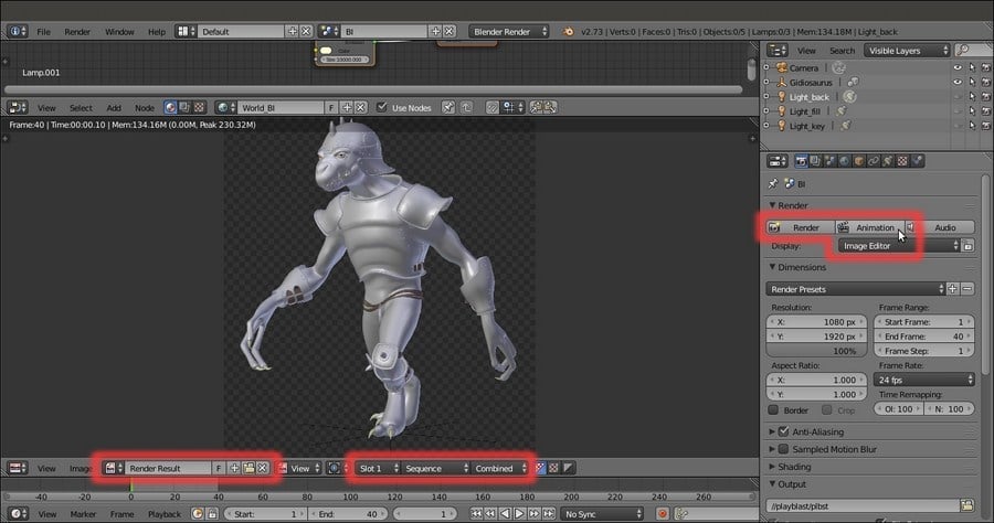
The Render Result window
Getting ready
Start Blender and load the Gidiosaurus_lighting.blend file.
- In the Outliner, select the Light_key lamp item and go to the Object Data window, under the Spot Shape subpanel, to disable the Show Cone item.
- Repeat the procedure for the Light_back and Light_fill lamps, then disable their visibility in the 3D viewport by clicking on the respective eye icon.
- Disable the visibility in the viewport for the Gidiosaurus_proxy item (the linked and proxified rig) also and/or disable the 11th scene layer.
- Save the file as
Gidiosaurus_playblast.blend.
Here are the steps to begin with the OpenGL rendering:
- Put the mouse pointer inside the 3D viewport and press the numpad 0 key to go in Camera view; press the Z key to go in Solid viewport shading mode, then scroll the mouse wheel to zoom the Camera view inside the window:
The Camera view in Solid viewport shading mode
- Go to the Render window and to the Dimensions subpanel; check for the X and Y sizes of the rendering under Resolution, specified in pixels, and move the Percentage scale for render resolution slider, usually set to 50%, to 100%.
- Go down to the Output subpanel and click on the folder icon button to the end of the path slot; browse to the location you want to save your rendering, then type in the first line of the path to the folder you want to create at that location, followed by the slash (
/) and press Enter. - A pop-up will ask you to confirm the creation of the new directory; confirm and then type a generic frame name in the second line, go to the left side vertical bar to be sure that the bottom Relative Path item is enabled and finally click on the Accept button at the top left of the screen.
I used playblast for the folder and plbst for the frame name respectively.
The new directory and the rendered frames name
- Save the file, then go to the Camera view toolbar and click on the last ciak icon button to the left to start the OpenGL playblast:
The two buttons to start the OpenGL rendering (for a still to the left, for the animation to the right)
In our example, the OpenGL playblast rendered single .png images with an alpha background because, as you can see in the Render window visible in the previous screenshot, these are the settings of the Output subpanel. Be aware that the resolution, the format and the path where the playblast frames are saved, always depend on the settings in the Render window, the same settings that will be used for the final real rendering (but of course the resolution of the playblast can be easily and temporarily be made smaller with the slider of the percentage scale).
Once we have rendered all the frames, we can use an external player to see them in sequence (in Ubuntu, I use the free player DJV Imaging, http://djv.sourceforge.net) or, just quickly build a movie through the Blender Sequencer:
- Go to the Screen datablock button on the top main header and click it to switch to the Video Editing screen:
Switching to the Video Editing screen layout
- Put the mouse pointer in the Video Sequence Editor window at the bottom and press Shift + A; from the pop-up menu select the Image item (Add an image or image sequence to the sequencer), then browse to the
playblastfolder location, click on it and once inside, press the A key to select all the contained frames, then press Enter to confirm. The frames are added to the Video Sequence Editor window as a single strip and the current frame appears in the preview window:Loading the rendered frames in the Video Sequence Editor
- Go back to the Default screen and to the Render window under the main Properties panel. In the Output subpanel, where you can change the path to save the movie in a different location (or also leave it as it is), click on the File Format button to select a Movie format, for example, AVI JPEG. Choose BW or RGB and the Quality compression ratio (but the default 90% is usually OK); then go to the Post Processing subpanel and ensure that the Sequencer item is enabled:
The Output and the Post Processing subpanels inside the Render window
- Go to the top of the Render window and click on the Animation button; remember that Blender uses two different buttons to start the rendering of a still image or of an animation, both for the final rendering and for the 3D viewport toolbar OpenGL preview we have seen in the How to do it… section.
The rendering starts and the Sequencer processes all the .png images outputted by the playblast, transforming them into a single compressed .avi movie then saved in the same directory as the frames.
The process is visible in the UV/Image Editor window that replaced the Camera view, indicated in the toolbar by the Render Result label on the image datablock to the left (because the Image Editor item is the one selected in the Display slot under the Render subpanel) and by the Sequence label visible in the Layer slot to the right:
The Render Result window
How to do it…
Here are the steps to begin with the OpenGL rendering:
- Put the mouse pointer inside the 3D viewport and press the numpad 0 key to go in Camera view; press the Z key to go in Solid viewport shading mode, then scroll the mouse wheel to zoom the Camera view inside the window:
The Camera view in Solid viewport shading mode
- Go to the Render window and to the Dimensions subpanel; check for the X and Y sizes of the rendering under Resolution, specified in pixels, and move the Percentage scale for render resolution slider, usually set to 50%, to 100%.
- Go down to the Output subpanel and click on the folder icon button to the end of the path slot; browse to the location you want to save your rendering, then type in the first line of the path to the folder you want to create at that location, followed by the slash (
/) and press Enter. - A pop-up will ask you to confirm the creation of the new directory; confirm and then type a generic frame name in the second line, go to the left side vertical bar to be sure that the bottom Relative Path item is enabled and finally click on the Accept button at the top left of the screen.
I used playblast for the folder and plbst for the frame name respectively.
The new directory and the rendered frames name
- Save the file, then go to the Camera view toolbar and click on the last ciak icon button to the left to start the OpenGL playblast:
The two buttons to start the OpenGL rendering (for a still to the left, for the animation to the right)
In our example, the OpenGL playblast rendered single .png images with an alpha background because, as you can see in the Render window visible in the previous screenshot, these are the settings of the Output subpanel. Be aware that the resolution, the format and the path where the playblast frames are saved, always depend on the settings in the Render window, the same settings that will be used for the final real rendering (but of course the resolution of the playblast can be easily and temporarily be made smaller with the slider of the percentage scale).
Once we have rendered all the frames, we can use an external player to see them in sequence (in Ubuntu, I use the free player DJV Imaging, http://djv.sourceforge.net) or, just quickly build a movie through the Blender Sequencer:
- Go to the Screen datablock button on the top main header and click it to switch to the Video Editing screen:
Switching to the Video Editing screen layout
- Put the mouse pointer in the Video Sequence Editor window at the bottom and press Shift + A; from the pop-up menu select the Image item (Add an image or image sequence to the sequencer), then browse to the
playblastfolder location, click on it and once inside, press the A key to select all the contained frames, then press Enter to confirm. The frames are added to the Video Sequence Editor window as a single strip and the current frame appears in the preview window:Loading the rendered frames in the Video Sequence Editor
- Go back to the Default screen and to the Render window under the main Properties panel. In the Output subpanel, where you can change the path to save the movie in a different location (or also leave it as it is), click on the File Format button to select a Movie format, for example, AVI JPEG. Choose BW or RGB and the Quality compression ratio (but the default 90% is usually OK); then go to the Post Processing subpanel and ensure that the Sequencer item is enabled:
The Output and the Post Processing subpanels inside the Render window
- Go to the top of the Render window and click on the Animation button; remember that Blender uses two different buttons to start the rendering of a still image or of an animation, both for the final rendering and for the 3D viewport toolbar OpenGL preview we have seen in the How to do it… section.
The rendering starts and the Sequencer processes all the .png images outputted by the playblast, transforming them into a single compressed .avi movie then saved in the same directory as the frames.
The process is visible in the UV/Image Editor window that replaced the Camera view, indicated in the toolbar by the Render Result label on the image datablock to the left (because the Image Editor item is the one selected in the Display slot under the Render subpanel) and by the Sequence label visible in the Layer slot to the right:
The Render Result window
How it works…
In our example, the OpenGL playblast rendered single .png images with an alpha background because, as you can see in the Render window visible in the previous screenshot, these are the settings of the Output subpanel. Be aware that the resolution, the format and the path where the playblast frames are saved, always depend on the settings in the Render window, the same settings that will be used for the final real rendering (but of course the resolution of the playblast can be easily and temporarily be made smaller with the slider of the percentage scale).
Once we have rendered all the frames, we can use an external player to see them in sequence (in Ubuntu, I use the free player DJV Imaging, http://djv.sourceforge.net) or, just quickly build a movie through the Blender Sequencer:
- Go to the Screen datablock button on the top main header and click it to switch to the Video Editing screen:
Switching to the Video Editing screen layout
- Put the mouse pointer in the Video Sequence Editor window at the bottom and press Shift + A; from the pop-up menu select the Image item (Add an image or image sequence to the sequencer), then browse to the
playblastfolder location, click on it and once inside, press the A key to select all the contained frames, then press Enter to confirm. The frames are added to the Video Sequence Editor window as a single strip and the current frame appears in the preview window:Loading the rendered frames in the Video Sequence Editor
- Go back to the Default screen and to the Render window under the main Properties panel. In the Output subpanel, where you can change the path to save the movie in a different location (or also leave it as it is), click on the File Format button to select a Movie format, for example, AVI JPEG. Choose BW or RGB and the Quality compression ratio (but the default 90% is usually OK); then go to the Post Processing subpanel and ensure that the Sequencer item is enabled:
The Output and the Post Processing subpanels inside the Render window
- Go to the top of the Render window and click on the Animation button; remember that Blender uses two different buttons to start the rendering of a still image or of an animation, both for the final rendering and for the 3D viewport toolbar OpenGL preview we have seen in the How to do it… section.
The rendering starts and the Sequencer processes all the .png images outputted by the playblast, transforming them into a single compressed .avi movie then saved in the same directory as the frames.
The process is visible in the UV/Image Editor window that replaced the Camera view, indicated in the toolbar by the Render Result label on the image datablock to the left (because the Image Editor item is the one selected in the Display slot under the Render subpanel) and by the Sequence label visible in the Layer slot to the right:
The Render Result window
There's more…
Once we have rendered all the frames, we can use an external player to see them in sequence (in Ubuntu, I use the free player DJV Imaging, http://djv.sourceforge.net) or, just quickly build a movie through the Blender Sequencer:
- Go to the Screen datablock button on the top main header and click it to switch to the Video Editing screen:
Switching to the Video Editing screen layout
- Put the mouse pointer in the Video Sequence Editor window at the bottom and press Shift + A; from the pop-up menu select the Image item (Add an image or image sequence to the sequencer), then browse to the
playblastfolder location, click on it and once inside, press the A key to select all the contained frames, then press Enter to confirm. The frames are added to the Video Sequence Editor window as a single strip and the current frame appears in the preview window:Loading the rendered frames in the Video Sequence Editor
- Go back to the Default screen and to the Render window under the main Properties panel. In the Output subpanel, where you can change the path to save the movie in a different location (or also leave it as it is), click on the File Format button to select a Movie format, for example, AVI JPEG. Choose BW or RGB and the Quality compression ratio (but the default 90% is usually OK); then go to the Post Processing subpanel and ensure that the Sequencer item is enabled:
The Output and the Post Processing subpanels inside the Render window
- Go to the top of the Render window and click on the Animation button; remember that Blender uses two different buttons to start the rendering of a still image or of an animation, both for the final rendering and for the 3D viewport toolbar OpenGL preview we have seen in the How to do it… section.
The rendering starts and the Sequencer processes all the .png images outputted by the playblast, transforming them into a single compressed .avi movie then saved in the same directory as the frames.
The process is visible in the UV/Image Editor window that replaced the Camera view, indicated in the toolbar by the Render Result label on the image datablock to the left (because the Image Editor item is the one selected in the Display slot under the Render subpanel) and by the Sequence label visible in the Layer slot to the right:
The Render Result window
The Cycles Render engine can be very slow compared to Blender Internal; by the way, some of the rendering settings can be tweaked to make it work faster; the goal here is to avoid fireflies and noise, usually due to low samples and a light source that is too bright.

Rendered previews of an example scene, showing a cube on a plane with and without noise and fireflies
Start Blender and load the Gidiosaurus_playblast.blend file.
- Click on the Scene datablock button in the top main header to switch from BI to Cycles.
- Go to the Outliner and enable the visibility of the Light_key lamp in the viewport by clicking on the grayed eye icon.
- Put the mouse pointer inside the Camera view and press Shift + B to draw a box around the character's head, then zoom to it.
- Save the file as
Gidiosaurus_render.blendand press Shift + Z to start the Rendered preview.
If you have a capable graphic card supporting GPU (go to the last See also section for the link to a list of supported GPU graphic cards for Cycles), the next thing to do is:
- Call the User Preferences panel (Ctrl + Alt +U) and go to the System tab; on the bottom left there is the Compute Device item and the slot you can click on to select the device for the rendering: if you have a graphic card that supports this feature, set the GPU instead of the default CPU, and to make this permanent, click on the Save User Settings button, or press Ctrl + U, and close the panel.
- Go to the Render window under the main Properties panel and, in the top Render subpanel it is now possible to select the GPU item as a rendering device, but only if your graphic card supports CUDA.
This will boost your rendering speed several times, making it possible to significantly increase the rendering samples in the Sampling subpanel to reduce or even avoid the noise and keep good rendering times. Using the GPU, it's also possible to increase the size of the X and Y Tiles in the Performance subpanel (two or three times the default size is 64).
But, not everyone has a GPU graphic card yet, and there are also cases where you have to mandatorily use the CPU instead (for example, for very big scenes with a lot of geometry that doesn't fit inside the somewhat limited RAM of a graphic card).
In such cases, there are things you can do to try to obtain faster and better quality render results:
- Select the Light_key lamp and in the Node Editor window add a Light_Falloff node (Shift + A | Color | Light Falloff); connect its Linear output to the Strength input socket of the Emission node, set the Strength to 1000.000 and the Smooth value to 1.000.
- Click on the color box of the Emission node and change the color to R 0.800, G 0.800, B 0.650.
- Go to the Render window and in the Sampling subpanel set the Samples to 200 or a higher value both for Render and Preview, to reduce the noise as much as possible.
- Set the Clamp Direct and the Clamp Indirect values to 3.00 or 4.00 or even higher (they are set to 0.00 by default); when possible, it is better to leave the Clamp Direct item at 0.00 or use values higher then 2.00, otherwise you could get weird effects in the texturing.
- In the Light Path subpanel, disable both the Reflective Caustics and the Refractive Caustics items (unless you really need to have caustics in your render) and set the Filter Glossy value to 4.00 – 6.00.
- In some cases, it won't be possible to totally eliminate the noise or the fireflies; but, because we are going to render an animation, that is several frames in sequence, at least we can make the noise less noticeable and more natural looking: go back to the Sampling subpanel and click on the Seed slot to type
#frame. This creates an automated driver that takes the seed value from the current frame number, in order to have different noise at every frame.
The Light Falloff node for the Lamps, the Seed driver for the noise, the Caustics items and the Filter Glossy value
- http://www.blender.org/manual/render/cycles/reducing_noise.html
- http://www.blender.org/manual/render/cycles/settings/index.html
- http://www.blender.org/manual/render/cycles/gpu_rendering.html
- http://www.blender.org/manual/render/workflows/animations.html
- http://www.blender.org/manual/render/blender_render/performance.html
- A list of supported GPU graphic cards for Cycles can be found at https://developer.nvidia.com/cuda-gpus
Getting ready
Start Blender and load the Gidiosaurus_playblast.blend file.
- Click on the Scene datablock button in the top main header to switch from BI to Cycles.
- Go to the Outliner and enable the visibility of the Light_key lamp in the viewport by clicking on the grayed eye icon.
- Put the mouse pointer inside the Camera view and press Shift + B to draw a box around the character's head, then zoom to it.
- Save the file as
Gidiosaurus_render.blendand press Shift + Z to start the Rendered preview.
If you have a capable graphic card supporting GPU (go to the last See also section for the link to a list of supported GPU graphic cards for Cycles), the next thing to do is:
- Call the User Preferences panel (Ctrl + Alt +U) and go to the System tab; on the bottom left there is the Compute Device item and the slot you can click on to select the device for the rendering: if you have a graphic card that supports this feature, set the GPU instead of the default CPU, and to make this permanent, click on the Save User Settings button, or press Ctrl + U, and close the panel.
- Go to the Render window under the main Properties panel and, in the top Render subpanel it is now possible to select the GPU item as a rendering device, but only if your graphic card supports CUDA.
This will boost your rendering speed several times, making it possible to significantly increase the rendering samples in the Sampling subpanel to reduce or even avoid the noise and keep good rendering times. Using the GPU, it's also possible to increase the size of the X and Y Tiles in the Performance subpanel (two or three times the default size is 64).
But, not everyone has a GPU graphic card yet, and there are also cases where you have to mandatorily use the CPU instead (for example, for very big scenes with a lot of geometry that doesn't fit inside the somewhat limited RAM of a graphic card).
In such cases, there are things you can do to try to obtain faster and better quality render results:
- Select the Light_key lamp and in the Node Editor window add a Light_Falloff node (Shift + A | Color | Light Falloff); connect its Linear output to the Strength input socket of the Emission node, set the Strength to 1000.000 and the Smooth value to 1.000.
- Click on the color box of the Emission node and change the color to R 0.800, G 0.800, B 0.650.
- Go to the Render window and in the Sampling subpanel set the Samples to 200 or a higher value both for Render and Preview, to reduce the noise as much as possible.
- Set the Clamp Direct and the Clamp Indirect values to 3.00 or 4.00 or even higher (they are set to 0.00 by default); when possible, it is better to leave the Clamp Direct item at 0.00 or use values higher then 2.00, otherwise you could get weird effects in the texturing.
- In the Light Path subpanel, disable both the Reflective Caustics and the Refractive Caustics items (unless you really need to have caustics in your render) and set the Filter Glossy value to 4.00 – 6.00.
- In some cases, it won't be possible to totally eliminate the noise or the fireflies; but, because we are going to render an animation, that is several frames in sequence, at least we can make the noise less noticeable and more natural looking: go back to the Sampling subpanel and click on the Seed slot to type
#frame. This creates an automated driver that takes the seed value from the current frame number, in order to have different noise at every frame.The Light Falloff node for the Lamps, the Seed driver for the noise, the Caustics items and the Filter Glossy value
- http://www.blender.org/manual/render/cycles/reducing_noise.html
- http://www.blender.org/manual/render/cycles/settings/index.html
- http://www.blender.org/manual/render/cycles/gpu_rendering.html
- http://www.blender.org/manual/render/workflows/animations.html
- http://www.blender.org/manual/render/blender_render/performance.html
- A list of supported GPU graphic cards for Cycles can be found at https://developer.nvidia.com/cuda-gpus
How to do it…
If you have a capable graphic card supporting GPU (go to the last See also section for the link to a list of supported GPU graphic cards for Cycles), the next thing to do is:
- Call the User Preferences panel (Ctrl + Alt +U) and go to the System tab; on the bottom left there is the Compute Device item and the slot you can click on to select the device for the rendering: if you have a graphic card that supports this feature, set the GPU instead of the default CPU, and to make this permanent, click on the Save User Settings button, or press Ctrl + U, and close the panel.
- Go to the Render window under the main Properties panel and, in the top Render subpanel it is now possible to select the GPU item as a rendering device, but only if your graphic card supports CUDA.
This will boost your rendering speed several times, making it possible to significantly increase the rendering samples in the Sampling subpanel to reduce or even avoid the noise and keep good rendering times. Using the GPU, it's also possible to increase the size of the X and Y Tiles in the Performance subpanel (two or three times the default size is 64).
But, not everyone has a GPU graphic card yet, and there are also cases where you have to mandatorily use the CPU instead (for example, for very big scenes with a lot of geometry that doesn't fit inside the somewhat limited RAM of a graphic card).
In such cases, there are things you can do to try to obtain faster and better quality render results:
- Select the Light_key lamp and in the Node Editor window add a Light_Falloff node (Shift + A | Color | Light Falloff); connect its Linear output to the Strength input socket of the Emission node, set the Strength to 1000.000 and the Smooth value to 1.000.
- Click on the color box of the Emission node and change the color to R 0.800, G 0.800, B 0.650.
- Go to the Render window and in the Sampling subpanel set the Samples to 200 or a higher value both for Render and Preview, to reduce the noise as much as possible.
- Set the Clamp Direct and the Clamp Indirect values to 3.00 or 4.00 or even higher (they are set to 0.00 by default); when possible, it is better to leave the Clamp Direct item at 0.00 or use values higher then 2.00, otherwise you could get weird effects in the texturing.
- In the Light Path subpanel, disable both the Reflective Caustics and the Refractive Caustics items (unless you really need to have caustics in your render) and set the Filter Glossy value to 4.00 – 6.00.
- In some cases, it won't be possible to totally eliminate the noise or the fireflies; but, because we are going to render an animation, that is several frames in sequence, at least we can make the noise less noticeable and more natural looking: go back to the Sampling subpanel and click on the Seed slot to type
#frame. This creates an automated driver that takes the seed value from the current frame number, in order to have different noise at every frame.The Light Falloff node for the Lamps, the Seed driver for the noise, the Caustics items and the Filter Glossy value
- http://www.blender.org/manual/render/cycles/reducing_noise.html
- http://www.blender.org/manual/render/cycles/settings/index.html
- http://www.blender.org/manual/render/cycles/gpu_rendering.html
- http://www.blender.org/manual/render/workflows/animations.html
- http://www.blender.org/manual/render/blender_render/performance.html
- A list of supported GPU graphic cards for Cycles can be found at https://developer.nvidia.com/cuda-gpus
See also
- http://www.blender.org/manual/render/cycles/reducing_noise.html
- http://www.blender.org/manual/render/cycles/settings/index.html
- http://www.blender.org/manual/render/cycles/gpu_rendering.html
- http://www.blender.org/manual/render/workflows/animations.html
- http://www.blender.org/manual/render/blender_render/performance.html
- A list of supported GPU graphic cards for Cycles can be found at https://developer.nvidia.com/cuda-gpus
We have seen that the rendering in the Cycles Render engine is quite slow but of very good quality, while the scanline Blender Render engine is faster but with a lower quality.
Thanks to the Blender integrated Compositor and to the render layers, it is possible to mix separated and different passes of both the renderers, obtaining a compromise between quality and speed, for example, by over-imposing the glossy pass obtained in Cycles on the diffuse pass obtained in BI, and so on.
To mix different passes obtained from the two render engines, we must first apply some modification to the materials of the library file:
- Start Blender and load the
Gidiosaurus_shaders_Blender_Internal.blendfile, which is the file we used as library for the proxified character and the walkcycle action. - In the Outliner select the Gidiosaurus_lowres item, be sure to be in the BI scene and go to the Material window; select the first material slot, that is the
Material_skin_U0V0slot, and in the Node Editor window select the SPEC material node:
The SPEC node material for Blender Internal
- Go to the Texture window and click on the Enable/Disable each texture checkbox at the right side of the env_refl_skin texture slot to disable it:

The disabled "env_refl_skin" texture slot
- Go back to the Node Editor window and select the COL node (this seems to be important, because of a bug in the Blender Internal working method with linked material nodes and the despgraph that doesn't update the materials and, therefore, doesn't render the diffuse color correctly).
- Select the second
Material_skin_U1V0slot, go to the Node Editor, select the SPEC material node, disable theenv_refl_skintexture slot, select the COL material node, then go to the thirdMaterial_skin_U2V0slot, and so on: repeat for all the materials of the Gidiosaurus and of the Armor objects (for the Armor disable theenv_refl_armorslots on both the SPEC1 and SPEC2 material nodes; Eyes and Corneas have the real ray-tracing mirror enabled and don't need any textures disabled).Remember to leave the COL material nodes as the selected ones in the Node Editor window, or the diffuse color won't show in the rendering.
- Go to the Object window and, in the Relations subpanel, assign a different Pass Index to the objects: assign 1 to the Gidiosaurus_lowres object, 2 to the Armor object, 3 to the Eyes, and 4 to the Corneas.

The Pass Index slot
- Save the file as
Gidiosaurus_shaders_library.blend.Now, because up to this point we have used the
Gidiosaurus_shaders_Blender_Internal.blendfile as library source, we must now substitute the file to be rendered the path to the new library source: - Open the
Gidiosaurus_render.blendfile and go to the Outliner window: click on the Type of information to display button at the top to switch from Visible Layers to Blender File; expand the panel to find the //Gidiosaurus_shaders_Blender_Internal.blend item at the bottom:
The library path in the Outliner
- Double left-click on the item and rename it as //Gidiosaurus_shaders_library.blend, then press Enter to confirm and save the file:

The modified library path
- Press Ctrl + O | Enter to re-load the file: now all the assets should be linked from the new library file.
- Save the file as
Gidiosaurus_compositing.blend.
At this point we must prepare the passes for the two scenes that will be used later, as elements to be mixed through a third new compositing scene:
- Click on the + icon button to the right side of the Scene datablock button in the main top header and, in the New Scene pop-up menu, select the New item: this creates a new empty scene; rename it comp.
- Click on the Screen datablock button to the left and switch to the Compositing screen, then click again on the Scene datablock button and re-select the newly created comp scene.
- Click again on the Screen datablock button and go back to the Default screen; go to the Scene datablock button and select either the BI or the Cycles scene.
- From now on, it's enough to select the Compositing layout in the Screen datablock button to switch automatically to the comp scene, and the Default layout to go to the BI or the Cycles scene (depending on the last one selected).
- Go to the Default screen and, if not already loaded, load the BI scene; in the main Properties panel, go to the Render Layers window (the second icon button from the left in the Type of active data to display and edit windows row).
- Double click on the RenderLayer name in the first slot at the top of the subpanel to rename it as BI. Go down to the Passes subpanel, disable the Z pass item and enable Object Index; then go to the second column and enable the Shadow pass but then also click on the Exclude shadow pass from combined button to its extreme right side: do the same also for the Emit, the AO and the Indirect passes.

The Passes setting for the Blender Render scene
- Click again on the Scene datablock button in the top main header and switch to the Cycles scene.
- Double click on the RenderLayer name in the first slot at the top of the subpanel to rename it as Cycles, then disable the Combined and the Z passes, leave the already enabled Shadow pass as it is and enable also the Glossy Direct, Indirect and Color passes:

The Passes setting for the Cycles Render scene
- Now click on the Screen datablock button and switch to the Compositing screen.
- In the Node Editor window toolbar, go to the Node tree type to display and edit row, click on the Compositing nodes button (the middle one) and then enable the Use Nodes checkbox:

The Compositing nodes button
Two compositing nodes are automatically added in the Node Editor window: a RenderLayers node connected to a Composite node.
- Click on the double arrows to the side of the Scene datablock on the RenderLayers node to switch from the comp scene to the BI scene, and, if necessary, in the bottom Layer button, select the name of the respective render layer (that we labeled as BI again; it shouldn't be necessary to select it, by the way, because it's the only render layer in the scene).

The render layer selector in the RenderLayers node and the output sockets to the Composite node
- Press Shift + D to duplicate the RenderLayers node and repeat the procedure in the duplicated one, this time selecting the Cycles scene datablock and render layer:

The duplicated RenderLayers node
- Put the mouse pointer inside the Node Editor window and press Shift + A to add a Viewer node (Shift + A | Output | Viewer); connect the Image output of the BI RenderLayers node also to the Image input socket of the Viewer node.
- Move down and switch the 3D View window with another UV/Image Editor window.
- In the left image editor window, click on the double arrows to the left of the image datablock (Browse Image to be linked) and from the pop-up menu select the Viewer Node item.
- In the right image editor window, instead, select the Render Result item.

The Viewer node and the Viewer Node and Render Result windows
- At this point, press F12 or click on the Render button inside the main Properties panel to start the rendering.
When the rendering is done, only the BI render is visible in the two bottom editor windows, because at the moment it's the only RenderLayers node connected to the Viewer and to the Composite nodes.
- Connect the Glossy Direct output of the Cycles RenderLayers node to the Image input socket of the Viewer node to see the single specularity pass in the left UV/Image Editor.

The Glossy Direct pass visualized in the Viewer Node window
In fact, we could also add more than one Viewer node to the Node Editor window and use them to visualize the different passes of RenderLayers, by connecting each pass output to each Viewer node; the last selected Viewer node will be the one visualized in the Viewer Node bottom window.
- Enable the Auto Render item at the extreme right side on the Node Editor window toolbar, add a Mix node (Shift + A | Color | Mix) and paste it between the Image output of the BI RenderLayers node and the Image input socket of the Composite node; change the Blend Type to Add and then connect the Glossy Direct output of the Cycles RenderLayers node to its second Image input socket. Set the Fac value to 0.050 and label it as Add_GLOSSY_01.
- If you want, also connect the output of the Add_GLOSSY_01 node to the Viewer node.

The Glossy pass, rendered in Cycles, added to the Image pass rendered in Blender Internal; note that now the armor looks too lightened
- Press Shift + D to duplicate the Add_GLOSSY_01 node, label it as Add_GLOSSY_02 and paste it between the Add_GLOSSY_01 and the Composite nodes; connect the Glossy_Indirect output of the Cycles RenderLayers node to the second Image input socket of the Add_GLOSSY_02 node.
- Press Shift + D to duplicate the Add_GLOSSY_01 node again, label it as Mul_GLOSSY, change the Blend Type to Multiply and set the Fac value back to 1.000; connect the output of the Add_GLOSSY_02 node to its first Image input socket and the Glossy_Direct output of the Cycles RenderLayers node to its second Image input socket. Connect the output of the Mul_GLOSSY node to the Composite node.
- Add an ID Mask node (Shift + A | Converter | ID Mask), set the Index value to 2 and connect the IndexOB output of the BI RenderLayers node to the ID value input socket, then connect the Alpha output to the Fac input socket of the Mul_GLOSSY node; enable the Anti-Aliasing item.
- For the moment, disconnect the Viewer node.

The IndexOB output used as a mask for the addition of the Glossy pass only on the character's skin
- Press Shift + D to duplicate a new Mix node, label it as Mix_GLOSSY and set the Blend Type to Mix and the Fac value to 0.900; connect the output of the Add_GLOSSY_02 node to the first Image input socket and the output of the Mul_GLOSSY node to the second Image input socket.
- Press Shift + D to duplicate another Mix node, label it as Color_GLOSSY and set the Blend Type to Color and the Fac to 0.050; connect the output of the Mix_GLOSSY node to the first Image input socket and the Glossy_color output of the Cycles RenderLayers node to the second Image input socket:

Adding more compositing nodes to re-build the separately rendered Glossy passes
- Add a new Mix node (Shift + A | Color | Mix) right after the Color_GLOSSY one, label it as Mul_AO, set the Blend Type to Multiply and connect the AO output of the BI RenderLayers node to the second Image input socket; set the Fac to 0.500.
- Add a new Mix node (Shift + A | Color | Mix), label it as SHADOWS, change the Blend Type to Multiply and set the Fac value to 1.000; connect the Shadow output of the BI RenderLayers node to its first Image input socket and the Shadow output of the Cycles RenderLayers node to the second Image input socket.
- Press Shift + D to duplicate the Mul_AO node and label it as Mul_SHADOWS; paste it right behind the Mul_AO node and set the Fac value slider to 1.000.
- Connect the output of the SHADOWS node to the second Image input socket of the Mul_SHADOWS node.
- Add a new Mix node (Shift + A | Color | Mix), label it as Color_SHADOWS and paste it right behind the SHADOWS node; set the Blend Type to Add, the Fac to 0.500 and enable the Clamp item: set the color of the second Image socket to R 0.640, G 0.780, B 1.000.

Multiplying and coloring the shadow pass
- Add a new Mix node (Shift + A | Color | Mix) right behind the Mul_SHADOWS one, label it as Add_INDIRECT; set the Blend Type to Add, the Fac to 0.300 and connect the Indirect output of the BI RenderLayers to the second Image input socket.
- Repeat the previous step but label the node as Add EMIT, set the Fac value to 1.000 and connect the Emit output of the BI RenderLayers node to the second Image input socket.
- Add one more Mix node (Shift + A | Color | Mix), label it as Col_EMIT, set the Blend Type to Multiply and paste it behind the Add_EMIT node; set the color of the second Image socket to R 1.000, G 0.542, B 0.073.
- Add a new ID Mask node (Shift + A | Converter | ID Mask), connect the IndexOB output of the BI RenderLayers node to the ID value socket, set the Index value to 3 and connect its Alpha output to the Fac input socket of the Col_EMIT node.

Coloring and adding the eyes
- Connect the output of the Col_EMIT also to the Image input socket of the Viewer node:

The completed compositing network
- Save the file.
In the Getting ready section:
- From step 2 to step 5 we disabled the env_refl_skin and the env_refl_armor texture slots in all the material nodes of the BI shaders; in fact, because we are going to add the Cycles reflection on the BI diffuse, we don't need to fake the environment reflection on the character and on the armor surfaces anymore.
- In step 6 we assigned a different Index Pass number to each one of the objects; this is useful to later separate the objects in the Compositor for particular effects (in our case we only needed the armor Index Pass number, but it's a good habit to give index passes to all the objects for any eventuality).
- At step 7 we saved the file with a new name, and at steps 8 and 9 we changed, in the file to be rendered, the path to the new library file.
In the How to do it… section:
- From step 1 to step 3 we added a new empty scene, comp, to the blend file, linked to the Compositing screen layout and to be used for the compositing.
- In fact, in the comp scene, all the compositing nodes are connected together so as to recreate the best possible rendering look of the Gidiosaurus, using the different passes from the different BI and Cycles scenes through the render layers.
- From step 4 to step 7 we enabled the required passes in the Render layers windows of both the BI and Cycles scenes; note that basically we set an almost complete only-diffuse render in Blender Internal (besides the Indirect, Ambient Occlusion and Emit passes, subtracted from the total render and separately outputted), while we set the Glossy passes in the Cycles engine.
- From step 8 to step 15 we set up the RenderLayers nodes, the Viewer and the Composite nodes.
The RenderLayers node outputs the rendering of a particular scene also delivering the enabled passes for that scene, through the Render Layer setup.
The Compositing node is the mandatory final output node and must always be connected as the last step of the compositing chain.
The Viewer node, instead, is optional but always used anyway to visualize the different steps of the compositing itself.
- At step 16 we started the rendering; Blender starts to render the BI and the Cycles scenes using the settings setup for each scene (and not the settings of the comp scene, which are true only for the compositing).
- From step 18 to step 34 we mixed the different passes together. Basically, we used the same approach that we have seen in the creation of the shaders, that is, by decomposing the final result into the different components; then, we obtained the diffuse from the Blender Internal engine because it's quite fast for that, and the glossy component from the Cycles render engine for the same reasons, and then we re-mixed them. The Subsurface Scattering pass is actually rendered together at the diffuse component in BI and is delivered through the Combined (Image) pass.
- The Mix_GLOSSY node added at step 24 is to tweak the strength of the multiplied Glossy Direct pass; we couldn't use the Fac value, in this case, because it was already used by the ID Mask output to isolate, thanks to the Object Index, the Armor from the rest of the render.
- With the Col_SHADOWS node at step 30 we obtained two goals: first, we set the dark intensity of the shadows to 0.500 and, second, we gave them a bluish coloration.
- The emission pass for the eyes has been added to the rendering through the same technique used to multiply the glossy only on the Armor, that is, by an ID Mask node and the Object Index.
Getting ready
To mix different passes obtained from the two render engines, we must first apply some modification to the materials of the library file:
- Start Blender and load the
Gidiosaurus_shaders_Blender_Internal.blendfile, which is the file we used as library for the proxified character and the walkcycle action. - In the Outliner select the Gidiosaurus_lowres item, be sure to be in the BI scene and go to the Material window; select the first material slot, that is the
Material_skin_U0V0slot, and in the Node Editor window select the SPEC material node:The SPEC node material for Blender Internal
- Go to the Texture window and click on the Enable/Disable each texture checkbox at the right side of the env_refl_skin texture slot to disable it:
The disabled "env_refl_skin" texture slot
- Go back to the Node Editor window and select the COL node (this seems to be important, because of a bug in the Blender Internal working method with linked material nodes and the despgraph that doesn't update the materials and, therefore, doesn't render the diffuse color correctly).
- Select the second
Material_skin_U1V0slot, go to the Node Editor, select the SPEC material node, disable theenv_refl_skintexture slot, select the COL material node, then go to the thirdMaterial_skin_U2V0slot, and so on: repeat for all the materials of the Gidiosaurus and of the Armor objects (for the Armor disable theenv_refl_armorslots on both the SPEC1 and SPEC2 material nodes; Eyes and Corneas have the real ray-tracing mirror enabled and don't need any textures disabled).Remember to leave the COL material nodes as the selected ones in the Node Editor window, or the diffuse color won't show in the rendering.
- Go to the Object window and, in the Relations subpanel, assign a different Pass Index to the objects: assign 1 to the Gidiosaurus_lowres object, 2 to the Armor object, 3 to the Eyes, and 4 to the Corneas.
The Pass Index slot
- Save the file as
Gidiosaurus_shaders_library.blend.Now, because up to this point we have used the
Gidiosaurus_shaders_Blender_Internal.blendfile as library source, we must now substitute the file to be rendered the path to the new library source: - Open the
Gidiosaurus_render.blendfile and go to the Outliner window: click on the Type of information to display button at the top to switch from Visible Layers to Blender File; expand the panel to find the //Gidiosaurus_shaders_Blender_Internal.blend item at the bottom:The library path in the Outliner
- Double left-click on the item and rename it as //Gidiosaurus_shaders_library.blend, then press Enter to confirm and save the file:
The modified library path
- Press Ctrl + O | Enter to re-load the file: now all the assets should be linked from the new library file.
- Save the file as
Gidiosaurus_compositing.blend.
At this point we must prepare the passes for the two scenes that will be used later, as elements to be mixed through a third new compositing scene:
- Click on the + icon button to the right side of the Scene datablock button in the main top header and, in the New Scene pop-up menu, select the New item: this creates a new empty scene; rename it comp.
- Click on the Screen datablock button to the left and switch to the Compositing screen, then click again on the Scene datablock button and re-select the newly created comp scene.
- Click again on the Screen datablock button and go back to the Default screen; go to the Scene datablock button and select either the BI or the Cycles scene.
- From now on, it's enough to select the Compositing layout in the Screen datablock button to switch automatically to the comp scene, and the Default layout to go to the BI or the Cycles scene (depending on the last one selected).
- Go to the Default screen and, if not already loaded, load the BI scene; in the main Properties panel, go to the Render Layers window (the second icon button from the left in the Type of active data to display and edit windows row).
- Double click on the RenderLayer name in the first slot at the top of the subpanel to rename it as BI. Go down to the Passes subpanel, disable the Z pass item and enable Object Index; then go to the second column and enable the Shadow pass but then also click on the Exclude shadow pass from combined button to its extreme right side: do the same also for the Emit, the AO and the Indirect passes.
The Passes setting for the Blender Render scene
- Click again on the Scene datablock button in the top main header and switch to the Cycles scene.
- Double click on the RenderLayer name in the first slot at the top of the subpanel to rename it as Cycles, then disable the Combined and the Z passes, leave the already enabled Shadow pass as it is and enable also the Glossy Direct, Indirect and Color passes:
The Passes setting for the Cycles Render scene
- Now click on the Screen datablock button and switch to the Compositing screen.
- In the Node Editor window toolbar, go to the Node tree type to display and edit row, click on the Compositing nodes button (the middle one) and then enable the Use Nodes checkbox:
The Compositing nodes button
Two compositing nodes are automatically added in the Node Editor window: a RenderLayers node connected to a Composite node.
- Click on the double arrows to the side of the Scene datablock on the RenderLayers node to switch from the comp scene to the BI scene, and, if necessary, in the bottom Layer button, select the name of the respective render layer (that we labeled as BI again; it shouldn't be necessary to select it, by the way, because it's the only render layer in the scene).
The render layer selector in the RenderLayers node and the output sockets to the Composite node
- Press Shift + D to duplicate the RenderLayers node and repeat the procedure in the duplicated one, this time selecting the Cycles scene datablock and render layer:
The duplicated RenderLayers node
- Put the mouse pointer inside the Node Editor window and press Shift + A to add a Viewer node (Shift + A | Output | Viewer); connect the Image output of the BI RenderLayers node also to the Image input socket of the Viewer node.
- Move down and switch the 3D View window with another UV/Image Editor window.
- In the left image editor window, click on the double arrows to the left of the image datablock (Browse Image to be linked) and from the pop-up menu select the Viewer Node item.
- In the right image editor window, instead, select the Render Result item.
The Viewer node and the Viewer Node and Render Result windows
- At this point, press F12 or click on the Render button inside the main Properties panel to start the rendering.
When the rendering is done, only the BI render is visible in the two bottom editor windows, because at the moment it's the only RenderLayers node connected to the Viewer and to the Composite nodes.
- Connect the Glossy Direct output of the Cycles RenderLayers node to the Image input socket of the Viewer node to see the single specularity pass in the left UV/Image Editor.
The Glossy Direct pass visualized in the Viewer Node window
In fact, we could also add more than one Viewer node to the Node Editor window and use them to visualize the different passes of RenderLayers, by connecting each pass output to each Viewer node; the last selected Viewer node will be the one visualized in the Viewer Node bottom window.
- Enable the Auto Render item at the extreme right side on the Node Editor window toolbar, add a Mix node (Shift + A | Color | Mix) and paste it between the Image output of the BI RenderLayers node and the Image input socket of the Composite node; change the Blend Type to Add and then connect the Glossy Direct output of the Cycles RenderLayers node to its second Image input socket. Set the Fac value to 0.050 and label it as Add_GLOSSY_01.
- If you want, also connect the output of the Add_GLOSSY_01 node to the Viewer node.
The Glossy pass, rendered in Cycles, added to the Image pass rendered in Blender Internal; note that now the armor looks too lightened
- Press Shift + D to duplicate the Add_GLOSSY_01 node, label it as Add_GLOSSY_02 and paste it between the Add_GLOSSY_01 and the Composite nodes; connect the Glossy_Indirect output of the Cycles RenderLayers node to the second Image input socket of the Add_GLOSSY_02 node.
- Press Shift + D to duplicate the Add_GLOSSY_01 node again, label it as Mul_GLOSSY, change the Blend Type to Multiply and set the Fac value back to 1.000; connect the output of the Add_GLOSSY_02 node to its first Image input socket and the Glossy_Direct output of the Cycles RenderLayers node to its second Image input socket. Connect the output of the Mul_GLOSSY node to the Composite node.
- Add an ID Mask node (Shift + A | Converter | ID Mask), set the Index value to 2 and connect the IndexOB output of the BI RenderLayers node to the ID value input socket, then connect the Alpha output to the Fac input socket of the Mul_GLOSSY node; enable the Anti-Aliasing item.
- For the moment, disconnect the Viewer node.
The IndexOB output used as a mask for the addition of the Glossy pass only on the character's skin
- Press Shift + D to duplicate a new Mix node, label it as Mix_GLOSSY and set the Blend Type to Mix and the Fac value to 0.900; connect the output of the Add_GLOSSY_02 node to the first Image input socket and the output of the Mul_GLOSSY node to the second Image input socket.
- Press Shift + D to duplicate another Mix node, label it as Color_GLOSSY and set the Blend Type to Color and the Fac to 0.050; connect the output of the Mix_GLOSSY node to the first Image input socket and the Glossy_color output of the Cycles RenderLayers node to the second Image input socket:
Adding more compositing nodes to re-build the separately rendered Glossy passes
- Add a new Mix node (Shift + A | Color | Mix) right after the Color_GLOSSY one, label it as Mul_AO, set the Blend Type to Multiply and connect the AO output of the BI RenderLayers node to the second Image input socket; set the Fac to 0.500.
- Add a new Mix node (Shift + A | Color | Mix), label it as SHADOWS, change the Blend Type to Multiply and set the Fac value to 1.000; connect the Shadow output of the BI RenderLayers node to its first Image input socket and the Shadow output of the Cycles RenderLayers node to the second Image input socket.
- Press Shift + D to duplicate the Mul_AO node and label it as Mul_SHADOWS; paste it right behind the Mul_AO node and set the Fac value slider to 1.000.
- Connect the output of the SHADOWS node to the second Image input socket of the Mul_SHADOWS node.
- Add a new Mix node (Shift + A | Color | Mix), label it as Color_SHADOWS and paste it right behind the SHADOWS node; set the Blend Type to Add, the Fac to 0.500 and enable the Clamp item: set the color of the second Image socket to R 0.640, G 0.780, B 1.000.
Multiplying and coloring the shadow pass
- Add a new Mix node (Shift + A | Color | Mix) right behind the Mul_SHADOWS one, label it as Add_INDIRECT; set the Blend Type to Add, the Fac to 0.300 and connect the Indirect output of the BI RenderLayers to the second Image input socket.
- Repeat the previous step but label the node as Add EMIT, set the Fac value to 1.000 and connect the Emit output of the BI RenderLayers node to the second Image input socket.
- Add one more Mix node (Shift + A | Color | Mix), label it as Col_EMIT, set the Blend Type to Multiply and paste it behind the Add_EMIT node; set the color of the second Image socket to R 1.000, G 0.542, B 0.073.
- Add a new ID Mask node (Shift + A | Converter | ID Mask), connect the IndexOB output of the BI RenderLayers node to the ID value socket, set the Index value to 3 and connect its Alpha output to the Fac input socket of the Col_EMIT node.
Coloring and adding the eyes
- Connect the output of the Col_EMIT also to the Image input socket of the Viewer node:
The completed compositing network
- Save the file.
In the Getting ready section:
- From step 2 to step 5 we disabled the env_refl_skin and the env_refl_armor texture slots in all the material nodes of the BI shaders; in fact, because we are going to add the Cycles reflection on the BI diffuse, we don't need to fake the environment reflection on the character and on the armor surfaces anymore.
- In step 6 we assigned a different Index Pass number to each one of the objects; this is useful to later separate the objects in the Compositor for particular effects (in our case we only needed the armor Index Pass number, but it's a good habit to give index passes to all the objects for any eventuality).
- At step 7 we saved the file with a new name, and at steps 8 and 9 we changed, in the file to be rendered, the path to the new library file.
In the How to do it… section:
- From step 1 to step 3 we added a new empty scene, comp, to the blend file, linked to the Compositing screen layout and to be used for the compositing.
- In fact, in the comp scene, all the compositing nodes are connected together so as to recreate the best possible rendering look of the Gidiosaurus, using the different passes from the different BI and Cycles scenes through the render layers.
- From step 4 to step 7 we enabled the required passes in the Render layers windows of both the BI and Cycles scenes; note that basically we set an almost complete only-diffuse render in Blender Internal (besides the Indirect, Ambient Occlusion and Emit passes, subtracted from the total render and separately outputted), while we set the Glossy passes in the Cycles engine.
- From step 8 to step 15 we set up the RenderLayers nodes, the Viewer and the Composite nodes.
The RenderLayers node outputs the rendering of a particular scene also delivering the enabled passes for that scene, through the Render Layer setup.
The Compositing node is the mandatory final output node and must always be connected as the last step of the compositing chain.
The Viewer node, instead, is optional but always used anyway to visualize the different steps of the compositing itself.
- At step 16 we started the rendering; Blender starts to render the BI and the Cycles scenes using the settings setup for each scene (and not the settings of the comp scene, which are true only for the compositing).
- From step 18 to step 34 we mixed the different passes together. Basically, we used the same approach that we have seen in the creation of the shaders, that is, by decomposing the final result into the different components; then, we obtained the diffuse from the Blender Internal engine because it's quite fast for that, and the glossy component from the Cycles render engine for the same reasons, and then we re-mixed them. The Subsurface Scattering pass is actually rendered together at the diffuse component in BI and is delivered through the Combined (Image) pass.
- The Mix_GLOSSY node added at step 24 is to tweak the strength of the multiplied Glossy Direct pass; we couldn't use the Fac value, in this case, because it was already used by the ID Mask output to isolate, thanks to the Object Index, the Armor from the rest of the render.
- With the Col_SHADOWS node at step 30 we obtained two goals: first, we set the dark intensity of the shadows to 0.500 and, second, we gave them a bluish coloration.
- The emission pass for the eyes has been added to the rendering through the same technique used to multiply the glossy only on the Armor, that is, by an ID Mask node and the Object Index.
How to do it…
At this point we must prepare the passes for the two scenes that will be used later, as elements to be mixed through a third new compositing scene:
- Click on the + icon button to the right side of the Scene datablock button in the main top header and, in the New Scene pop-up menu, select the New item: this creates a new empty scene; rename it comp.
- Click on the Screen datablock button to the left and switch to the Compositing screen, then click again on the Scene datablock button and re-select the newly created comp scene.
- Click again on the Screen datablock button and go back to the Default screen; go to the Scene datablock button and select either the BI or the Cycles scene.
- From now on, it's enough to select the Compositing layout in the Screen datablock button to switch automatically to the comp scene, and the Default layout to go to the BI or the Cycles scene (depending on the last one selected).
- Go to the Default screen and, if not already loaded, load the BI scene; in the main Properties panel, go to the Render Layers window (the second icon button from the left in the Type of active data to display and edit windows row).
- Double click on the RenderLayer name in the first slot at the top of the subpanel to rename it as BI. Go down to the Passes subpanel, disable the Z pass item and enable Object Index; then go to the second column and enable the Shadow pass but then also click on the Exclude shadow pass from combined button to its extreme right side: do the same also for the Emit, the AO and the Indirect passes.
The Passes setting for the Blender Render scene
- Click again on the Scene datablock button in the top main header and switch to the Cycles scene.
- Double click on the RenderLayer name in the first slot at the top of the subpanel to rename it as Cycles, then disable the Combined and the Z passes, leave the already enabled Shadow pass as it is and enable also the Glossy Direct, Indirect and Color passes:
The Passes setting for the Cycles Render scene
- Now click on the Screen datablock button and switch to the Compositing screen.
- In the Node Editor window toolbar, go to the Node tree type to display and edit row, click on the Compositing nodes button (the middle one) and then enable the Use Nodes checkbox:
The Compositing nodes button
Two compositing nodes are automatically added in the Node Editor window: a RenderLayers node connected to a Composite node.
- Click on the double arrows to the side of the Scene datablock on the RenderLayers node to switch from the comp scene to the BI scene, and, if necessary, in the bottom Layer button, select the name of the respective render layer (that we labeled as BI again; it shouldn't be necessary to select it, by the way, because it's the only render layer in the scene).
The render layer selector in the RenderLayers node and the output sockets to the Composite node
- Press Shift + D to duplicate the RenderLayers node and repeat the procedure in the duplicated one, this time selecting the Cycles scene datablock and render layer:
The duplicated RenderLayers node
- Put the mouse pointer inside the Node Editor window and press Shift + A to add a Viewer node (Shift + A | Output | Viewer); connect the Image output of the BI RenderLayers node also to the Image input socket of the Viewer node.
- Move down and switch the 3D View window with another UV/Image Editor window.
- In the left image editor window, click on the double arrows to the left of the image datablock (Browse Image to be linked) and from the pop-up menu select the Viewer Node item.
- In the right image editor window, instead, select the Render Result item.
The Viewer node and the Viewer Node and Render Result windows
- At this point, press F12 or click on the Render button inside the main Properties panel to start the rendering.
When the rendering is done, only the BI render is visible in the two bottom editor windows, because at the moment it's the only RenderLayers node connected to the Viewer and to the Composite nodes.
- Connect the Glossy Direct output of the Cycles RenderLayers node to the Image input socket of the Viewer node to see the single specularity pass in the left UV/Image Editor.
The Glossy Direct pass visualized in the Viewer Node window
In fact, we could also add more than one Viewer node to the Node Editor window and use them to visualize the different passes of RenderLayers, by connecting each pass output to each Viewer node; the last selected Viewer node will be the one visualized in the Viewer Node bottom window.
- Enable the Auto Render item at the extreme right side on the Node Editor window toolbar, add a Mix node (Shift + A | Color | Mix) and paste it between the Image output of the BI RenderLayers node and the Image input socket of the Composite node; change the Blend Type to Add and then connect the Glossy Direct output of the Cycles RenderLayers node to its second Image input socket. Set the Fac value to 0.050 and label it as Add_GLOSSY_01.
- If you want, also connect the output of the Add_GLOSSY_01 node to the Viewer node.
The Glossy pass, rendered in Cycles, added to the Image pass rendered in Blender Internal; note that now the armor looks too lightened
- Press Shift + D to duplicate the Add_GLOSSY_01 node, label it as Add_GLOSSY_02 and paste it between the Add_GLOSSY_01 and the Composite nodes; connect the Glossy_Indirect output of the Cycles RenderLayers node to the second Image input socket of the Add_GLOSSY_02 node.
- Press Shift + D to duplicate the Add_GLOSSY_01 node again, label it as Mul_GLOSSY, change the Blend Type to Multiply and set the Fac value back to 1.000; connect the output of the Add_GLOSSY_02 node to its first Image input socket and the Glossy_Direct output of the Cycles RenderLayers node to its second Image input socket. Connect the output of the Mul_GLOSSY node to the Composite node.
- Add an ID Mask node (Shift + A | Converter | ID Mask), set the Index value to 2 and connect the IndexOB output of the BI RenderLayers node to the ID value input socket, then connect the Alpha output to the Fac input socket of the Mul_GLOSSY node; enable the Anti-Aliasing item.
- For the moment, disconnect the Viewer node.
The IndexOB output used as a mask for the addition of the Glossy pass only on the character's skin
- Press Shift + D to duplicate a new Mix node, label it as Mix_GLOSSY and set the Blend Type to Mix and the Fac value to 0.900; connect the output of the Add_GLOSSY_02 node to the first Image input socket and the output of the Mul_GLOSSY node to the second Image input socket.
- Press Shift + D to duplicate another Mix node, label it as Color_GLOSSY and set the Blend Type to Color and the Fac to 0.050; connect the output of the Mix_GLOSSY node to the first Image input socket and the Glossy_color output of the Cycles RenderLayers node to the second Image input socket:
Adding more compositing nodes to re-build the separately rendered Glossy passes
- Add a new Mix node (Shift + A | Color | Mix) right after the Color_GLOSSY one, label it as Mul_AO, set the Blend Type to Multiply and connect the AO output of the BI RenderLayers node to the second Image input socket; set the Fac to 0.500.
- Add a new Mix node (Shift + A | Color | Mix), label it as SHADOWS, change the Blend Type to Multiply and set the Fac value to 1.000; connect the Shadow output of the BI RenderLayers node to its first Image input socket and the Shadow output of the Cycles RenderLayers node to the second Image input socket.
- Press Shift + D to duplicate the Mul_AO node and label it as Mul_SHADOWS; paste it right behind the Mul_AO node and set the Fac value slider to 1.000.
- Connect the output of the SHADOWS node to the second Image input socket of the Mul_SHADOWS node.
- Add a new Mix node (Shift + A | Color | Mix), label it as Color_SHADOWS and paste it right behind the SHADOWS node; set the Blend Type to Add, the Fac to 0.500 and enable the Clamp item: set the color of the second Image socket to R 0.640, G 0.780, B 1.000.
Multiplying and coloring the shadow pass
- Add a new Mix node (Shift + A | Color | Mix) right behind the Mul_SHADOWS one, label it as Add_INDIRECT; set the Blend Type to Add, the Fac to 0.300 and connect the Indirect output of the BI RenderLayers to the second Image input socket.
- Repeat the previous step but label the node as Add EMIT, set the Fac value to 1.000 and connect the Emit output of the BI RenderLayers node to the second Image input socket.
- Add one more Mix node (Shift + A | Color | Mix), label it as Col_EMIT, set the Blend Type to Multiply and paste it behind the Add_EMIT node; set the color of the second Image socket to R 1.000, G 0.542, B 0.073.
- Add a new ID Mask node (Shift + A | Converter | ID Mask), connect the IndexOB output of the BI RenderLayers node to the ID value socket, set the Index value to 3 and connect its Alpha output to the Fac input socket of the Col_EMIT node.
Coloring and adding the eyes
- Connect the output of the Col_EMIT also to the Image input socket of the Viewer node:
The completed compositing network
- Save the file.
In the Getting ready section:
- From step 2 to step 5 we disabled the env_refl_skin and the env_refl_armor texture slots in all the material nodes of the BI shaders; in fact, because we are going to add the Cycles reflection on the BI diffuse, we don't need to fake the environment reflection on the character and on the armor surfaces anymore.
- In step 6 we assigned a different Index Pass number to each one of the objects; this is useful to later separate the objects in the Compositor for particular effects (in our case we only needed the armor Index Pass number, but it's a good habit to give index passes to all the objects for any eventuality).
- At step 7 we saved the file with a new name, and at steps 8 and 9 we changed, in the file to be rendered, the path to the new library file.
In the How to do it… section:
- From step 1 to step 3 we added a new empty scene, comp, to the blend file, linked to the Compositing screen layout and to be used for the compositing.
- In fact, in the comp scene, all the compositing nodes are connected together so as to recreate the best possible rendering look of the Gidiosaurus, using the different passes from the different BI and Cycles scenes through the render layers.
- From step 4 to step 7 we enabled the required passes in the Render layers windows of both the BI and Cycles scenes; note that basically we set an almost complete only-diffuse render in Blender Internal (besides the Indirect, Ambient Occlusion and Emit passes, subtracted from the total render and separately outputted), while we set the Glossy passes in the Cycles engine.
- From step 8 to step 15 we set up the RenderLayers nodes, the Viewer and the Composite nodes.
The RenderLayers node outputs the rendering of a particular scene also delivering the enabled passes for that scene, through the Render Layer setup.
The Compositing node is the mandatory final output node and must always be connected as the last step of the compositing chain.
The Viewer node, instead, is optional but always used anyway to visualize the different steps of the compositing itself.
- At step 16 we started the rendering; Blender starts to render the BI and the Cycles scenes using the settings setup for each scene (and not the settings of the comp scene, which are true only for the compositing).
- From step 18 to step 34 we mixed the different passes together. Basically, we used the same approach that we have seen in the creation of the shaders, that is, by decomposing the final result into the different components; then, we obtained the diffuse from the Blender Internal engine because it's quite fast for that, and the glossy component from the Cycles render engine for the same reasons, and then we re-mixed them. The Subsurface Scattering pass is actually rendered together at the diffuse component in BI and is delivered through the Combined (Image) pass.
- The Mix_GLOSSY node added at step 24 is to tweak the strength of the multiplied Glossy Direct pass; we couldn't use the Fac value, in this case, because it was already used by the ID Mask output to isolate, thanks to the Object Index, the Armor from the rest of the render.
- With the Col_SHADOWS node at step 30 we obtained two goals: first, we set the dark intensity of the shadows to 0.500 and, second, we gave them a bluish coloration.
- The emission pass for the eyes has been added to the rendering through the same technique used to multiply the glossy only on the Armor, that is, by an ID Mask node and the Object Index.
How it works…
In the Getting ready section:
- From step 2 to step 5 we disabled the env_refl_skin and the env_refl_armor texture slots in all the material nodes of the BI shaders; in fact, because we are going to add the Cycles reflection on the BI diffuse, we don't need to fake the environment reflection on the character and on the armor surfaces anymore.
- In step 6 we assigned a different Index Pass number to each one of the objects; this is useful to later separate the objects in the Compositor for particular effects (in our case we only needed the armor Index Pass number, but it's a good habit to give index passes to all the objects for any eventuality).
- At step 7 we saved the file with a new name, and at steps 8 and 9 we changed, in the file to be rendered, the path to the new library file.
In the How to do it… section:
- From step 1 to step 3 we added a new empty scene, comp, to the blend file, linked to the Compositing screen layout and to be used for the compositing.
- In fact, in the comp scene, all the compositing nodes are connected together so as to recreate the best possible rendering look of the Gidiosaurus, using the different passes from the different BI and Cycles scenes through the render layers.
- From step 4 to step 7 we enabled the required passes in the Render layers windows of both the BI and Cycles scenes; note that basically we set an almost complete only-diffuse render in Blender Internal (besides the Indirect, Ambient Occlusion and Emit passes, subtracted from the total render and separately outputted), while we set the Glossy passes in the Cycles engine.
- From step 8 to step 15 we set up the RenderLayers nodes, the Viewer and the Composite nodes.
The RenderLayers node outputs the rendering of a particular scene also delivering the enabled passes for that scene, through the Render Layer setup.
The Compositing node is the mandatory final output node and must always be connected as the last step of the compositing chain.
The Viewer node, instead, is optional but always used anyway to visualize the different steps of the compositing itself.
- At step 16 we started the rendering; Blender starts to render the BI and the Cycles scenes using the settings setup for each scene (and not the settings of the comp scene, which are true only for the compositing).
- From step 18 to step 34 we mixed the different passes together. Basically, we used the same approach that we have seen in the creation of the shaders, that is, by decomposing the final result into the different components; then, we obtained the diffuse from the Blender Internal engine because it's quite fast for that, and the glossy component from the Cycles render engine for the same reasons, and then we re-mixed them. The Subsurface Scattering pass is actually rendered together at the diffuse component in BI and is delivered through the Combined (Image) pass.
- The Mix_GLOSSY node added at step 24 is to tweak the strength of the multiplied Glossy Direct pass; we couldn't use the Fac value, in this case, because it was already used by the ID Mask output to isolate, thanks to the Object Index, the Armor from the rest of the render.
- With the Col_SHADOWS node at step 30 we obtained two goals: first, we set the dark intensity of the shadows to 0.500 and, second, we gave them a bluish coloration.
- The emission pass for the eyes has been added to the rendering through the same technique used to multiply the glossy only on the Armor, that is, by an ID Mask node and the Object Index.


