Cycles materials work in a totally different way than in Blender Internal.
In Blender Internal, you can build a material by choosing a diffuse and a specular shader from the Material window, by setting several surface options, and then by assigning textures (both procedurals or image maps as well) in the provided slots—all these steps make one complete material. After this, it's possible to combine two or more of these materials by a network of nodes, thereby obtaining a lot more flexibility in a shader's creation. But, the materials themselves are just the same you used to set through the Material window, that is, shaders made for a scan-line rendering engine as Blender Internal is, and their result is actually just an approximation of a simulated light absorption-reflection surface behavior.
In Cycles the approach is quite different: all the names of the closures describing surface properties have a Bidirectional Scattering Distribution Function (BSDF), which is a general mathematical function that describes the way in which the light is scattered by a surface in the real world. It's also the formula that a path tracer such as Cycles uses to calculate the rendering of an object in a virtual environment. Basically, light rays are shot from the camera, they bounce on the objects in the scene and keep on bouncing until they reach a light source or an "empty" background. For this reason, a pure path tracer such as Cycles can render in reasonable times an object set in an open environment, while instead the rendering times increase a lot for closed spaces. For example, furniture set inside a room, and this is just because the light rays can bounce on the floor, the ceiling, and the walls a good many times before reaching one or more light sources.
In short, the main difference between the two rendering engines is due to the fact that, while in Blender Internal the materials use all the traditional shader tricks of a scan-line rendering engine such as, for example, the simulated specular component, the Cycles rendering engine is a path tracer trying to mimic the real behavior of a surface as closely as possible as in real life. This is the reason why in Cycles we don't have, for example, the arbitrary Spec factor simulating the reflection point of the light on the surface, but a glossy shader actually mirroring the light source and the surrounding, to be mixed to the other components in different ratios and so behaving, in this respect, in a more correct way.
In any case, just for explanatory purposes, in this book I will still refer to the more or less blurred point of light created by the reflection of the light source on a mirroring glossy surface as Specularity.
Be aware that the rendering speed in Cycles depends on the device—CPU or GPU—you use to render your scenes. That is, basically you can decide to use the power of the CPU (default option) or the power of the graphic card processor, the GPU.
To set this:
Call the User Preferences panel (Crtl + Alt +U) and go to the System tab, the last one to the right of the panel.
Under the Compute Device tab to the bottom-left of the panel, select the one to be used for the computation; to make this permanent, click on the Save User Settings button or press Crtl + U. Now close the User Preferences panel.
In the Properties panel to the right of the interface, go to the Render window and, under the Render tab, it's now possible to configure the GPU of the graphic card instead of the default CPU (the option is present only if your graphic card supports CUDA, that is, for NVIDIA graphic cards; OpenCL, which is intended to support rendering on AMD/ATI graphics cards, is still in a very incomplete and experimental stage and therefore not of much use yet).
A GPU-based rendering has the advantage of literally increasing the Cycles' rendering speed several times, albeit with the disadvantage of a small memory limit, so that it's not always possible to render big complex scenes made by a lot of geometry; in such cases, it's better to use the CPU instead.
There are other ways to reduce the rendering times and also to reduce or avoid the noise and the fireflies (white dots) produced in several cases by the glossy, transparent, and light-emitting materials. All of this doesn't strictly belong to shaders or materials, by the way, you can find more information related to these topics at the following addresses:
Cycles Render Engine: http://wiki.blender.org/index.php/Doc:2.6/Manual/Render/Cycles
Reducing Noise – Cycles Wiki page: http://wiki.blender.org/index.php/Doc:2.6/Manual/Render/Cycles/Reducing_Noise.
A list of supported graphic cards for Cycles can be found at: https://developer.nvidia.com/cuda-gpus.
A Cycles material is basically made up of distinct components, initially named closures and later more traditionally renamed shaders (by Brecht Van Lommel himself), which can be combined together to build even more complex surface shaders.
In this recipe, we'll have a look at the basic necessary steps required to build a basic Cycles material, to activate the rendered preview in the 3D window, and to finally render a simple scene.
In the description of the following steps, I'll assume that you are starting with a brand new Blender with the default factory settings; if not, start Blender and just click on the File menu item to the top main header bar to select Load Factory Settings from the pop-up menu.
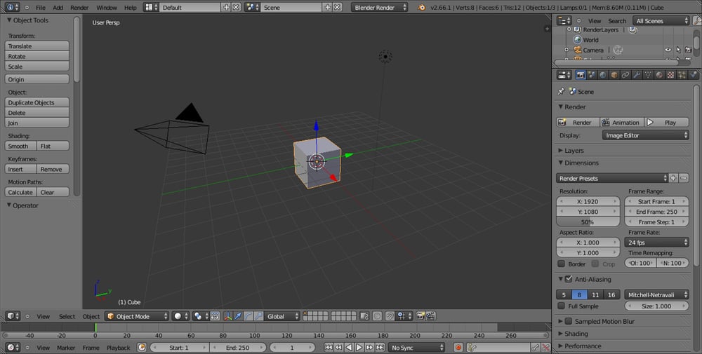
In the upper menu bar, switch from Blender Render to Cycles Render (hovering with the mouse on this button shows the Engine to use for rendering label).
Now split the 3D view into two horizontal rows and change the upper one in to the Node Editor window by selecting the menu item from the Editor type button at the left-hand corner of the bottom bar of the window itself. The Node Editor window is, in fact, the window we will use to build our shader by mixing the nodes (it's not the only way, actually, but we'll see this later).
Put the mouse cursor in the 3D view and add a plane under the cube (press Shift + A and navigate to Mesh | Plane). Enter edit mode (press Tab), scale it 3.5 times bigger (press S, digit 3.5, and hit Enter) and go out of edit mode (press Tab). Now, move the plane one Blender unit down (press G, then Z, digit -1, and then hit Enter).
Go to the little icon (Viewport Shading) showing a sphere in the bottom bar of the 3D view and click on it. A menu showing different options appears (Bounding Box, Wireframe, Solid, Texture, Material, and Rendered). Select Rendered from the top of the list and watch your cube being rendered in real time in the 3D viewport.
Now, you can rotate or/and translate the view or the cube itself and the view gets updated in real time (the speed of the update is only restricted by the complexity of the scene and by the computing power of your CPU or of your graphic card).
Let's learn more about this:
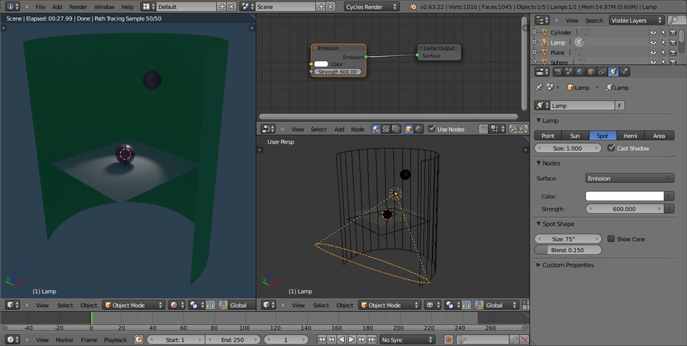
Select Lamp in the Outliner (by default, a Point lamp).
Go to the Object Data window under the Properties panel on the right-hand side of the interface.
Under the Nodes tab, click on Use Nodes to activate a node system for the selected light in the scene; this node system is made by an Emission closure connected to a Lamp Output node.
Go to the Strength item, which is set to 100.000 by default, and start to increase the value—as the intensity of the Lamp increases, you can see the cube and the plane rendered in the viewport getting more and more bright, as shown in the following screenshot:

We just prepared the scene and had a first look at one of the more appreciated features of Cycles: the real-time rendered preview. Now let's start with the object's materials:
Select the cube to assign the shader to, by left-clicking on the item in the Outliner, or also by right-clicking directly on the object in the Rendered viewport (but be aware that in Rendered mode, the object selection outline usually around the mesh is not visible because, obviously, it's not renderable).
Go to the Material window under the Properties panel: even if with the default Factory Settings selected, the cube has already a default material assigned (as you can precisely see by navigating to Properties | Material | Surface). In any case, you need to click on the Use Nodes button under the Surface tab to activate the node system; or else, by checking the Use Nodes box in the header of the Node Editor window.
As you check the Use Nodes box, the content of the Surface tab changes showing that a Diffuse BSDF shader has been assigned to the cube and that, accordingly, two linked nodes have appeared inside the Node Editor window: the Diffuse BSDF shader itself is already connected to the Surface input socket of a Material Output node (the Volume input socket does nothing at the moment, it's there in anticipation of a volumetric feature on the to-do list, and we'll see the Displacement socket later).
Put the mouse cursor in the Node Editor window and by scrolling the mouse wheel, zoom in to the Diffuse BSDF node. Left-click on the Color rectangle: a color wheel appears, where you can select a new color to change the shader color by clicking on the wheel or by inserting the RGB values (and take note that there are also a color sampler and the Alpha channel value, although the latter, in this case, doesn't have any visible effect on the object material's color):

The cube rendered in the 3D preview changes its material's color in real time. You can even move the cursor in the color wheel and watch the rendered object switching the colors accordingly. Set the object's color to a greenish color by setting its RGB values to
0.430,0.800, and0.499respectively.Go to the Material window and, under the Surface tab, click on the Surface button, which at the moment is showing the Diffuse BSDF item. From the pop-up menu, select the Glossy BSDF shader item. The node now also changes in the Node Editor window and so does accordingly the cube's material in the Rendered preview, as shown here:

Note that although we just switched a shader node with a different one, the color we set in the former one has been kept also in the new one; actually, this happens for all the values that can be kept from one node to a different one.
Now, because in the real world a material having a 100 percent matte or reflective surface could hardly exist, a more correct basic Cycles material should be made by mixing the Diffuse BSDF and the Glossy BSDF shaders blended together by a Mix Shader node, in turn connected to the Material Output node.
In the Material window, under the Surface tab, click again on the Surface button that is now showing the Glossy BSDF item and replace it back with a Diffuse BSDF shader.
Put the mouse pointer in the Node Editor window and, by pressing Shift + A on the keyboard, make a pop-up menu appear with several items. Move the mouse pointer on the Shader item, it shows one more pop-up where all the shader options are collected.
Select one of these shader menu items, for example, the Glossy BSDF item. The shader node is now added to the Node Editor window, although not connected to anything yet (in fact, it's not visible in the Material window but is visible only in the Node Editor window); the new nodes appear already selected.
Again press Shift + A in the Node Editor window and this time add a Mix Shader node.
Press G to move it on the link connecting the Diffuse BSDF node to the Material Output node (you'll probably need to first adjust the position of the two nodes to make room between them). The Mix Shader node gets automatically pasted in between, the Diffuse node output connected to the first Shader input socket, as shown in the following screenshot:

Left-click with the mouse on the green dot output of the Glossy BSDF shader node and grab the link to the second input socket of the Mix Shader node. Release the mouse button now and see the nodes being connected.
Because the blending Fac (factor) value of the Mix Shader node is set by default to
0.500, the two shader components, Diffuse and Glossy, are now showing on the cube's surface in equal parts, that is, each one at 50 percent. Left-click on the Fac slider with the mouse and slide it to0.000. The cube's surface is now showing only the Diffuse component, because the Diffuse BSDF shader is connected to the first Shader input socket that is corresponding to a value set to0.000.Tip
Downloading the example code
You can download the example code files for all Packt books you have purchased from your account at http://www.packtpub.com. If you purchased this book elsewhere, you can visit http://www.packtpub.com/support and register to have the files e-mailed directly to you. The high resolution colored images of the book can also be found in the code bundle.
Slide the Fac slider value to
1.000and the surface is now showing only the Glossy BSDF shader component, which is, in fact, connected to the second Shader input socket corresponding to a value set to1.000.Set the Fac value to
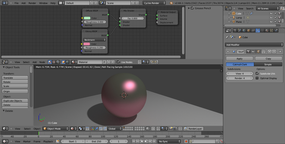
0.800. The cube is now reflecting on its sides, even if blurred, the white plane, because we have a material that is reflective at 80 percent, matte at 20 percent, and so on:
Lastly, select the plane, go to the Material window and click on the New button to assign a default whitish material.
So, in its minimal form, a Cycles material is made by a closure (a node shader) connected to the Material Output node; by default, for a new material, the node shader is the Diffuse BSDF with RGB color set to 0.800, and the result is a matte whitish material (with the Roughness value at 0.000 actually corresponding to a Lambert shader). The Diffuse BSDF node can be replaced by any other one of the available shader list. For example, by a Glossy BSDF shader as in the former cube scene, which produces a totally mirrored surface material.
As we have seen, the Node Editor window is not the only way to build the materials; in the Properties panel on the right-hand side of the UI, we have access to the Material window, which is usually divided as follows:
The material name, user, and the datablock tab
The Surface tab, including in a vertical ordered column only the shader nodes added in the Node Editor window and already connected to each other
The Displacement tab, which we'll see later
The Settings tab, where we can set the object color as seen in the viewport in not-rendered mode (Viewport Color), the material Pass Index, and a Multiple Importance Sample option
The Material window not only reflects what we do in the Node Editor window and changes accordingly to it (and vice versa), but also can be used to change the values, to easily switch the closures themselves and to some extent to connect them to the other nodes.
The Material and the Node Editor windows are so mutual that there is no prevalence in which one to use to build a material; both can be used individually or combined, depending on preferences or practical utility. In some cases, it can be very handy to switch a shader from the Surface tab under Material on the right (or a texture from the Texture window as well, but we'll see textures later), leaving untouched all the settings and the links in the node's network.
There is no question, by the way, that the Material window can become pretty complex and confusing as a material network grows more and more in complexity, while the graphic appearance of the Node Editor window shows the same network in a much more clear and comprehensible way.
Looking at the Rendered viewport, you'll notice that the image is now quite noisy and that there are white dots in certain areas of the image; these are the infamous fireflies, caused mainly by transparent, luminescent, or glossy surfaces. Actually, they have been introduced in our render by the glossy component.
Follow these steps to avoid them:
Go to the Render window under the Properties panel. In the Sampling tab, set Samples to 100 both for Preview and Render (they are set to 10 by default).
Set the Clamp value to 1.00 (it's set to 0.00 by default). Go to the Light Paths tab and set the Filter Glossy value to 1.00 as well. The resulting rendered image, as shown here, is now a lot more smooth and noise free:

Save the blend file in an appropriate location on your hard drive with a name such as
start_01.blend.
Samples set to 10 by default are obviously not enough to give a noiseless image, but are good for a fast preview. We could also let the Preview samples as default and increase only the Render value, to have longer rendering times but a clean image only for the final render (that can be started, as in BI, by pressing the F12 key).
By using the
Clamp value, we can cut the energy of the light. Internally, Blender converts the image color space to linear. It then re-converts it to RGB, that is, from 0 to 255 for the output. A value of 1.00 in linear space means that all the image values are now included inside a range starting from 0 and arriving to a maximum of 1, and that values bigger than 1 are not possible, so usually avoiding the fireflies problem. Clamp values higher than 1.00 can start to lower the general lighting intensity of the scene.
The Filter Glossy value is exactly what the name says, a filter that blurs the glossy reflections on the surface to reduce noise.
Be aware that even with the same samples, the Rendered preview not always has a total correspondence to the final render, both with regards to the noise as well as to the fireflies. This is mainly due to the fact that the preview-rendered 3D window and the final rendered image usually have very different sizes, and artifacts visible in the final rendered image may not show in a smaller preview-rendered window.
In this recipe, we'll see the several kinds of textures available in Cycles and learn how to use them with the shaders.
Similar to Blender Internal, we can use both procedural textures and image textures in Cycles. However, the Cycles procedural textures are not exactly the same as in Blender Internal; some are missing because of being replaced by an improved version (for example, Clouds has been replaced by particular settings of the Noise Texture) and a few are new and exclusive to Cycles.
We have already seen a simple construction of a basic Cycles material by mixing the diffuse and the glossy ("specular") components of a surface. Now let's have a look at the textures we can use in Cycles to further refine a material.
Because Cycles has a node-based system for the materials, the textures are not added in their slot under a tab as it is in Blender Internal, but they just get added in the Node Editor window and directly connected to the input socket of the shaders or other kind of nodes. This gives a lot more flexibility to the material creation process, because this way a texture can be used to drive several options inside the material network.
Starting from the previously saved
start_01.blendblend file, where we already had set a simple scene with a cube on a plane and a basic material, select the cube and go to the Object Modifiers window under the Properties panel to the right of the UI.Assign to the cube a Subdivision Surface modifier, set the Subdivisions level to 4, both for View as for Render.
In the Object Tools panel to the left of the 3D window, under Shading, set the subdivided cube (let's call it spheroid from now on) to Smooth.
Just to make things clearer, click on the color box of the Glossy BSDF shader to change it to a purple color (RGB set to 0.800, 0.233, and 0.388 respectively). Note, only the glossy reflection part on the spheroid is now purple, whereas the rest of the surface, the diffuse component, is still greenish.
Save the blend file and name it
start_02.blend.
Put the mouse pointer in the Node Editor window and press Shift + A.
In the contextual menu pop-up, go to the Texture item, just under Shader, and left-click on Wave Texture to add the texture node to the Node Editor window.
Grab and connect the Color yellow output socket of the texture to the yellow input socket of the Diffuse shader, the one close to the Color rectangle that we had formerly set as a greenish color:

In the Wave Texture node, change the Scale value to
8.500, Distortion to12.000, Detail to a maximum value of16.000, and the Detail Scale value to6.000.Now disconnect the texture color output from the Diffuse node and connect it to the color input socket of the Glossy shader:

Now disconnect the texture color output from the Glossy shader. Grab and connect the texture node's Fac output to the Roughness input socket of the Glossy BSDF shader, as shown in the following screenshot:

Save the file.
Delete the Wave Texture node (X key), press Shift + A with the mouse pointer in the Node Editor window and add a Checker Texture node.
Connect the Fac output of the Checker Texture node to the Fac input socket of the Mix Shader node, as shown here:

Save the file as
start_03.blend.
As is immediately visible in the Rendered viewport, at the moment the Wave Texture node color output is connected to color input of the Diffuse BSDF shader node, the spheroid looks as if it's painted in a black and white series of bands; actually, the black and white bands output of the texture node override the green color of the diffuse component of the shader, while keeping the material's pink glossy component unaltered (steps 1 to 3).
Exactly the opposite as you disconnect the texture output from the diffuse to connect it to the Glossy shader color input. Now we have the diffuse greenish color back and the pink has been overridden, while the reflection component is visible only inside the white bands of the wave texture (step 4 and 5).
In addition to the color output, every texture node has also a Fac output socket, outputting gray-scale linear values: connected to the Roughness input socket of the Glossy shader, the texture is working has a factor for its reflectivity. The working texture has a factor for its reflectivity; the spheroid keeps its colors and gets the specular-mirrored component only in the white-colored areas on the surface (that is, white bands equal to total reflecting and black bands equal to no reflection; step 6).
The Checker Texture fac (factor) output connected to the Fac input socket of the Mix Shader node works in a similar way: the numeric slider for the mixing factor on the Mix Shader node has disappeared, because now we are using the black and white linear values of the Checker Texture fac output as a factor for the mixing of the two components—the Diffuse and the Glossy—which, therefore, appear on the spheroid surface accordingly to the black and white quads (steps 8 and 9).
Every texture node has several setting options; all of them have the Scale value to set the size, the others change accordingly to the type of texture.
At this point you could wonder: "ok, we just mapped a texture on the spheroid, but what's the projection mode of this mapping?"
Good question. By default, if not specified and if the object doesn't have any UV coordinates yet, the mapping is Generated, which is the equivalent of the Original Coordinates mode (now renamed Generated as well) in Blender Internal.
But what if I want to specify a mapping method? Then, just follow these steps:
Press Shift + A on the keyboard with the mouse pointing in the Node Editor window again, go to the Input item and select the Texture Coordinate item, which is a node with several mapping modes and their respective output sockets.
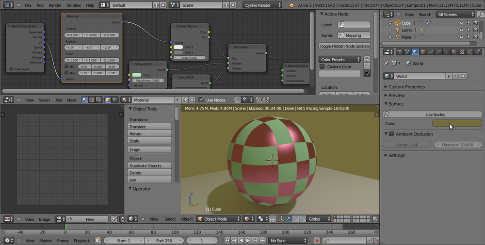
Try to connect the several outputs to the Checker Texture | Vector input (the blue socket on the left-hand side of the node) to see the texture mapping on the spheroid change in real time, as shown in the following screenshot:

By the way, I'd like to point your attention to the UV coordinates output. Connect the link to the texture's vector socket and see the mapping on the spheroid disappear. Why is this? Put simply, because we haven't assigned any UV coordinates to our spheroid yet. Follow these steps to do so:
Go in the UV Maps tab in the Object Data window under the Properties panel on the right and click on the + sign. This just adds a one-to-one Reset UV projection UV layer to the object, that is, every face of the mesh is covering the whole area of the UV window (remember that although the cube looks like a spheroid now, this is only due to the effect of the assigned Subdivision Surface modifier; the UV coordinates work at the lowest level of subdivision, which is still a six-face cube).
A second option is to just place the proper seams on the cube's edges and directly unwrap the object in an UV/Image Editor window. Press Tab to go to edit mode, press A to select all the vertexes (if the vertexes are deselected). Now, press U and chose an unwrapping method from the pop-up menu (Smart UV Project and Cube Projection don't even need the seams), then go out of edit mode to update the Rendered preview.
The Texture Coordinate node is not needed in the case you unwrap an object and then use an Image Texture node, because in that case Cycles will automatically use the available UV coordinates to map the image map.
Obviously, the Texture Coordinate node alone is not enough. What we need now is a way to offset, rotate, and scale this texture on the surface:
Select the Texture Coordinate node and grab it to the left of the window, as far as suffices to make room for a new node. In the Add menu, go to Vector and choose Mapping.
Grab the Mapping node on the middle of the link that is connecting the Texture Coordinate node to the Checker Texture node; it will be automatically pasted in-between them, as shown in the following screenshot:

Now, start playing with the values inside the Mapping node. For example, set the Z Rotation value to
45°, the X Scale value to2.000and then slide the X Location value, while looking at the texture changing orientation, dimension and actually sliding on the x axis in the Rendered viewport.Save the blend file as
start_04.blend.
The Min and Max button on the bottom of the Mapping node are used to clip the extension of the texture mapping. That is, check both Min and Max to avoid the texture to be repeated n times on the surface and shown only once. A minimum value of 0.000 and a maximum value of 1.000 give a correspondence of one to one with the mapped image. You can tweak these values to even limit or extend the clipping. This is useful to map, for example, logos or labels on an object and avoiding repeating.
In this recipe, we'll see the properties and the settings of the World window in Cycles.
The main characteristic of the Cycles World is that it can emit light, so it practically behaves as a light source. Actually, its effect is the famous "Global Illumination" effect.
As in Blender Internal, it is considered as a virtual dome at a large distance from the camera and never touching the scene's objects. Nothing in the 3D scene can affect the World. Actually, only the World can emit light on the scene and on the objects.
Open the
start_04.blendfile and go to the World window under the Properties panel to the right of the interface. This is where we see the usual Use Nodes button under the Surface tab.Although no node system for the World window is set by default, the World window has a dark medium gray color already slightly lighting the scene. Delete the default lamp or put it on a different and disabled layer to see that the spheroid in the scene is dark but still visible in the rendered 3D viewport.
It's already possible to change this gray color to some other color by clicking on the Color button right under Use Nodes (color at the horizon). This brings up the same color wheel we have seen for the shader colors. Set the color to
R 0.179,G 0.152, andB 0.047and save the file asstart_05.blend.
Note that both the intensity as well as the general color graduation of the World are driven by this color. To have more light, just move the Value slider (the vertical one) towards a whiter hue. To give a general color mood to the scene, pick a color inside the wheel. This will affect all of the scene's illumination but will show mainly in the shadows, as shown in the following screenshot:
However, to have access to all the options for the World, we have to initialize it as a node system:
Look in the bottom header of the Node Editor window, on the left-hand side of the material datablock, there are two little icons: a little cube and a little world and, yes, the cube icon is used for creating materials, while the world icon is for the World window. At the moment, because we were working on the spheroid material, the cube icon is the one selected.
Click on the little world icon. The material's node disappears and the Node Editor window is empty now, because we entered the World mode. Check the little Use Nodes box on the right of the datablock to make a default world material appear. Or else, go to the World window under the Properties panel and click on the Use Nodes button under the Surface tab, as shown here:

Also, for the World, the default material is simply made up of two nodes: a Background node connected to a World Output node. In the Background node, there are two setting options: the Color box and the Strength slider, both of which are quite self-explanatory.
Go to the World window under the Properties panel and click on the little square with a dot to the right side of the Color slot. From the resulting menu, select the Sky Texture node item. This replicates a physical sky model, with an atmospheric Turbidity value slider and the Strength slider, as shown here:

Note that you can also modify the incoming direction of the light, that is, the location of the sun, by rotating the sphere icon inside the node interface.
Save the file as
start_06.blend.Click on the Color button, which is now labeled as Sky Texture under the Surface tab in the Properties panel and select the Environment Texture node to replace it:

Looking in the Rendered view, you'll see that the general lighting has turned to a pink color. This is to show that the World material is now using a texture to light the scene, but that at the moment there is no texture yet.
Click on the Open button both in the World window under the Properties panel or in the just added node inside the Node Editor window. Browse to the
texturefolder and load theBarce_Rooftop_C_3k.hdrimage (a free high dynamic range image licensed under the Creative Commons Attribution-Noncommercial-Share Alike 3.0 License from the sIBL Archive http://www.hdrlabs.com/sibl/archive.html).To better appreciate the effect, click on the little eye icon on the side of the Lamp item in the Outliner to disable its lighting. The spheroid is now exclusively lit by the
.hdrimage assigned to the World material. Actually, you can also see the image as a background in the Rendered preview. You can also rotate the viewport and watch the background texture, "pinned" to the World coordinates, rotate accordingly in real time.As for object's materials, the mapping of any texture you are going to use for the World can be driven by the usual Mapping and Texture Coordinates nodes we have already seen. Generally, for the World materials, only the Generated coordinates output should be used, and actually it's the one used by default if no mapping method is specified. Add the Mapping and Texture Coordinates nodes and connect them to the Vector input socket of the Environment Texture node, as shown in the following screenshot:

Save the file as
start_07.blend.
But now, let's imagine a case in which we want to assign a texture to the World material and use it for the general lighting of the scene, but we don't want it to show in the background of the render. That is, for example, we are using the hdr image to light the spheroid and the plane, but we want the two objects rendered on a uniform blue background, then how to do it? This is how we do it:
One way is to go in the Render window and, under the Film tab, check the Transparent option. This will show our spheroid and plane rendered both in the 3D viewport as well as in the effective final rendered image on a transparent background, that is, with a pre-multiplied alpha channel:

It's enough, then, to compose the rendered objects with a blue background image, both in an external image editing software (such as The Gimp, to stay inside F/OSS) or directly in the Blender compositor.
But the simplest way to render the two objects on a uniform blue background is to use a Light Path node:
If it's the case, uncheck the Transparent box in the Render window to restore the sky in the preview and in the render.
Left-click the World Output node in the Node Editor window, and press G and move it to the right.
Add a Mix Shader node (press Shift + A and select Shader |Mix Shader) and move it to the link connecting the Background node to the World Output node, to paste it automatically between the two nodes. Connect it to the Surface input socket of the World Output node.
Select the Background node in the Node Editor window. Press Shift + D to duplicate and move it down.
Connect its output to the second input socket of the Mix Shader node. Click on its Color box to change the color to
R 0.023,G 0.083, andB 0.179.Now, add a Light Path node (press Shift + A and go to Input | Light Path).
Connect the Is Camera Ray output of the Light Path node to the Fac input socket of the Mix Shader node, and voilà—the objects in the scene are lit by the
hdrimage connected to the first Background node, but they appear on a "sky" that is colored as set in the Color box of the second Background node:
Save the file as
start_08.blend.
To better explain this "trick", let's say we just created two different World materials: the first one with the texture and the second one with a plain light blue color (this is not literally true, actually the material is just one containing the nodes of both the "ideally" different worlds).
We mixed these two materials by using the Mix Shader node. The upper green socket is considered equal to a value of 0.000, while the bottom green socket is considered as a value of 1.000. As the name itself suggests, the Light Path node can set the path for the rays of light that, if you remember, are shot from the camera. Is Camera Ray means that only the rays directly shot from the camera have a value of 1.000, that is, not the reflected ones, or the transmitted ones, or whatever, which instead have a value of 0.000.
So, because the textured world is connected to a socket equal to the value 0.000, we don't see it directly as a background but only see its effect on the objects lit from the reflected light or from the hdr image. The blue sky world that is connected to the value 1.000 input socket instead shows as a background because the light rays shot from the camera directly hit the sky.
Just after the Surface tab, in the World window, there is the Ambient Occlusion (AO) tab. AO is a lighting method used to emphasize the shapes or the details of a surface, based on how much a point on that surface is occluded by the nearby surfaces. Although not exactly the same thing, AO can replace, in some cases, the Global Illumination effect. For example, to render interiors having fast and noise-free results, AO is a cheap way to get an effect that looks a bit like indirect lighting.
There is a checkbox to enable AO along with the following two sliders:
The Ambient Occlusion feature is only applied to the Diffuse BSDF component of a material. Glossy or Transmission BSDF components are not affected. Instead, the transparency of a surface is taken into account. For example, a half transparent surface will only half occlude the other surfaces.
In this recipe, we will see how to create a mesh-light material to be assigned to any mesh object and used as source light to light the scene.
Until now we have used the default lamp (a Point light) already present in the scene for lighting the scene. By enabling the node system for the lamp, we have seen that the lamp uses a material created by connecting an Emission node to the Lamp Output node.
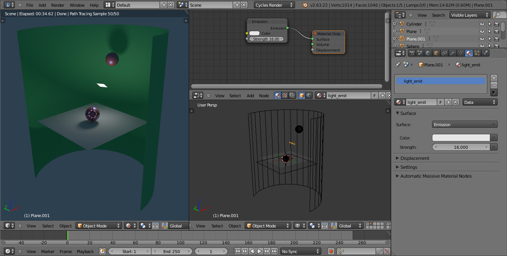
The good news is that, exactly because it's a node material, we can assign an Emission shader also to a mesh. For example, to a plane conveniently located, scaled, and rotated to point to the scene. Such a light emitting mesh is called a Mesh-light. Being a mesh, the Emission shader node output must be connected to the Surface input socket of a Material Output node instead of the Lamp Output node.
The light emission, coming from a surface and not from a point, is a lot more diffuse and softer than a lamp. A mesh-light can be any mesh of any shape and, therefore, can be easily used as an object taking part in the scene and being, at the same time, the real light source of the rendering—for example, a table lamp, or a neon sign, or a television screen. As a pure light-emitting plane, it's usually used as a sort of photographic diffuser. Two or three mesh-lights strategically placed can realistically simulate a photo studio situation.
Starting from the
start_07.blendfile, click on the eye lamp icon in the Outliner to enable it again.Right-click the lamp in the 3D view and press Shift + S to bring up the Snap menu. Left-click on the Cursor to Selected item.
Press Shift + A with the mouse pointer in the 3D view and add a plane to the scene at the cursor's location.
Come out of edit mode (press Tab). Shift select the lamp; now you have both the just added plane and the lamp selected, and the latter is the active one.
Press Crtl + C to bring up the Copy Attributes menu and select the Copy Rotation item.
Rename this plane to Emitter.
Right-click the lamp in the 3D view and press X to delete it.
Put the mouse pointer in the 3D view and press 0 from the numpad to go to Camera view.
From the Viewport Shading menu in the window header, select the Rendered mode:

Save the file as
start_09.blend.
Select the Emitter plane and click on the little cube icon on the header of the Node Editor window.
Click on the New button in the header and rename the material as Emitter.
In the Properties panel, go to the Material window and under the Surface tab, click on the Surface button to switch the Diffuse BSDF shader with an Emission shader. Leave the default color unchanged (RGB 0.800) and set the Strength slider to 35.000.
Save the file.

In the 3D view, scale the Emitter plane five times bigger (press S, digit 5, and hit Enter), then set the Strength slider to 3.500.
Save the file as
start_10.blend.
Now let's scale the Emitter plane a lot smaller (press S, digit 0.05, and hit Enter) and set the Strength slider to 350.000.
Save the file as
start_11.blend.
From step 5 to step 7, we saw how a mesh-light can be scaled bigger or smaller to obtain a softer (in the first case) or a sharper (in the second case) shadow. The Strength value must be adjusted for the light intensity to remain consistent, or the mesh-light must be moved closer or more distant from the scene.
Scaling the mesh-light basically is the same as setting the size value for a lamp. For lamps, the softness of the shadows can be set by the Size value on the left of the Cast Shadow option in the Lamp window under the Properties panel (by default, the Size value is set to 1.000). At a value of 0.000, the shadow is at its maximum crispness, or sharpness. By increasing the Size value, the softness of the shadow increases too.
Differently from the mesh-light, varying the Size value of a lamp doesn't require us to adjust the Strength value to keep the same light intensity.
In several cases, you would want the emitters to not appear in your render. There are node arrangements to accomplish this (by using the Light Path node in a very similar way to the Setting the World material recipe we have seen before), but the easiest way to do this is as follows:
Start with the last saved blend (
start_11.blend) with the 3D window on the left also set to the Rendered mode, to see the scene out of the Camera view (so the Emitter plane is rendered too).With the Emitter plane still selected, go to the Object window under the Properties panel.
Look in the Ray Visibility tab (usually, at the bottom of the Properties window), where there are five items: Camera, Diffuse, Glossy, Transmission, and Shadows with corresponding checked boxes.
Uncheck the Camera item and watch the Emitter plane disappear in the rendered 3D window, but the scene still lit by it, as shown in the following screenshot:

By checking any one of the items, the corresponding property won't take part in the rendering. In our case, by unchecking the Camera box, the mesh won't be rendered, although still emitting light. Be careful that, at this moment, the Emitter plane is not renderable but, because all the other items in the tab are still checked, it can be reflected, and if this is the case, can cast its own shadow on the other objects.
Now reselect the spheroid (remember that, unless you have renamed it, its name in the Outliner still shows as Cube). Next, from the Ray Visibility tab in the Object window under the Properties panel, uncheck the Camera item as well.
Now the spheroid has disappeared, but it's still casting its shadow on the plane, as shown in the following screenshot:

Now uncheck the Camera and the Shadow checkboxes. In this case, the spheroid is visible again but is not casting any shadow, as shown here:

Save the file as
start_12.blend. Let's try tweaking this a little.Check the Shadow box for the spheroid and select the bottom plane.
In the Material window under the Properties panel, switch the Diffuse BSDF shader with a Glossy BSDF shader. The bottom plane is now acting as a perfect mirror, reflecting the spheroid and the
.hdrimage, which we had formerly set in the World material.Go back to the Object window and reselect the spheroid. In the Ray Visibility tab, uncheck the Glossy item and watch the spheroid still rendered but no more reflected by the mirroring plane, as shown here:

Save the file as
start_13.blend.
The Ray Visibility trick we've just seen, of course, is not needed for lamps, because a lamp cannot be rendered in any case. At the moment, only Point, Spot, Area, and Sun lamps are supported inside Cycles; Hemi lamps are rendered as Sun lamps.
Both lamps and mesh-lights can use textures to, for example, project colored lights on the scene, but only a mesh-light can be unwrapped and UV mapped with an image map.
More, it seems that mesh-lights work better than lamps in Cycles, that is, the light casting and diffusion looks better and more realistic with an emitting plane. It's not clear if this is just a technical lamp limitation or if it will be improved in the future.
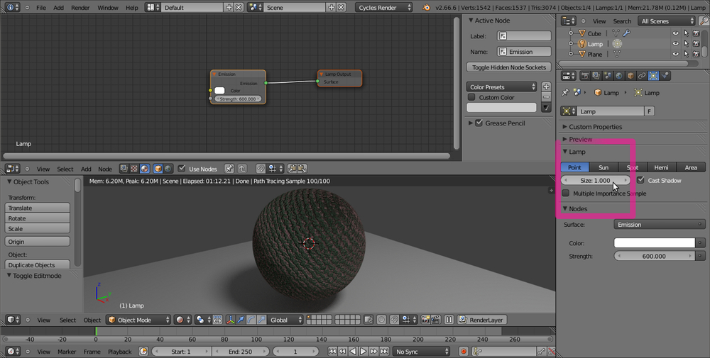
One advantage lamps have on mesh-lights is that they are easily made unidirectional, that is, apart from Point lamps, they cast light in only one direction, as shown in the following screenshot:
In the preceding screenshot, you can see that only the plane and the sphere in front are lit by the Spot lamp. With a mesh-light plane replacing the Spot lamp, instead, both the sphere and the cylindrical green wall behind are lit, as shown here:
So what if we want to only light the object in one direction (plane and sphere in front) with a mesh-light? Is there a way to make a light-emitting plane to emit it only from one side and not the opposite one? Yes, of course, there is:
Open the
1301OS_01_meshlight.blendfile, which has a prepared scene similar to the one used for the preceding screenshots, and set the bottom 3D window to the Rendered mode by clicking on the Viewport Shading button in the header and selecting the upper item.Left-click the Emitter item in the Outliner and put the mouse pointer in the Node Editor window. Add a Mix Shader node (press Shift + A and go to Shader | Mix Shader) and move it to the link connecting the Emission node to the Material Output node to paste it in between.
Add a Geometry node (press Shift + A and go to Input | Geometry) and connect its Backfacing output to the Fac input socket of the Mix Shader node.
Switch the Emission node output from the first Shader input socket of the Mix Shader node to the second one, as shown in the following screenshot:

Save the file as
1301OS_01_meshlight_final.blend.
The plane is now emitting light only in one direction.
We have already seen that in a Mix Shader node the first (upper) green Shader input socket is considered equal to a 0 value, while the second one to a 1 value. So, the Backfacing output of the Geometry node is stating Cycles to make the plane emit light only in the face-normal direction, and to keep black and non-emitting (just like a blank shader) the opposite "backfacing" side of the plane.
By switching the Emission node connection to the first Mix Shader input sockets, it's obviously possible to invert the direction of the light emission.
To obtain both bumps and displacement effect in Cycles, there are a few options.
The simplest way to have bumps on our material's surface is by connecting the Color or the Fac output of a texture node to the Displacement input socket of the Material Output node. Despite the fact that the socket's name is Displacement, the effect I'm writing at the moment is just a simple bump effect (by the way, a very good one), affecting as a whole the total result of the sum of the material's nodes.
Just as we did for color textures, the bump textures can also be mapped on the object with the Mapping and Texture Coordinate nodes. There is naturally also a way to set the amount (the strength) of bumpiness of the texture on the object's surface:
Open the
start_02.blendfile and set the 3D view to the Rendered mode.Put the mouse pointer in the Node Editor window and press Shift + A to bring up the Add menu and select a Math node from the Convertor item (press Shift + A and go to Convertor | Math).
Connect the Fac output of the Wave Texture node, already connected to the Roughness input socket of the Glossy BSDF shader node, to the first upper gray Value input socket of the Math node. Connect the Math node output to the Displacement input socket of the Material Output node.
Set the operation mode of the Math node to Multiply. By sliding the second Math node Value, we can set the influence, the strength, of the bumping. Try, for example, to set it to 3.000, as shown in the following screenshot:

Save the file as
start_14.blend.
Put simply, the gray-scale values of the texture are multiplied for the value we put in the second slider of the Math node. For example, if we set a value of 0.500, the intensity of the effect will be the half of the default one (1.000 x 0.500 = 0.500). With a value of 3.000, the effect will be three times the default one. Similar to Blender Internal, the value can also be set as negative (-3.000 in this case), thereby inverting the direction of the bump effect.
Note that there is an evident problem at the terminator of the spheroid (that is, at the limit of the lit surface with the self-shadowed one) that seems as a general limit of path tracers. To get rid of it, you can try to subdivide the mesh by a higher value (a little impractical method, honestly), but this not always is enough. A different way is to modify the Size value of the lamp (or the scale if you are using a mesh-light). Select the lamp in the Outliner, and in the Size button under the Type of Lamp row in the Object Data window, set Size to 1.000. The terminator looks a lot smoother now (along with also, obviously, the projected shadow on the plane):
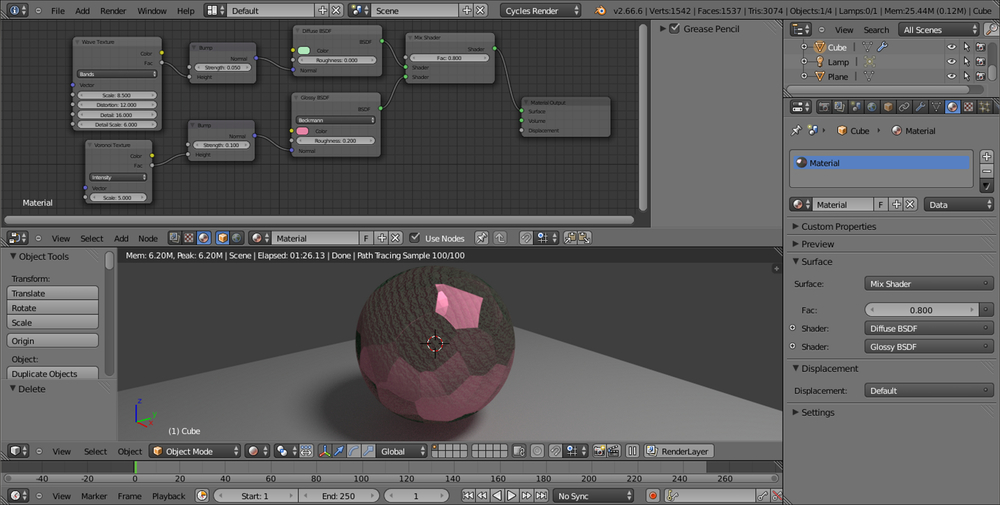
From Blender 2.65 onwards, a Normal input socket has been added to all the appropriate shader nodes, to input values for the bump of each shader node itself. This input socket must be fed by a Bump node (press Shift + A and go to Vector | Bump). This is how we do so:
Starting from the
start_14.blendfile, select the Math node in the Node Editor window and delete it (press X).Put the mouse pointer in the Node Editor window and press Shift + A to add a Bump node (press Shift + A and go to Vector | Bump).
Connect the Fac output of the Wave Texture node to the Height input socket of the Bump node and the output of the latter to the Normal input socket of the Diffuse BSDF shader node. Set the Strength value to
0.050.Add a Voronoi Texture node (press Shift + A and go to Texture | Voronoi Texture) and a new Bump node (press Shift + A and go to Vector | Bump). Connect the Fac output of the Voronoi Texture node to the Height socket of the new Bump node and connect the latter to the Normal input socket of the Glossy BSDF shader node:

Save the file as
start_15.blend.
As you can see in the preceding image, it's now also possible to have the bump effect per node. That is, every shader node can have a different bump with different strength (note that it's no more needed to connect anything to the Displacement input socket of the Material Output node). This way, we can have a certain bump effect only on an established component of the shader (the diffuse shader), and a different bump on the other components (the glossy shader), as shown here:
As far as displacement is concerned, we can use the Displace Modifier option in the Object Modifiers panel, using a texture to be set in the Textures tab under the Properties panel. It seems no Cycles texture can be used for this at the moment, but only the old Blender Internal textures at disposal from a menu. In this case, the displacement is not behaving any differently from the displacement we have in BI. The mesh must be subdivided (usually the Subdivision Surface modifier is used, but also the Multiresolution modifier can be used) and then displaced. In short, there is nothing as a "micro-polygon displacement rendering" yet.
By the way, by enabling Experimental in the Feature Set tab under Render in the Render window, it's possible to have access to a (still incomplete) displacement feature:
Go to the Render window under the Properties panel. In the Render tab click on the Feature Set button, by default labeled with Supported, and select Experimental.
Go to the Object Data window to find a new tab named Displacement, where we can choose between three options: Bump, True, or Both (the Use Subdivision and Dicing Rate buttons don't seem to work yet).
Note
Bump will give us the average bump effect, which is the same as connecting the texture output in the Displacement input of the Material Output node (that we'll have to do in any case).
By setting the method to True, we can have a displacement effect not different from the Displace Modifier output, and the mesh must be subdivided.
Both will use the texture gray-scale values' information for a displacement and the bump effect together.
Select True.
Reselect the spheroid. Go in the Material window under the Properties panel, and in the Displacement tab click on the blue Value button labeled Wave Texture to select an Image Texture node from the pop-up menu.
Click on the Open button, browse to the
texturesfolder, and load thequads.pngimage.Just under the Open button, click on the Color Space button to set it to Non-Color Data.
Split the bottom 3D window to open a UV/Image Editor window. Press Tab to go in edit mode and then press U with the mouse pointer in the 3D window. In the UV Mapping menu, select Smart UV Project, then press Tab again to go out of edit mode (this is a quicker way of unwrapping the spheroid which, remember, at its lower level of subdivision is still a cube. If you want, you can do a better unwrapping by placing seams to unfold it and by selecting a normal Unwrap from the menu).
Go to the Object Modifiers window and raise the Subdivisions levels for both View and Render to
6:
In any case, this is just for a temporary demonstration, the feature is still incomplete and at the moment seems to work (quite) properly only if the texture is mapped with UV coordinates. This is definitely going to change in the future.