


One of the most common scenes to create using Computer Graphics is a space scene. Many well-known space movie scenes come to mind when thinking about it and, of course, the very mood by itself is an interesting motivation to accomplish the task. In this chapter we're going to make a space scene, mixing some techniques to get a believable environment and create models that give the illusion of massive objects, a spaceship in this case.
Our job is to create a scene in space where a few fighters are attacking a mother ship. To give the right mood to the scene we'll add a simple background comprised of a big planet and a nebula background.
Let's make a simple sketch to plan the scene beforehand, so that the actual modeling, texturing, lighting, and compositing work are clearly understood; that way it is possible to have a clear picture of the whole project from the very beginning, which helps a lot in focusing the effort on what really needs it.
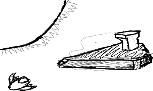
The previous sketch shows the elements that will be needed to create our nice render of a ship being attacked by a few fighters, accompanied by a planet and a simple stars and nebula background.
We'll be working on producing a believable mother ship, though we'll avoid modeling detailed elements—Since the camera is going to be far enough away, details won't be distinguishable. The actual shader for the mother ship will be the default one, because we're going to take care of its look by using compositing techniques. Space fighters will be modeled after a basic style distinct from the mother ship, and will include a couple of simple shaders. The finishing touches of the scene will be done by modeling and texturing the planet, creating a simple background with stars and nebula, and adding an energy shield to the mother ship—Even if there are just a few space fighters, it's better to protect the ship! Finally, we'll take all the elements and composite them to get a more polished look than the one produced by the render engine alone.
In this project we will create two basic models by using common modeling techniques and applying some very useful tools that help in reducing the time required and complexity for some tasks.
The background for the scene is going to be composed of two elements: A planet and a nebula. The planet itself doesn't pose a problem at all, but the nebula will give us the opportunity to play a bit with a particles system and perform some magic with the Node Editor.
For the energy shield, we're going to use a moderately complex shader, which includes some ramps and a few textures. Since this shield is the most attractive element in the whole scene, we're going to learn how to have a total control on the impacts that it receives, using a group of lamps.
Finally, we'll be working on the compositing of the Final Scene, separating objects in RenderLayers and creating a moderately complex setup that will add some effects such as glow and perform certain color manipulations to give a better look to the render.
This project will help us learn some basic, but very cool techniques that can add more visual richness to our work; we'll also learn to effectively use some tools available in Blender 3D that are not so well known.
In the modeling area, we're going to learn how to use a very nice script for populating procedurally generated geometry on an object; this is very useful for giving visual richness to objects that must look complex, but will not be seen closely by the viewer. On the other part, we'll look at a way of effectively using the Proportional Edit, which will help us to form a nice, curvy shape for one of our models, without having to manually tweak every single vertex.
For the shading part, we'll be creating a basic rusty-metal shader, using just procedural textures. We'll also apply a very common technique to get nice looking reflections by using a texture.
Last, but not least, the compositing techniques that we'll work with are quite a few: creating a nebula look from just a few dots, adding surrounding glow to an object, and enhancing colors, contrast, and brightness in an image. These techniques are quite useful since they allow us to drastically affect the look of a rendered image without having to re-render it; they're also useful to perform some types of corrections in a very friendly and controlled way.
Our work can be summarized in seven activities, as follows:
Modeling the mother ship.
Modeling the space fighter.
Shading the space fighter.
Modeling and shading the planet.
Creating the nebula background.
Assembling and organizing the final scene.
Compositing the final scene.
In this project we'll need Blender 2.49b for using a special script that hasn't been ported yet—as of writing this book—to Blender 2.50. If you haven't installed Blender 2.49b, now is a good time to do so.
We also need to download two textures: A cold cloudy sky to be used as a reflection map in a couple shaders and the diffuse map for the planet in the background.
A good place to find free textures on the Internet is www.cgtextures.com. The licensing of their textures is open to both private and commercial use, under some restrictions (see license page at http://www.cgtextures.com/content.php?action=license). Let's go there and download the image called Skies0263 (http://www.cgtextures.com/texview.php?id=18926) from the Skies Partial section; this image has a strong stormy look. A good guide to find it is looking at the URL of the link and checking for the ID 18926. This image was chosen because it has blue spots, cloudy spots, strong contrast, and a cold mood; that way it will look nicer when acting as reflection map.
To get the texture for the planet, let's go to www.nasa.gov and download one of the free planet maps (http://www.nasa.gov/zip/272246main_ven0aaa2.jpg.zip). As of writing this book, the images can be found by selecting Multimedia → 3D Resources in the homepage, then choosing Images and Textures in the list of categories; make sure to download a projected map, not a normal photo of the planet; also pay attention to the resolution and quality of the image, since the planet is going to be quite big in the final render, resolution is very important. For the explanation we'll be using the Venus texture map, which has a width of 1440 pixels and a height of 720 pixels, good enough for our purposes.
Before starting work on it, let's discuss how we are going to organize our project. Splitting the project into smaller parts is very convenient to avoid having to work with a cluttered viewport at some point. For the sake of simplicity, we are going to organize our project in the following manner:
One file containing everything
Separated scenes for the mother ship, the space fighters, the planet, and the nebula
One main scene to bring together everything (except for the nebula scene) and composite the final render
It is suggested to have a folder exclusively for this project's files. A good file name could be
space-scene.blend. Do not forget to save as often as possible while working on the project and use incremental saving, by using the plus button on the right-hand side of the filename text entry in the file browser, this way we have an easy way to revert when errors occur.
Now that we have a clear idea of what we're going to create, along with the way to organize our objects, it's time to fire up Blender 2.50, save the file with the proper file name and start the ride.
What we'll be doing first is create the model for the mother ship. This model will need some work to define its general shape; however, the hard part of it will be taken care of by a very useful script bundled with Blender 2.49b. We'll start working with Blender 2.50, and indicate explicitly when to switch to Blender 2.49b.
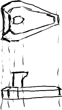
The modeling of the actual ship is going to be done by free modeling, without using any blueprint on the viewport; that said, it's important to emphasize that it doesn't mean we should work without having a clear idea of what to model, so it's best to have a sketch of the model:
Let's change the name for the default scene to Mother Ship, select the default cube and delete it (X key or the Delete key); the camera and light can be left in, so we can perform some render tests if needed. Remember the menu entries indicated are from the menu located in the 3D View header (horizontal bar at the bottom).
Set the 3D viewport to Top View by going to View → Top (Numpad 7), orthographic mode (View → View Persp/Ortho or Numpad 5), and make sure the 3D Cursor is located at (0,0,0); if it isn't, go to View → Align View → Center Cursor and View All (Shift C).
Now add a plane and enter Edit Mode. Select the two vertices forming the rightmost edge (vertical edge) and move it -1 unit along the X axis (G key, X key, then type "-1"); then scale it by a factor of 1.6 (S key, then type "1.6") to create a trapezoid shape and continue by extruding and moving the extruded edge straight along the positive X axis by 0.5 units (E key, Esc key, G key, X key, then type "0.5").
Finish the basic shape by extruding the rightmost edge, moving the extruded edge along the positive X axis by 3.6 units (E key, Esc key, G key, X key, then type "3.6") and scaling it by a factor of 0.16 (S key, then type "0.16") to get a short edge. The important thing to pay attention to here is not the exact measurements, but the shape of the object and how the proportions work to give some sense of form. Go ahead and play with the proportions until they look nice; be careful to keep the edges correctly aligned. Here is a screenshot to show what the model should look like by now:

With the basic shape in place, we can now switch to Edge Select Mode (Ctrl + Tab) and select only the edges surrounding the shape.
Switch to Front View (Numpad 1) and extrude the selected edges upwards; moving the extruded edges 0.5 units along the positive Z axis (G key, Z key, then type "0.5") should be okay if you didn't change the size of the model too much from the suggested measures; in this case we don't want the extrusion to be too short because it would make the ship look too flat, but should also avoid moving the extrusion too much, since that will cause the 3D shape to not look like a ship. If the proportions are causing any kind of doubt or trouble, a good thing to do is to play a bit, moving the extruded edges along the Z axis and rotating the view around the model; that way we can get a feel for how well the shape looks in each case and choose the best one.
With the last extruded edges selected, we switch to Top View (Numpad 7) and extrude once again (E key); this time don't move the extrusion, just cancel the translate operation (Esc key, right after the E key) and follow it by scaling down by a factor of 0.7 (S key, then type "0.7"). Now let's take a look at a screenshot to avoid unintelligible written explanations for the next few steps:
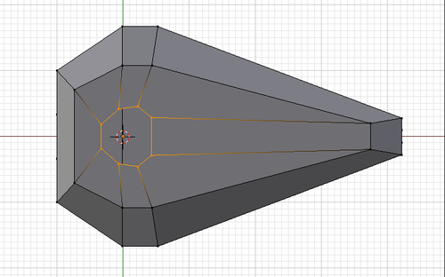
To get to the state shown in the screenshot, use the following steps:
Tweak the last extrusion from Top View to resemble the shape shown close to the border, then switch to Front View and move the entire tweaked ring around 0.16 units along the Z Axis (G key, Z key, then type "0.16"); continue by switching to Top View, then perform another extrusion, scale it down and tweak it to get the round shape shown for the inner ring.
At this point we begin modeling the ship's bridge by selecting the ring from the last extrusion, switching to Front View and extruding it 0.7 units upwards; immediately after, extrude again but this time move the extrusion 0.35 units upwards.
Finally add an edge loop by using the Loop Cut and Slide tool (located at the Tool Shelf, View → Tool Shelf, or using Ctrl + R) and clicking on the edges that run along the last extrusion—when entering the slide part of the command, cancel it by pressing Escape to get the edge loop right at the middle.
Right now we have the geometry needed to shape the bridge, but there is some tweaking needed to get the final shape that we really want; this screenshot shows the final shape of the bridge after moving some vertices around and creating three faces to close the top of it:

The basic shape of our mother ship is finished but there are some additional things we need to do to get it finalized.
Let's add more detail to the long part of the ship; locate the longest edges of the mesh (running from the side of the tip into the side and back of the ship), then start the Loop Cut and Slide tool (Ctrl + R) and create three more edge loops that run across those long edges (to increment the number of edge loops to add, scroll the mouse wheel while using the tool); these new edge loops will not only run across the side of the ship, but also up and across the bridge. This is caused by the particular way the faces of our model are organized. Name the object as
motherShipand save the file.Now it's time to open good old Blender 2.49b and use it for populating some geometry on the surface of our ship, but without having to create all that geometry by hand.
Start by deleting the default cube, and continue by appending the
motherShipobject from thespace-scene.blendfile.To do that go to File → Append or Link, locate the
space-scene.blendfile on your system and click on it. Now Blender will show all the data that the file is holding, organized in folders according to its type. Let's click on the Objects folder and then on the motherShip object name; to perform the append make sure that Append is selected in the header at the bottom of the window and click on the Load Library button. A copy of the object will be created at the current scene. If the appended object doesn't appear, look for it in the layers that are turned off.Now we need to do a vertical split of the 3D View by right-clicking on the horizontal line that separates the 3D View from the Buttons window, selecting Split Area and then clicking inside the 3D View to perform the split.
Change the 3D View at the right-hand side to a Scripts Window (not the Text Editor) and load the Discombobulator script, located at Scripts → Mesh → Discombobulator; the script interface will appear on the Scripts Window, ready to be configured and applied on the object that is selected in the 3D View on the left-hand side.
Before applying the Discombobulator we're going to select the faces that we want to be affected by the operation.
In Edit Mode, switch to Face Select Mode, select all faces and then deselect the faces on the front and side of the bridge (not the whole extrusion, just the upper part) since these faces are supposed to hold the window to see outside. It is also recommended to deselect the faces with a shape that looks too much like a triangle, since those could cause the Discombobulator script to generate some not-so-nice geometry.
The configuration for the Discombobulator is as follows:
Deselect Make Protrusions (upper left-hand side), check Only Selected Faces (middle left-hand side)
On the Doodad Properties section (middle) set:
Min Amount to 16
Max Amount to 32
Min Height to 0
Max Height to 0.02
Min Size % to 10
Max Size % to 30
Finally, make sure to deselect the Copy Before Modifying option (bottom right-hand side).
Before issuing the command, let's take a look at a screenshot, showing the faces that must be deselected and the configuration for the Discombobulator script:

We can now click on Discombobulate, at the bottom left-hand side.
Note
If Discombobulator seems to be adding no geometry to faces that are selected in the object, it is because the normals of those faces are inverted. To resolve it simply go into Edit Mode, select the faces with the problem and flip the normals by going to Mesh → Normals → Flip (W → Flip Normals). Notice that Discombobulator can reset its values when undoing the previous modification, so it may be necessary to re-enter the right values.
This will give us a nice, rich geometry addition to the surface of our ship, which seen from far enough can appear like a very elaborated model.
It's quite likely that there are some fragments of the mesh added by Discombobulator floating outside the face.
To solve that we just go into Edit Mode and select and delete those fragments; a very useful selection command to use when having so much geometry is the Select Linked command (hover your mouse pointer over the fragment and hit the L key).
To get this detailed model back into Blender 2.50 we need to perform the same trick of saving the file and then appending the object from the other instance of Blender.
Save the file in Blender 2.49b as
motherShip-detailed.blend, go to Blender 2.50, choose File → Append, and perform the same operation as we did before. Be advised that this time there can be more than one object in the file saved by Blender 2.49b, so we must look beforehand for the name of the mesh with all the details added. As before, make sure that you are appending the object, not linking it—make sure the Link checkbox is disabled in the left-hand side region of the File Browser in Blender 2.50.Note
The possibility of moving data so easily between different versions of Blender (even so much different as 2.50 vs. 2.4x series) is one of the nicest things the application has. It is allowed by the file format of Blender using a technology that kind of self describes the file content and structure; that way any Blender version can know what data from the file it can load and just ignore the parts that it doesn't understand. In this case, mesh data is 100% understandable between these versions, so we can move it freely without worrying at all. Note, though, that there are types of data that are not 100% compatible between versions.
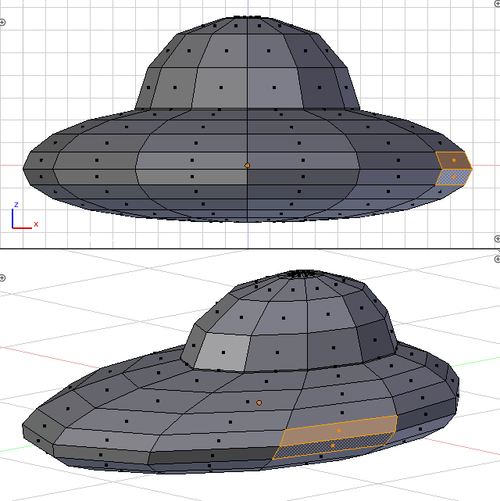
Back in Blender 2.50 we finally have a nice-looking model for our mother ship. Remember to check if the basic model is still there and delete it (or hide it; layer 20 can be a good place to hide objects that could be of use later). Let's take a look at the final model for the mother ship:
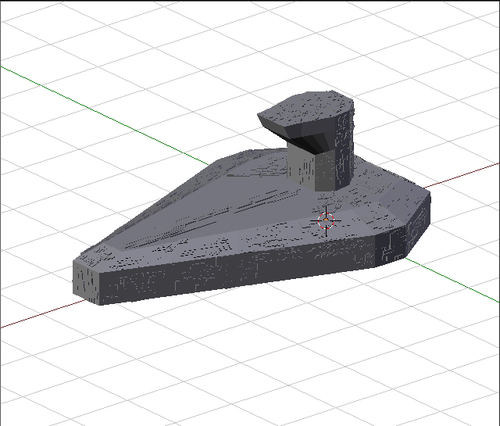
We can now save the file and go to the next part.
Modeling the mother ship was quite straightforward; we started by defining the overall shape for our mother ship, mostly paying attention to the shape and proportions of it. The finishing touches for our model were added very easily with the use of the Discombobulator script available in Blender 2.49b.
The model for the space fighter will be created starting with a sphere, then tweaking it with the nice proportional editing tool available in Blender and creating the cabin with some extrusions; the next part will be working on the wings and adding the cannon compartment and the cannon itself.

Start by creating a new scene and rename it as Space Fighter; this scene will hold the model for the fighter that will be attacking the mother ship.
We need a sphere for the body of the fighter, so create a new UV Sphere and set its segments and rings to 12, then switch to Edit Mode and Front View.
Select the vertex at the south pole of the sphere, activate proportional editing (Mesh → Proportional Editing → Enable) and set its type to smooth, then move the selected vertex upwards; pay attention to the radius of influence of the proportional editing and resize it as needed by using the mouse scroll wheel. What we are trying to accomplish now is to get the squashing effect for the body of the fighter, so that it looks more like an egg than a sphere.
The upper part of the body of the ship also needs to be squashed the same way as we did with the bottom part. This time, though, follow the squashing by a translation of the selected vertex along the positive direction of the X axis (keep the proportional editing enabled); moving it around 0.8 units should be okay; since this time the operation depends on the size of the influence, the actual values may change. At this point the body has a nicer shape than a squashed sphere, all thanks to the very handy proportional editing.
To give the finishing touch to the shape of the body, switch to Top View, select the leftmost vertex and move it along the negative direction of the X axis; around -0.8 units of translation should be okay.
We can now turn off proportional editing and make the body look more aero-dynamic by selecting all the vertices, switching to Front View and scaling it by a factor of 0.45 on the Z Axis. The whole purpose of this scaling is to make the body look more slim; we can now disable the proportional editing tool, since we don't need it for the next steps. A screenshot showing the progression of the previous steps can be very helpful:

Now we can create the cabin of the fighter. Switch to Top View and select the north pole of the shape and the vertices forming the ring immediately surrounding it. Delete the selected vertices.
Then switch to Edge Select Mode (Ctrl + Tab), select one of the edges of the border of the hole we just created, and go to Mesh → Edges → Edge Loop (Ctrl + E → Edge Loop or Alt + Right-click). That way we get all the edges selected easily. Now switch to Front View and go to Mesh → Add Duplicate (Shift + D), to create a duplicate of the selected ring, press Escape to avoid moving it. What we just did was create a ring that is located exactly where the original selection was, but completely disconnected from it; this will be the contact point between the cabin and the body.
Having the first ring for the cabin, let's extrude it five times and move the extrusions straight up; the first extrusion should be moved just slightly (the ring will be very close to the initial one), the other ones can be moved more. Each extrusion must be followed by a scaling operation; what we want to get here is an egg-like shape that will be the basis for the cabin, its height should be comparable to the height of the body. The scaling of the last extrusion should leave us with a very tiny ring (it's a good idea to not scale it completely to zero, to avoid merging the vertices and getting ugly artifacts when using the Subdivision Surfaces modifier).
As a finishing touch you can select one of the vertices of the cabin and move it along the X axis with proportional editing enabled, to break the rigid symmetry that the scaling operations left us with; be careful to preserve some symmetry since this is a mechanical model.
At this point it's a good idea to have a look at how the model should look:

Since our model is using a low number of polygons, it doesn't look really nice.
To have a nicer looking ship we can just add a Subdivision Surface modifier: Go to the Properties Editor, locate the Modifiers tab and in the drop-down menu labeled Add Modifier select Subdivision Surface; setting the subdivisions to 2 (both for View and Render) should make it look nicely curved.
Up until now we've been modeling our space fighter aligned with the X axis; to ease the rest of the modeling work, let's switch to Object Mode and rotate it 90 degrees around the Z axis (R key, Z key, then type "90"); that way the fighter will be aligned with the Y axis; remember to switch back to Edit Mode and check that proportional editing isn't enabled.
The next step is creating the wings of the space fighter. To do that switch to Face Select Mode and Front View, then locate the line where the top part and the bottom part of the ship encounter ("equatorial" edge loop) and select the two rightmost faces sharing an edge on the equatorial line. The following screenshot shows clearly the faces to be selected:
Now switch to Top View and perform a first extrusion that will be left unmoved, exactly where it starts (press the Escape key after extruding), then perform a series of three extrude-scale-rotate operations. The whole purpose of it is getting the shape of the wing resembling a horn going right and up (from Top View). Play a bit with the tweaking until the shape looks good enough.
While modeling the first wing it's quite normal to start thinking about how we are going to model the other side to be exactly symmetrical. Luckily we have a modifier that will save us all that hassle!
Go into Top View and set the 3D View mode to Wireframe (press the Z key once or twice). Deselect all the vertices (press the A key once or twice) and start the Border Select tool (Select → Border Select); now draw a rectangle containing all the vertices in the left-hand side part of the mesh; be careful to not include any of the vertices lying on the green line that represents the Y axis. Delete the selected vertices, go to the Properties Editor, select the Modifiers tab and add a Mirror modifier from the Add Modifier menu. In the Mirror modifier panel that appears, set Axis to Y (disable X) and enable Clipping. If you had preserved the Subdivision Surface modifier that we added previously, make sure it gets located below the Mirror modifier we just created by clicking on the triangle pointing down, right below the name of the modifier.
As a small tweak for the wings we can go to Top View, set the 3D View mode to Wireframe, use theBorder Select tool to select the vertices that form the join of the wing at the bottom-right part of the model and move them a bit to the back of the fighter; that way the wings have a nicer shape and the whole fighter's proportions look better.
Another possible improvement for the model could be selecting the vertices forming the wings (but not the ones in the joint with the body), locating the 3D Cursor in the joint of the wing and the body, switching to Top View, setting the pivot to be the 3D Cursor (press the Period key) and then rotating the selected vertices at will. Perform some more tweaking if you want to and rotate the view around the model to get a better sense of its shape.
As a final task to add some detail to the wings, let's disable the Subdivision Surface modifier (the eye icon in the modifier settings) and perform an extrusion to hold a cannon in each wing. Since the details of this part are hard to describe in words, let's look at a series of screenshots showing the process :

The extrusion must be done with the two faces shown selected in the first step; after extruding, let's scale it down on the X axis and then do some manual tweaking to organize it as show in the second step. For the third step just extrude the upper face and move the extrusion upwards. Finally delete the front faces for the whole shape we created (only the faces) and then perform some manual tweaking to finish it.
Of course, we also need a cannon to go with it, so here is a screenshot showing the process to create the cannon:

The first step is just creating a cylinder and scaling it appropriately. Steps 2, 3, and 4 are achieved by simply adding more edge loops (Ctrl + R) and scaling when necessary. For the final shape shown in step 4, add a few edge loops close to the ones defining the general shape; these loops will help to create a nice crease effect when applying the subdivision surface modifier. Step 5 is just the mesh from step 4 located at the final position on the wing.
This model required more detailed work. We started with a basic sphere shape and transformed it into a nice shaped space fighter by using very basic transformations and also the very useful Proportional Edit.
The cabin and wings were created by just performing some simple extrusions and tweaking as needed. The final details in the wings and the cannon demanded more hands-on tweaking in order to get a nice looking shape and enough detail for our space fighter.
One of the tools we used for modeling the space fighter is the Mirror modifier. Let's know more about its settings: The axis setting in the Mirror Modifier indicates along which axis the object will be mirrored, the actual point of symmetry for the mirror is indicated by the orange dot called Object Center. The clipping option allows us to perform an auto-merge, which is very useful to avoid creases at the mirror plane, specially when using a Subsurf modifier. Merge Limit allows us to set how far apart any two vertices can be to still be included in the merge operation.
With all the elements in the model ready, we must go into shading it. The materials that we're going to create are not too complex, because we expect most of the final look of the scene to come from the compositing setup.
We will be creating four shaders, one for each part:
Let's start by creating the materials and assigning them to the correct geometric parts of the fighter.
Go to the Properties Editor and locate the Material tab, locate the list of material slots and click on the button with the plus sign, on the right-hand side of it, until you get a total of four slots. The slots will have no names, which means that no material is assigned.
Since we need a different material for each slot, we must select each slot and click on the button with the plus sign that is below the Select button (below the material slots list; remember we are in Edit Mode). As of now we must have four slots, each one with a different material name.
Now select each material and put a name to it by modifying the text in the text field that is now located where the button used to add a material to each slot initially was; pick the name from the list of shader names given earlier.
To assign each material to the corresponding mesh faces, make sure to have Face Select Mode active, deselect all faces, and then select the cabin by using the Select Linked tool (hover the mouse pointer over that part of the mesh and press the L key), then go to the Properties Editor, select the
sf_cristalCabinmaterial, and click on the Assign button, located just below the material slots list. Do the same for the corresponding mesh parts for the other three materials. Since the body and wings are not separated mesh patches, it will be necessary to work on selecting each one by hand (Select → Border can be of help).Note
An easy way to check if each material is assigned to the correct mesh parts is to choose a different strong diffuse color for each one and check in the 3D View that each material is assigned to the correct faces in the mesh. The diffuse color is located right below the title of the diffuse panel of the material that is currently selected.
Let's now list the values for the different properties of the material
sf_cristalCabin:Diffuse color: 0.64 Red, 0.74 Green, 0.80 Blue
Specular panel:
Specular Intensity: 0.92
Specular Hardness 13
Ambient: 0.4 (Shading panel)
Let's explain what these settings are for:
Diffuse color is for giving a metal bluish color to the cabin.
Specularity settings are for getting a strong, kind of metallic specular reflection.
Ambient setting is for lowering the effect of the ambient color of the world on the material. The ambient color is like a default filling color that will affect every shader that has the Ambient setting value higher than 0.
The material for the cabin needs to have a texture to create the illusion of reflection.
Click on the Texture tab in the Properties Editor. If there is a texture called "Tex" make sure to unlink it by clicking on the X button that is below the texture slots list.
We can now select any free slot for the texture and click on the + New button that is right below the texture slots list. After adding the new texture, name it
sf_cabin_reflMapand set its type to Image or Movie; below the black preview locate the Image panel and click on the Open button. In the file browser that Blender shows, browse your system for the sky image downloaded previously.With the proper texture loaded, go down to the Mapping panel and select Reflection on the drop-down menu labeled with Coordinates. Finally go to the Influence panel and set the Diffuse Color factor to 0.65 (it must be checked). That will get this material finished.
The next material to tweak is
sf_shipBody. The main settings are as follows:Diffuse panel:
Color: 0.01 Red, 0.03 Green, 0.01 Blue
Intensity: 0.88
Specular panel:
Color: 0.92 Red, 0.98 Green, 1 Blue
Specular Shader Model: Blinn (drop-down menu on the right-hand side of the color)
Intensity: 0.3
Ramp: Enabled
Hardness: 10
IOR: 9
Ambient: 0.4 (Shading panel)
The ramp (Specular panel) must have two colors, with these settings:
First color stop:
Position: 0.083
Color: 1 Red, 0.86 Green, 0 Blue
Alpha: 0.2
Second color stop:
Position: 0.292
Color: 0.69 Red, 1 Green, 0.90 Blue
Alpha: 1
Make sure the interpolation method for the ramp is set to Linear (the default one) and the Input field is set to Shade r.
Now it's time to go and create a texture that will give a nice rusty look to the material.
Go to the Texture tab in the Properties Editor, delete any default texture that may be linked to the material and add a new one; name it
sf_body_specNoise. As the name suggests, this texture will just add noise to the specular component of the shader; the diffuse component will also be affected, but just slightly.The texture
sf_body_specNoisemust be of type Musgrave and have these settings:Musgrave panel:
Type: fBM
Dimension: 0.1
Lacunarity: 4.2
Octaves: 8
Basis: Voronoi F1
Size: 0.4
Influence panel:
Diffuse Intensity: Enabled, -0.376
Diffuse Color: Disabled
Specular Intensity: Enabled, 1
Blend: Add (drop-down menu located at the bottom left of the panel)
Now it's a good time to check the material preview and find a nice-looking rusty material.
The next material to work on is
sf_shipWings. Go to theMaterial tab in the Properties Editor and select it from the material slots list. Then set it as follows:Diffuse color: 0.26 Red, 0.22 Green, 0.20 Blue
Specular panel:
Color: 0.77 Red, 0.52 Green, 0.55 Blue
Intensity: 0.92
Specular Shader Model: Blinn
Hardness: 7
IOR: 7.2
Ambient: 0.4 (Shading panel)
To refine this material we need to go to the Texture tab in the Properties Editor and add a couple of textures. The first texture will be the same
sf_body_specNoisewe used in thesf_shipBodymaterial. To reuse an existing texture, just select an empty texture slot, click on the drop-down menu on the left-hand side of the + New button, and select the texture from the list.The settings at the panel Musgrave must be left untouched. Just go to the Influence panel and make sure that the only enabled one is Specular Intensity, with a value of 0.86; Blend must be set to Add and Stencil must be enabled (bottom right-hand side corner of the panel).
The second texture to add to the
sf_shipWingsmaterial is, again, one that we created earlier calledsf_cabin_reflMap. Just select an empty texture slot, and then link the texture to this material by selecting it from the drop-down menu of available textures. The only setting that must be changed is in the Influence panel: Lower the Diffuse Color down to 0.35.The last material that we have to define is
sf_metalCannon. This one will be very much like thesf_cristalCabinmaterial, since in this scene we just want both elements to look shiny and reflective.The only texture that this material will use is
sf_cabin_reflMap, with a couple of modifications in the Influence panel:Diffuse Color: 0.6
Blend: Value
We chose Value as the blending type because it will make the effect look like a grayscale image, which reinforces the idea of the material being a cold metal.
To finish the space fighter make sure the object's name is
spaceFighterand save the file.
Shading the space fighter was done by applying two kinds of materials: A very basic rusty metal and a reflective crystal (for the cabin). We tweaked the diffuse and specular options according to the needs of each kind of material and then added a finishing touch with the textures in each case. For the reflection, we used a simple technique that yields very nice results and with almost zero impact on render time.
One of the tricks used in this part was the one used to get faked reflections. Reflections are a must when creating a polished material, such as metal or crystal. Since our scene is located in an empty space, activating the calculation for reflections will be of no use because there is nothing to reflect. In such cases, the reflection mapping trick comes quite handy to get a reflection effect easily, by just using an image and the appropriate settings for the influence values of the texture.
A good question that can arise while working on this part is: Why are we using the Blinn shader for the specular component? The technical definition of the wordshader is related to a computation that affects the appearance of an object, so using the word to describe either the full material or only certain components of it is commonly accepted (for example, diffuse shader and specular shader, wood shader, and so on). Since shaders are a computation to simulate certain real-world effects, they are susceptible of being optimized for certain use cases. In this case, we need the Blinn shader for the specular part of the material because of the IOR factor that it includes in the computation and that allows controlling the size of the specular area on the surface of the object.
This one will be very simple, since we're going to use a sphere for the planet; the important part of the work here is the texturing, that's why we downloaded a projected map directly from www.nasa.gov to work with it.
Create a new empty scene and name it
Planet, add a UV Sphere, set both its segments and rings to 12, and set its size to 8 (all these are settings in the Tool Shelf, immediately available after creating the UV Sphere). Then go to the upper part of the Tool Shelf and click on the Smooth button (remember we are working in Object Mode).Then go to the Modifiers tab in the Properties Editor and add a Subdivision Surface modifier; set it to two subdivisions both on View and on Render.
The next step is going to the Material tab on the Properties Editor and adding a new material to the Sphere (it should have no material by default). Name the material as "planet", and adjust the settings as follows:
Diffuse panel:
Color: 1 Red, 1 Green, 1 Blue
Intensity: 1
Specular Intensity: 0
Ambient: 0.05 (Shading panel)
In the Texture tab select an empty texture slot and click on + New, name the new texture as
planetDiff(Diffstands for diffuse), then set its type to Image or Movie and click on Open to load the planet map from the hard disk.
Since the map of the planet has been created using a mapping technique to put on 2D a texture that exists in 3D, we need to set the right options to get the inverse effect: Taking the 2D map and projecting it onto the sphere properly. To do that go to the Mapping panel and select Sphere from the drop-down menu labeled as Projection. Finally make sure that the Influence panel has Diffuse Color enabled and its value set to 1; no other option in the influence panel should be enabled.
Now we have a nicely textured planet to use in the background of our scene. Thankfully it is very easy to find good planet maps on the Internet, so this part of the project becomes quite trivial.
The planet is very easy, since it depends mostly on a good texture, which is quite easy to find on the Internet. The trick to get the texture correctly applied on the sphere is just to use the correct projection method, which in this case is very intuitive: Sphere.
One of the options used in this part was the projection option for the texture; it's an option used to project an image into the mesh automatically. In this case, the planet texture is a projected map. Projected maps are a planar representation of a 3D element, in this case a planet. An example of a projected map is a map of the whole world; since the earth is sphere-like in shape, representing it on a planar surface requires some projection technique. The reason for having to use a projected map instead of a simple photo is because the map will apply extremely easily to the sphere and have no visible artifacts or seams that could make it look bad.
Our space scene is in need of something else: A good background to have a believable environment and to reinforce the mood. For this background we're going to create a simple nebula effect, using Blender's particle system and some basic compositing. As we'll see, the main part of the job will be on compositing since the actual 3D scene is very simple to create.
Start by adding a new empty scene, and rename it to
Nebula. Since this scene is going to have just a few objects and be used only to get a basic image, which we will use to composite later, the objects' names won't be important at all.Make sure the 3D Cursor is located at the origin of the 3D world (View → Align View → Center Cursor and View All or Shift + C) and add a camera, move it -18 units along the Y axis, and rotate it 90 degrees on the X axis.
Next add a cube and then scale it by a factor of 6.2. In order to be able to look inside the cube, let's go into the Properties Editor, click on the Object tab and in the Display panel select Wire below the Type setting. Continue by adding a circle, setting its Vertices parameter to 8 and enabling the Fill option.
To light the particles in the scene we're going to need a light, so add a point light; once added, go to the Object Data tab in the Properties Editor (the one with the light throwing four rays around) and set these options in the Lamp panel:
Energy: 4
Distance: 3
Sphere: enabled
The energy value is to get the lit objects looking very bright, the distance and sphere options are to limit the effect of the lamp to a certain distance around it; limiting the distance at which the lamp affects the objects is important to get control on the final nebula render.
Before continuing make sure that:
The cube, the light, and the circle are located at the same place.
The camera is viewing directly at the center of the cube and the sphere showing the limit of the lamp doesn't go out of the camera frame (View → Camera or Numpad 0).
Once you're done with checking the objects and camera view frame, let's go enjoy playing with particles.
The particle system we are going to add will be created inside the volume of the cube so that the lamp can light the particles that fall within its radius of influence.
Select the cube, go to the Properties Editor and select the Particles tab. Notice the empty list of particle systems, meaning that this object doesn't have any particle system attached to it. Add a new particle system by clicking on the button with the plus sign and Blender will immediately show all the parameters available for the particle dynamics, render, and settings.
Now it's time to apply these settings:
Emission panel:
Amount: 10000
End: 1
Lifetime: 300
Emit From: Volume
Even Distribution: disabled
Enable Random between the Jittered and Grid options.
First we set the Amount to a high enough value so we get many particles in the 3D View; setting the End parameter to
1means all the particles will be emitted at the same time (Start is1by default); the Lifetime parameter controls for how many frames each particle will live. Finally, the emission options work together to get the particles in a random fashion and occupying the whole volume of the cube; disabling even distribution helps to accentuate the randomness of the spatial distribution of the particles.Continuing with the particle system settings we have:
Velocity panel:
Normal: 0
Rotation panel:
Initial Rotation Random: 0.45
Angular Velocity: Random
Angular Velocity Value: 6 (right below the options None, Spin, and Random)
Setting the normal component of the velocity to 0 prevents the particles from moving around, since we need them to stay quiet in front of the camera. The options in the rotation panel are all set to get a random orientation of each particle and to get each particle to rotate randomly. Random rotation is important, since it will produce the variation that we need in the rendered particles.
At this point you could be very curious about how the particles are behaving, so decide to hit Alt + A but all the particles fall down! The reason for the falling of the particles is that the scene has a global gravity value set and this specific particle system is configured to be affected by that force; to correct that we go to the Field Weights panel and put the Gravity value all way down to 0. One more test for the particles' dynamics shows us that they are staying quiet in space, which is exactly what we want.
Now we need to set how the particles will be drawn and rendered; to do that go to the Render panel and set these options as indicated:
Emitter: Disabled
Select "Object" from the row of seven options.
In the "Dupli Object" field that appears, click and select the name of the circle from the list.
Note
Since we haven't been paying attention to the naming of objects, it's quite likely that the names will be generic. Thankfully we just have a few objects, so it will take only a couple seconds to try them one by one, by hand. Of course, using good naming conventions is always recommended.
By disabling the emitter option we tell Blender not to render the cube, just the particles it is generating; selecting object as the option to render particles we get the option to put the mesh object we want in place of each particle of the system. This object, replicated and randomized by size, rotation, and speed, is what finally gives us the base image to composite on the nebula background.
Our particles are still lacking one of the randomized settings: Size. Go to the Physics panel and set the Size to 0.09 and the Random Size to 1. At this point we can launch a test render to see how the particle system looks when rendered.
If the background color of the rendered image is not black, we must set it to black; for that, go to the World tab in the Properties Editor and set the Horizon Color to black. Now we have the basic image that we need to composite our nebula background. Don't forget: Now is a good time to save our file.
To composite the nebula we will be working on the same scene "Nebula".
The first thing we need to do is switch to the Compositing screen. Locate the Node Editor (biggest editor, in the upper left-hand part of the program window). To enable the compositing pipeline we must select the Compositing nodes option (icon of two pictures) and then check the option Use Nodes in the header of this editor.
Note
Don't let the word 'header' make you think it is located at the top part of the editor. By default, in most cases, Blender Editors have their headers at the bottom; the very prominent exception to this is the Properties Editor, which comes with its header located at the top. If you prefer headers located on the top side of the editor, just click on the header background with the right mouse button and select Flip to Top.
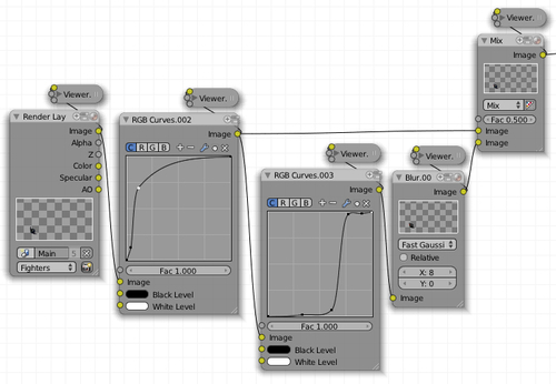
We're going to be running through several screenshots to describe the process. Since the composite setup is not-so-simple, we'll start by taking a look at the setup as a whole. Let's inspect this screenshot:

The general setup can be described this way:
There is only one input node (
renderlayernode, at the far left-hand side).There is only one output node (the
compositenode is usually the only output).In the middle we have four rows of processing and a final series of three nodes for mixing the results of the four rows of processing. Let's label these processing rows with the letters A, B, C, and D (top to bottom).
Note
Before starting the creation of the composite setup make sure to click on the button with the camera that is at the bottom right-hand side corner of the
renderlayernode; that way the image buffer will be created and the compositing nodes will have the information they need to work with.Notice that the small nodes put above some processing nodes are just Viewer nodes, used to inspect the result of the processing at that point. A Viewer node can be added by going to Add → Output → Viewer and it can be collapsed by clicking on the triangle on its top left.
Now that we have a general idea of how the setup must be constructed, let's start with row A:

This row serves the purpose of performing a wide blur of the image from the renderlayer. The first node is a Blur node (Add → Filter → Blur) that receives the output from the image slot in the renderlayer node; it performs a strong blurring on that image using the Fast Gaussian method and using the value of
70both for the X and Y size parameters; we can then see a series of RGB Curves nodes (Add → Color → RGB Curves), which in reality are just one single RGB Curves node, but separated here to show side by side the curve for each channel. You will see that the color and green channels are being pushed to be more bright; the red channel is being brightened up a bit only in the shadows; finally, the blue channel is being strongly pushed to become brighter. The connection between these nodes is the obvious: Output slot "image" of a node goes into input slot "image" of the next node in the row, from left to right.Row B appears as seen in the following screenshot:

In this row we find the same structure as in row A, but this time the blurring is not as strong (X and Y sizes are set to 60), and the blurring method is set to Cubic. The series of RGB Curves showing each channel for a single node of its type show that all the channels were brightened up, being the blue the one that received the strongest lift. Connection between nodes is again as trivial as for row A.
Rows A and B serve the purpose of creating the nebula look; a blueish nebula can be deduced from the strong pushing we made to that channel in both rows. The reason for using two rows of nodes with almost the same setup is because it introduces variation both in color and shape that's needed to break with the simple look that only one of these setups would produce. Though this nebula still looks quite basic, the stars we are going to add later will help it to look much better.
Examining row C we find a more complex setup:

The first node of this row is RGB Curves (Add → Color → RGB Curves), which performs a clamping on the color channel. With this clamping the dark gray colors below 70% of brightness become totally black; the other shades of gray are just evenly distributed from black to white. Next we find a couple of nodes performing a small blurring on the result from the clamping RGB Curves node and then mixing the clamped image with the blurred one. Notice that the mix node is set to use a Fac of 1.0 and the Screen method, which is generally used to add highlights. At the output of the mix node we can put a Viewer node (Add → Output → Viewer) and check how the blurring adds immediately the sense of glowing to the points that are going to be the stars of the nebula. Finally, the output of the mixing node goes through an RGB Curves node, here shown separated into three to show how the Color, Red and Green channels look, which performs some lifting of the brightness of the image by increasing the contrast of the shadows (stronger slope, in the bottom left-hand side) and also reduces the contrast to the bright parts a bit (softer slope, upper right-hand side). The lifting for the red and green channels causes the image buffer to become yellow tinted.
The last row of processing looks like this:

This row is the simplest one in this setup. It just performs a nice processing by the Glare node (Add → Filter → Glare) that receives the image from the renderlayer node and then does a very subtle lifting of the color channel with an RGB Curves node. But don't let the apparent simplicity of this row make you think it is irrelevant, because the glare node does the very important task of generating the streaks to get the nice looking effect of stars.
The glare node is a very powerful node, which performs various tasks; in this setup we just use it in the streaks mode, which does the exact job of generating those nice fading lines that we usually relate to stars. Since we want very polished streaks we select the quality to be high and set iterations to 5. The color modulation adds some variation to the streaks that resembles chromatic aberration; the mix and threshold values determine how much of the result will be combined with the input image buffer and which color values to take into account when generating the streaks. Finally we select how many streaks to generate, how much to rotate the streaks, and the fading factor for the streaks. It is highly recommended to put a viewer node on the output of this node, play a bit with the settings, and get some practice on how it works. To see the full size image buffer getting into a viewer node, enable Backdrop in the header of the Node Editor; the backdrop will show the image coming into any viewer node that gets selected.
Finally we need to mix all these rows of processing to get the nebula mixed with the stars. For that, we perform the mixing with three mix nodes, as seen in the next screenshot:

The mixing is very straightforward, the links coming from the left-hand side and getting into the mix nodes are in the order A, B, C, D, from top to bottom. Notice that all three nodes use the screen method to mix the image buffers coming in, and don't forget to set the right values for the mixing factor in each node (Fac parameter). The last mixing node connects directly into the composite node (the node receiving the image buffer we want to use as the final result of the composite).
To finish the creation of the nebula we need to save a file with the final result. An easy way to do that is to add a viewer node to the last mix node, go to the Image Editor that is at the bottom left-hand side of the Compositing screen we choose from the beginning and choose the Viewer Node entry from the list of available images (drop-down menu on the side of the Image menu); once the image is visible, click on Image → Save As and save the file in the folder of the project. It's important to save in OpenEXR format, since that will let us perform some final tweaks on the compositing of the main scene if needed. To select a different file format, look for the File Type drop-down menu, in the left-hand side column of the File Browser. Let's also save the blender file.
This part of the project gives a first look at the power of the compositor. We started by creating a very simple particles setup to get a few dots rendered. The real magic happened in the compositor, where we took these dots and converted them into a basic nebula, including some nice stars within it.
In this part of the project we saved an image in an exotic format called OpenEXR. The OpenEXR format is an image format that saves images using float values for each color channel of each pixel. Common image formats such as JPG or PNG only use a limited range of 0-255 for each channel of each pixel. Since float values are able to represent a much bigger range of different values than the 256 allowed by common image formats, a render saved in OpenEXR format better preserves all the finer details that the render engine produces when performing the calculations. Of course, OpenEXR images produce quite big file sizes compared to its low color-depth counterparts.
Since we have been working on separate scenes for each part of the project, for the final render we need to put everything together, that way it's easy to work on the compositing part of the project.
Start by adding a new scene to our file and name it
Main.Add a camera to the scene and name it
mainCamera, go to the Object tab in the Properties Editor, and set the values in the Transform panel as follows:Location: 6.49 X, 10.71 Y, 3.96 Z
Rotation: 73.38º X, 0º Y, 165.39º Z
Now that the camera is placed, go to the
Planetscene, select the planet sphere, and go to Object → Make Links → Objects to Scene → Main. Go back to the main scene, select the planet sphere and set its properties (Object tab, in the Properties Editor) as follows:Location: 10.31 X, -10.89 Y, 3.30 Z (Transform panel)
The rotation for the Z axis can be changed at will.
The next object to bring into the main scene is the main ship; go to the
Mother Shipscene, select the object of the detailed mother ship and link the object to the main scene by going to Object → Make Links → Objects to Scene → Main. Now is a good time to bring up the Properties sidebar (View → Properties) and make sure the dimensions of the model correspond to these: 5.26 X, 3.38 Y, 1.77 Z.If the dimensions of the mother ship are very different from the given values, scale it until it gets values closer to the indicated ones. The location and rotation of the mother ship must be left unchanged (they must be zero).
We still need one more object in our main scene: the space fighter. Let's go to the space fighter scene, select the object, and hit Ctrl + L → Objects to Scene → Main. Now go back to the main scene, select the space fighter and apply these values in the Transform panel (Object tab of the Properties Editor):
Location: 6.57 X, 7.53 Y, 2.55 Z
Rotation: 14.21º X, 50.65º Y, 150.75º Z
Scale: 0.089 for all X, Y, and Z
If we take a look at what the camera is seeing right now, we should see something resembling the original sketch that we started with.
At this point you must be wondering: Where is the energy shield for the mother ship? We left the shield for later because the shader for it needed to be tweaked according to what the compositing nodes allowed (and helped) us to do.
Note
Certainly, the work on the energy shield is similar to what we did while creating the mother ship, because the final result we're reproducing here doesn't show the different exploration paths and tests that can be done when actually working on the project from scratch. Anyway, talking about how some things depend on others and the way it affects the production flow is a very good thing to highlight, since that helps have a better idea of how the original process went.
Thankfully, the shield isn't hard to create.
Let's add a UV Sphere and set its rings and segments to 16. Then go to the Object tab in the Properties Editor and set the Transform properties as follows:
Location: 0.9 X, 0 Y, 0.53 Z
Rotation: 0º X, 90º Y, 0º Z
Scale: 1.82 X, 2.8 Y, 4.5 Z
Name the object as
shieldand go to the Material tab in the Properties Editor to start working on the material that will simulate the energy shield.Add a new material (the slot will be created automatically) and name it
energyShield. Set its properties as follows:Diffuse panel:
Color: 0 Red, 0.1 Green, 1 Blue
Intensity: 0
Specular panel:
Specular Shader Model: Blinn
Intensity: 0
Ramp: enabled
Hardness: 20
IOR: 4.1
The diffuse color will just give a strong blue as the basis for the shader; its intensity is set to
0since we're going to rely on transparency to achieve the effect of seeing the border of the shield. The settings for the specularity are just the common settings that we've been working with: Blinn shader model, to have more control on the specular spot and a low hardness to let the spot grow. The specular intensity is put to0because we're going to control it by using a texture.Now for the ramp (Specular panel):
Interpolation method: Ease (just below the IOR value)
First color stop:
Position: 0
Color: 1 Red, 0 Green, 0.37 Blue
Alpha: 0
Second color stop:
Position: 0.106
Color: 1 Red, 0 Green, 0.37 Blue
Alpha: 1
Third color stop (click on the Add button above the ramp):
Position: 0.84
Color: 0.1 Red, 0.16 Green, 0.52 Blue
Alpha: 1
Input: Result
Blend: Multiply
What we are controlling here is the color that will be shown at each point of the specular "disc"; the interpolation method works great to get nice blending for strong colors like the ones used in the ramp color stops. The three ramp color stops are just indicating that the very center of the specular disc will be blue, then will blend into a strong pink color and then fade completely as indicated by the alpha of the first color stop. The input setting is necessary for the ramp to mold correctly to the form of the specularity, no matter the angle between the camera and the light causing it.
Let's continue adjusting the shader settings:
Shading panel:
Emit: 0.2
Ambient: 0
Transparency panel: Enabled
Method: Raytrace
Alpha: 0.345
Fresnel: 3.6
Blend: 1.23
IOR: 1.05
At this step we're just enabling the transparency, so that the camera will be able to see the mother ship; the
raytracemethod is needed to have refraction, which we use just slightly (IOR bigger than 1.0). The alpha value works together with the Fresnel and Blend values to provide the border effect for the shield. Showing the border of the energy shield is important in this scene, because that gives a visual clue that what is surrounding the ship is the energy shield that protects it.Having done the basic setup for the shader, it's time to go and add the textures that will give the rich look to the shield.
Let's go to the Texture tab of the Properties Editor and add two textures.
The first texture is called
shieldDistortand must be set as follows:Type: Clouds
Clouds panel:
Color mode: Greyscale
Noise: Soft
Basis: Blender Original
Size: 0.15
Depth: 6
Influence panel:
Diffuse Color: Disabled
Geometry: Enable Warp
Warp: 0.02
These settings just create a simple clouds texture in grayscale and small in size, which will be used to apply some random distortion of the shape of the next texture. To activate the distortion effect we enable Warp and set its value to
0.02to get a very subtle effect.The second texture is called
shieldFXand corresponds to the main texture for the shield look; its settings are as follows:These settings are mostly results of a trial and error process; the important idea behind trial and error is using the Voronoi type of function, since it creates a nice-looking structured texture. The scaling (Size of 8) is needed to get the individual "tiles" of the texture to be of the right size for the dimensions of the shield object. Finally in the influence panel we activate the influence of this texture on the intensity value of the specularity, and set its influence mode to Add. Since the material's intensity value for the specularity is
0, this means the texture has absolute control of the specular intensity.Now is a good time to separate the objects into different layers so that the compositing part can process them independently; after that we'll add the lighting to each layer, and get ready to composite the final result.
The objects must be put into layers as follows (select each object and set its layer by going to the Relations panel, in the Object tab of the Properties Editor):
Planet: layer 1
Mother Ship: layer 2
Space Fighter: layer 3
Energy Shield: layer 4
The lighting rig will be a bit complex, but not difficult to create. Let's start adding lights in layer 1.
Go to layer 1 (then type "1") and add three lamps, with these settings:
Lamp 1:
Type: Point
Energy: 2
Color: 1.0 Red, 0.9 Green, 0.75 Blue
Location: 24.45 X, 15.1 Y, 13.9 Z
Lamp 2:
Type: Point
Energy: 0.2
Color: 0.75 Red, 0.85 Green, 1.0 Blue
Location: 13.35 X, 17.5 Y, 12.3 Z
Lamp 3:
Type: Hemi
Energy: 0.5
Color: 0.01 Red, 0.02 Green, 0.04 Blue
Rotation: 111.15º X, 1.19º Y, -128.87º Z
Lamp 1 will serve the purpose of being the main source of lighting for the scene; its yellowish color tries to mimic the kind of lighting coming from the sun. Lamp 2 is just a simple fill light with a very low energy value; its blueish tint serves as an indication of cold light coming from all around the space. Finally, we have lamp 3, which will act as a very uniform fill light (Hemi lights produce very flat lighting) and set it to a blueish tint. Since point lights don't take into account its rotation when lighting the scene, its values are not provided. Hemi lights don't take into account its location (thus not provided here), but they do care about rotation values, and so they are provided.
In layer 2 we will add two lamps:
Lamp 4:
Type: Area (Lamp panel)
Color: 0.1 Red, 0.04 Green, 0.01 Blue
Energy: 0.3
Distance: 25
Gamma: 0.45
This Layer Only: Enabled
Area Shape: Square (Area Shape panel)
Area Size: 10
Location: 6.85 X, -3.35 Y, 1.63 Z
Rotation: 72.5º X, 30.25º Y, 44.05º Z
Lamp 5:
Type: Hemi
Color: 0.74 Red, 0.9 Green, 1 Blue
Energy: 0.3
This Layer Only: Enabled
Location: 4.06 X, -9.05 Y, 5.15 Z
Rotation: 61.35º X, 16.26º Y, 15.45º Z
These two lamps are set to only light objects living in the same layer as they are, so they will provide lighting only for the mother ship (this doesn't mean that the mother ship will only be lit by these lights!). Lamp 4 provides a dim orange tint to the ship, to convey the idea of the planet's reflected light affecting the ship; the settings for the area of the lamp cause its lighting to be distributed, which will give a nice soft distribution of lighting; the gamma setting is used as a trick to lower the contrast of the lighting provided by this lamp. Lamp 5 is used as a simple fill light for the backside of the ship, again with a blueish tint, like all the fill lights in the scene. Notice that both lamps do care about the direction to which they are pointing, so their rotation values are provided.
Layer 3 will have no lights added and for layer 4 we have to work on creating the lights that will cause the energy shield to be shaded using the nice shader we created for it.
Start by adding a lamp with these settings (Object Data tab of the Properties Editor):
Lamp panel:
Type: Point
Color: 1 Red, 1 Green, 1 Blue
Energy: 3
Distance: 2.23
Sphere: Enabled
This Layer Only: Enabled
Location: 1.31 X, 2.76 Y, 2.45 Z
This light will only light the sphere shape around it, until the distance value is reached. Since this effect is only needed for the energy shield, we enabled the option to affect only objects in this layer. Now let's duplicate this light a couple times and put its duplicates at some other places near the shield object, to add some nice variation to the shield impact effect for each lamp. Make sure to change the distance setting, the energy, and to put the lights at different distances from the surface of the shield object. Strong changes in the energy value will also cause strong differences in the shield impact effect of each lamp.
For the left-hand side of the shield (looking from the camera) we want to add a bigger shield impact effect.
For that we need a different lamp than the ones we've been creating until now; these are the settings:
Type: Sun
Color: 1 Red, 1 Green, 1 Blue
Energy: 5
This Layer Only: Enabled
Location: 7.74 X, -0.14 Y, 0.42 Z
Rotation: 81.24º X, 74.47º Y, 23.02º Z
The reason for using a sun lamp is because it will cause the specularity on the shield to be bigger, making the effect bigger. The main reason for wanting to do that is to get a shield impact spot where it clearly shows the shape of the shield.
There is one last little step to do to make sure the shield is going to be affected only by these lamps.
Select all the lamps that we created to cause the shield impacts and go to Object → Groups → Create New Group. Now go to the Object tab in the Properties Editor, locate the Groups panel, and change the name of the group to
shieldImpact.Next, select the shield object, go to the Material tab in the Properties Editor, locate the Options panel, click on the Light Group field (shows an icon with a sphere and a cube) and select the
shieldImpactgroup; also enable the Exclusive option, so as not to let any other object be lit up by lamps in this group.Note
There's quite some redundancy here, since the lamps are controlled by the layer and distance + sphere options; but it's not a bad idea to make entirely sure that things will work as we need them to.
As a last step we're going to prepare some settings that will only be used for the Mother Ship, when compositing the scene.
Let's go to the Properties Editor, locate the World tab and set these options:
Ambient Occlusion panel: Disabled (it will be enabled later)
Factor: 1
Blend Mode: Multiply (drop-down menu)
Gather panel:
Gather Method: Raytrace (first row of options)
Attenuation Distance: 1
Attenuation Falloff: Enabled
Attenuation Falloff Strength: 0.01
Sampling Method: Adaptive QMC
Samples: 16
What we are doing here is preparing the settings for Ambient Occlusion, which is a nice method to add shadowing to the objects in the scene. Setting the Blend Mode to Multiply causes the shadowed parts to become quite dark, which is what we need. The Gather Attenuation options are for controlling how wide the shadows will be; since this effect will only be applied to the mother ship, we use a small distance (the details of the ship are quite small). The Raytrace method is the one with the best results in terms of shape of the shadows; the method and samples are set to get soft shadows (a low samples number will likely cause noise in the rendered shadows). Now, why leave these settings disabled? (Ambient Occlusion panel was left disabled), well, that's because this effect will only need to be applied for one layer of the scene, not for the whole scene, so we will come back and turn it on temporarily only when needed.
That's it for the scene creation; now it's time to play with the compositor.
We left for the very end the creation of the energy shield for the mother ship. This task requires no modeling, since we use a sphere with some scale values; the actual shield effect is achieved by means of the shaders. In this case we applied Raytraced transparency (to be able to use some slight refraction) and worked only on the specular shader for the material. The trick is about textures and ramps, and getting the effect of the textures affecting the right channels of the material. The lighting works together with the shading, and we just created a basic lighting setup to control where the impacts on the shield will be located.
We also prepared a simple Ambient Occlusion setup, in order to be ready for the compositing part of the final scene.
The compositing will be done in the same scene that we are working in, which is "Main". Before we do any node manipulation, we must separate the parts of the scene using RenderLayers; then we can go to the Node Editor and create the node setup to get our nice final render.
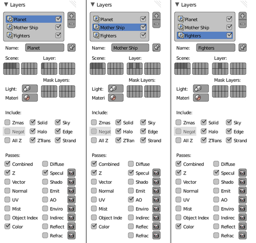
Start by going to the Render tab of the Properties Editor and locating the Layers panel. Change the name of the default renderlayer to Planet, locate the Layer buttons (Scene and Layer appear as two grids of buttons, as seen in the next screenshot) and enable layer 1; in the Passes section below, make sure to have Combined, Z, Color, and Specular enabled.
Add a second renderlayer, name it Mother Ship, enable layers 2 and 4 in the Layer buttons, and in the Passes section make sure to have Combined, Z, Color, Specular, and AO enabled.
The last renderlayer must be named Fighters, the Layer buttons must have only layer 3 enabled, and the enabled passes must be Combined, Z, Color, and Specular. This screenshot shows the setup for the three renderlayers:
Note
The passes other than Combined and Z won't be used explicitly in the compositing setup; the reason to enable them is just to have the possibility to inspect more closely a certain component of the image at any moment while working on the compositing setup.
To finish the renderlayers setup, make sure that layers 1, 2, 3, and 4 are enabled in the Scene buttons grid (to the left-hand side of the Layer buttons) in any of the renderlayers—it's a shared setting between all the renderlayers.
With all the renderlayers settings in place, it's time to do our magic with the Node Editor.
Go to the Compositing screen, choose the Compositing nodes option, and enable Use Nodes in the header.
This setup will be composed of four rows of processing nodes and a group of three mix nodes to join the separate results. The general view of the setup is as follows:

Let's call the processing rows A, B, C, and D (from top to bottom), and start with the close-up for row A:

We start by creating an Image node (Add → Input → Image) and loading the
.exrimage rendered previously in the Nebula scene. Then we proceed to add an RGB Curves node (Add → Color → RGB Curves) node and perform a standard lowering of brightness; the Scale node is only needed if the render size for the composite is smaller than theNebula.exrimage. Finally the translate node allows us to move the nebula image anywhere in the background.Now let's see the setup for row B:
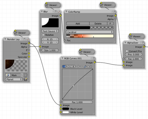
First we add a Render Layers (Add → Input → Render Layers) node, and pick the
Planetrenderlayer; to create the image buffer for this renderlayer, let's click on the camera icon in the bottom right-hand side of the node. In this screenshot we can see two processes being performed. The Blur and ColorRamp at the top are used to create a glowing effect for the border of the planet; notice that the Blur node input is not the image from the render layer, but its Alpha channel; the blurring creates a soft region of transition between the planet and the empty space around it, then the ColorRamp takes that grayscale image and maps it into a gradient.The color stops for the ColorRamp are as follows:
Color stop 1:
Color: 0 Red, 0 Green, 0 Blue
Position: Completely to the left
Alpha: 0
Color stop 2:
Color: 1 Red, 0.24 Green, 0.11 Blue
Position: Around 1/3 from left to right (there is no way to specify the position by a number)
Alpha: 1
Color stop 3:
Color: 1 Red, 0.93 Green, 0.69 Blue
Position: Around 60% from left to right
Alpha: 1
The ColorRamp works this way: For every pixel in the input image buffer, map it to the gradient, if the input pixel color is black, take the leftmost color and alpha from the gradient but if the input pixel color is white, take the rightmost color from the gradient. Any gray color in between gets mapped to the appropriate point within the gradient. Checking the result of the gradient with a Viewer node helps to visualize this process and understand it. Don't forget to set the Blend type to Cardinal, since it's important to get a smooth transition between colors.
The RGB Curves node in the bottom just performs a simple lifting of brightness (Color channel), to make the planet more visible and the AlphaOver node in the left just puts the glow behind the planet.
Row C must be set up as shown here:
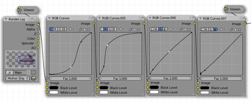
This is just a simple setup where we put a Render Layer node as input, selecting the
MotherShiprenderlayer and then perform a simple processing with an RGB Curves node, shown in the previous screenshot separated into four nodes, one for each channel.Note
Before clicking on the camera icon of the Render Layer node, be sure to enable Ambient Occlusion in the World tab of the Properties Editor. After the image buffer is created, remember to revert it to the disabled state.
The RGB Curves nodes perform these tasks: Enhance the contrast of the middle tones for all channels, increase the brightness of the dark tones of red, lift slightly the green channel, and finally, increase the contrast in a very small zone of the dark tones of blue. Since the last channel curve is too small to be seen clearly, let's have a closer look to better see what its shape is:

Notice the subtle shape of the curve at the bottom left-hand side.
The setup for row D is as follows:
The row starts with a Render Layer node, using the
Fightersrenderlayer. We then proceed to do a strong lifting of brightness in the first RGB Curves node in this row. A side processing of the image buffer performs a clamping of colors (both to the left and right) and then blurs the resulting clamped image. Finally we mix the result of the first RGB Curves node of this row with the result of the Blur node. The purpose here is to start brightening up the original image buffer (it's very dark) and then create a very high-contrast image to blur, to get nice blurred highlights in the space fighter. The final Mix node (Mix mode and 0.5 Fac) is just the standard way of mixing images when the only important thing is to mix colors.For the final mixing of the four rows of processing, we perform the mixing process:

Note that this time the mixing is performed using AlphaOver nodes. The reason for that is because we need to mix separate image buffers that have alpha channel information. There's also a small tweak to the overall brightness of the Red channel of the whole image buffer, using an RGB Curves node that feeds directly the Composite result node.
We separated the render process into renderlayers by associating one or more layers of the scene (Layer buttons grid) with a given renderlayer. The passes section determines which of the different kinds of calculations the render engine performs we want available as separate slots in the RenderLayer compositing nodes, when choosing a specific renderlayer. Activating the four layers in the Scene buttons grid is necessary, since the renderlayers are going to need to pick one or more of the layers selected there; it's like a two-step filtering: The Scene buttons grid decides which layers from the scene to feed into the render engine, while the Layer buttons grid picks from those layers the ones that will be used by a specific renderlayer.
And that's it! Our finished scene was created by modeling a mother ship and a space fighter, adding a bit of work in the shaders for the space fighter, then creating a background composed of a planet and a nebula background for which we did a bit of work with a particle system and the compositor. The final touches for the scene were done by adding the energy shield and performing the final composite on the full scene.
Let's take some time to look at our finished image:
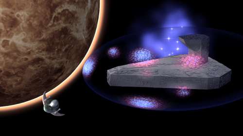
Our scene looks quite good, but it can definitely use some improvements, let's check a few of them:
How about giving the nebula a nicer look? Adding some texture to it will help a lot in enhancing the background.
What if there are more space fighters in the scene? Let's work on creating some duplicates of the space fighter and spread them all around the scene. Playing with their distances from the camera can help a lot in adding depth to the scene.
How about checking an image from a space movie and getting some info about the background color? That will give you some ideas on how to improve our very simple black background.
Adding detail to the mother ship could be of help to enhance its look: Big cannons and antennas are possible enhancements for it.
Our mother ship could be enriched very much by adding some effects that mimic light coming from it: Small windows, space ports on the sides, and the bridge could be created by adding a few simple 3D objects and playing on the compositor.