Download code from GitHub
Re-Coding a Basic Blinn-Phong Shader with Unity/CG
The art of shaders has always been known for being fairly complex. While a few math operations can easily simulate a flat 3D surface with some lighting and shadows, creating great and optimized visuals for your games can be a hard task. As a beginner, you can always copy-paste some script in the hope that it magically transforms your visuals, but to truly design your own style, you will need quite a lot of time to learn all the ins and outs. Still – shaders are definitely worth digging into, and nowadays, with engines such as Unity, we have an opportunity to discover more about this unique field step by step.
Shaders are how our computers are able to render 3D to 2D, and they are paramount to most modern video games: be it to actually show your 3D scene or to create catchy VFX to bring your world some life, they are a key element to creating visuals. Thanks to their parallel structure, they can also take advantage of our latest GPU-based architectures, and they are blazingly fast. All of this can take some getting used to, for sure; still, the results are pretty amazing once you manage to set everything up properly.
Need some refreshers on the fundamentals of shaders?
If you want to review some essentials on the structure of shaders, the vertex and fragment shader functions, and specific Unity semantics to feel more comfortable when tackling more advanced shading techniques in the upcoming chapters, you can have a look at the Appendix: Some Quick Refreshers on Shaders in Unity, at the end of the book!
So, before we dive into Unity’s newest shading tools and discover the more modern render pipelines, let’s get back into the swing of things with a practical example of how to design and implement a classical shading model: Blinn-Phong.
Although this model is somewhat old and has now mostly been replaced by physically-based rendering, it will be easier to wrap our heads around and discuss in this review chapter. It will also be a good opportunity to do some quick reminders about 3D lighting and about how to perform basic operations such as diffuse, ambient, and specular lighting.
So, in this chapter, we will review the basics of shader coding in Unity with the usual built-in pipeline in a hands-on example. It will take us through all the steps required to create a vertex-fragment shader, debug it, and implement a simple 3D lighting model. We will also learn a few tips for improving the user-friendliness of our material inspectors and better controlling how shader properties are exposed.
We will cover the following topics in this chapter:
- Doing a quick study of the Blinn-Phong shading model
- Setting up our shader in Unity
- Adding the ambient and specular components
- Making a top-notch inspector!
Technical requirements
To try out the samples yourself, you will need to have Unity installed (note that the examples in this chapter do not require any specific version). You will then need to create a project with the common 3D template.
You can find the code files for this chapter on GitHub at https://github.com/PacktPublishing/Become-a-Unity-Shaders-Guru/tree/main/Assets/Chapter%2001.
Doing a quick study of the Blinn-Phong shading model
Working with shaders can be tricky when you don’t know exactly what you are planning. Although skilled technical artists can get away with some shots in the dark and develop the logic of their shader as they implement it, it is often more reassuring to anticipate the computation and the composition of the different components your shader will use.
This process of listing the features your shader needs to have is what we call defining its shading model. It is crucial for beginners and often pretty useful for more advanced developers, too.
To understand what this step implies, we will define the Blinn-Phong shading model we want to implement here with an easy and well-known lighting model: the ambient/diffuse/specular model. We will first discuss the basic diffuse lighting, then see how to add ambient lighting, and finally dive into the specular lighting to understand how to implement all three of them in our shader.
Using diffuse lighting for a basic render
Diffuse lighting is often the first step to implementing any kind of lighting for your shader. It is the direct illumination of the object by the light, or in other words, the effect by which the surface re-emits some or all of the incoming light that hits it. The color of the object depends on which part of the light is absorbed and which part is re-emitted.
This lighting does not depend on the direction you are currently facing. It is how you can render a 3D matte surface, and it is usually what you think of when you’re asked to picture a 3D object floating about like this:
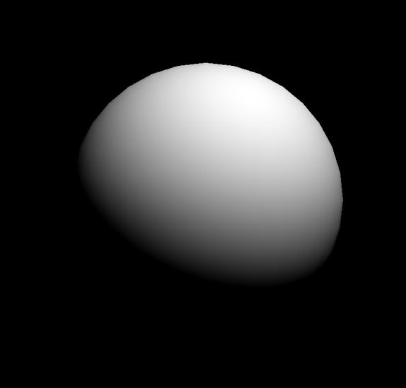
Figure 1.1 – A basic diffuse lighting of a 3D sphere
In the case of the Blinn-Phong model, we can compute this base surface brightness based on the position of our light source and the normal of said surface. Let’s consider a schematic visualization of this direct illumination of the surface:
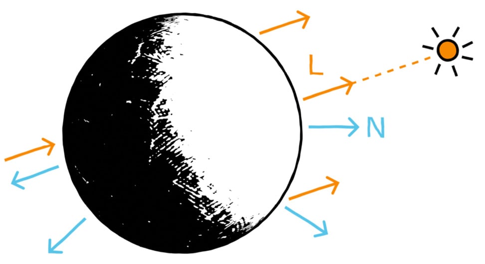
Figure 1.2 – Light vector (L) and normal vector (N), used to compute the diffuse lighting component
This diagram introduces two relevant vectors for the computation of the diffuse lighting:
- Light vector (
L): This is the direction from the surface to the light source. Since we are assuming a single directional light source that is infinitely far away, this vector will be the same for each pixel of the object. - Normal vector (
N): This is the outgoing direction from the surface that is orthogonal to its tangent plane.
Direction versus vector?
Throughout this section, we will define and use various vectors that are in all directions. This basically means that we are only interested in the line along which the vector spreads and which side the arrow points; the length of the vector, however, is ignored and considered normalized to 1.
We can see in Figure 1.2 that we want the diffuse component to be maximal when the surface is facing the light and minimal when it faces away from it. This can easily be computed by taking the dot product of the L and N vectors clamped to the [0, 1] range. This clamping can be done directly using the saturate function, which is common in shader languages.
Since this reflectance process is called the lambertian reflectance, this black-to-white mask is often called a lambertian (lambert), and we can express it as:
float lambert = saturate(dot(L, N));
Then, to take into account the color of the light source, lightColor, we need to multiply this value by the color variable (expressed as or cast to float3):
float3 diffuseLight = saturate(dot(L, N)) * lightColor.xyz;
Finally, to also consider the color of the object, color, we simply need to re-multiply our colored diffuse lighting by this other color (again, expressed as or cast to float3):
float3 diffuseColor = diffuseLight * color;
As we will see in the Setting up our shader in Unity section, if we implement this into our fragment shader function, then we will get something similar to Figure 1.1.
Now that we have seen how easy it is to compute the diffuse lighting, let’s see go ahead and see why ambient lighting can be a quick way to improve our lit shaders.
Better integrating the object – thanks to ambient lighting
The diffuse lighting, we just discussed is usually the first step to having your object exist in a render: it is a way to pull it out of the shadows by defining how light sources illuminate its surface. However, this first component can only go so far – in particular, the diffuse lighting is not aware of the surroundings of the object and the environment it is in.
This is why, usually, to help integrate your object into your scene, you also need to consider your environment’s ambient lighting.
Ambient light is a light that does not come from any specific source – it is everywhere in the scene and illuminates slightly all the objects from all around. In a nutshell, it is light with neither an origin nor a direction. It is the light that bounces around the environment, and that allows us to see our shapes in a 3D render even if there are no specific light sources, as shown in Figure 1.3:
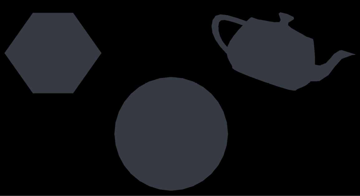
Figure 1.3 – Ambient lighting of a few random 3D shapes
It is also why, in real life, most of the time, even the side of an object that is in the shadows is not completely dark. Figure 1.4 shows the difference between a simple diffuse material without any ambient lighting and another that integrates this second component and therefore does not have a fully black side opposite the main light:
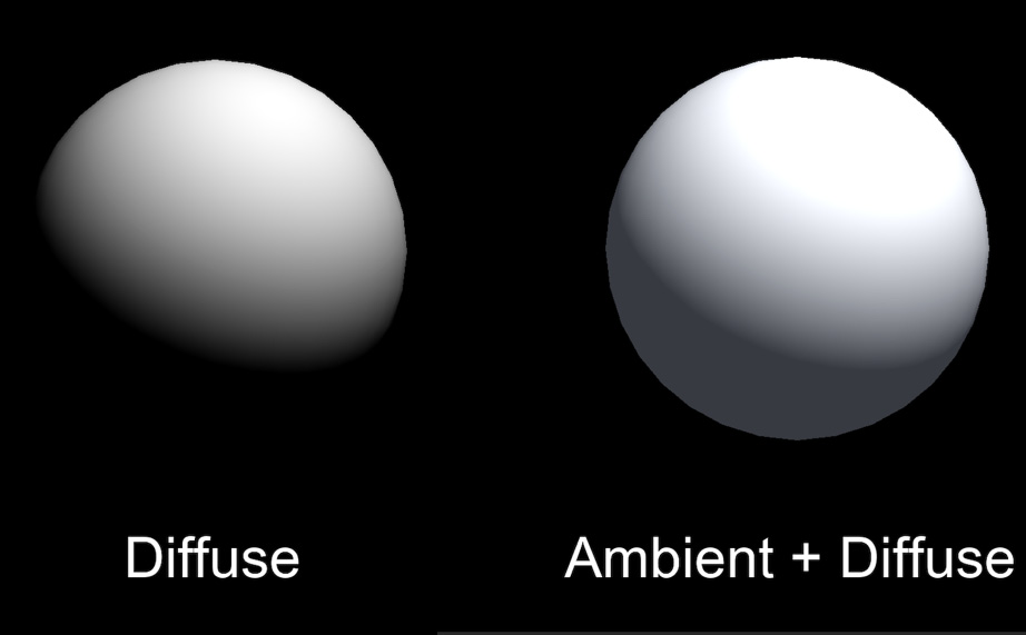
Figure 1.4 – Comparison between a shader with only a diffuse component and a shader with both the diffuse and ambient components
Ambient light is useful in many cases, most notably whenever you want to control the overall brightness of the scene without having to adjust each light individually. For example, if you want to bring out the colors of a cartoon style, ambient light can be a nice solution.
In all generality, the ambient light component is computed as a product of intensity and color:
float3 ambientLight = ambientIntensity * ambientColor;
Note that, this time, we shouldn’t multiply ambientLight by the color of the object because this ambient component is global to the scene and applies the same to all the shapes in the render. So, since we want this ambient lighting to be the minimum of the light that all objects in the scene get, we just need to add to our previous diffuse component to get the combination of both:
float3 diffuseAndAmbientColor = diffuseColor + ambientLight;
Of course, the tricky part can be to actually get the value of the ambientIntensity and ambientColor variables: depending on the software you use, this information can be more or less hidden inside the engine. However, we will see in the Adding the ambient and specular components section that in Unity, this data can be retrieved pretty easily inside of a shader code.
We are now up to speed with two light components out of three... finally, last but not least, let’s recall the fundamentals of specular lighting!
Adding some light reflections with a specular
Until this point, the diffuse and ambient components we discussed were fairly easy to describe, and, in particular, they did not depend on the position of the camera at all. No matter where you render your diffuse or ambient from, the result will always be the same.
Specular lighting, on the other hand, is different. It is what causes a shiny surface (typically a plastic or a metal) to have some bright spots, glossy edges, and lighter faces, like this:
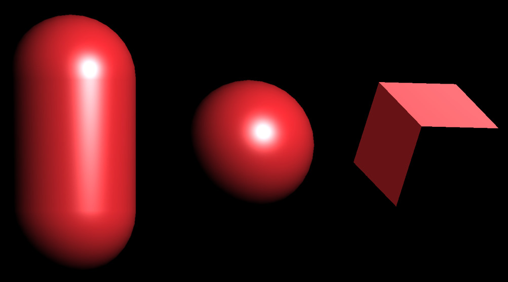
Figure 1.5 – Basic specular lighting of a capsule, a sphere, and a cube with a single directional light
Specular reflection is like a mirror reflection – if the surface is smooth enough, the incoming light rays are reflected toward the viewer’s eye and create those localized highlights. The specular component, therefore, depends on three vectors:
- The (normalized) normal vector of the surface,
N, as discussed for diffuse lighting - The direction from the surface to the light source,
L, as discussed for diffuse lighting - The direction from the surface to the camera is often called the view vector and is denoted as
V
And this is where we are finally going to talk about the “Blinn-Phong” we named our shader after! The Blinn-Phong reflection model is an improvement on the initial Phong model, both of which are methods for computing the speculars on a surface based on those three vectors.
The Phong model is more intuitive to understand; however, in practice, it is often less efficient and less realistic than the Blinn-Phong. This is why we are implementing the latter here. Still, to become familiar with how to compute the bright spots of a smooth surface in our render, let’s first quickly go through the Phong technique.
In short, the Phong reflection model tries to determine how close the V vector is and the exactly reflected light vector, R. Figure 1.6 shows this auxiliary variable, which is simply the outgoing ray of light after L has bounced off the surface:
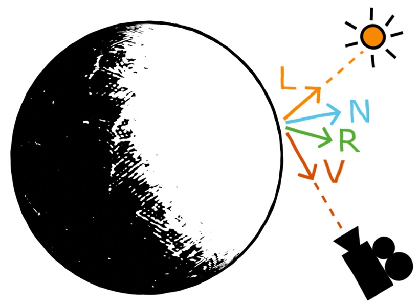
Figure 1.6 – Light vector (L), normal vector (N), view vector (V), and reflected light vector (R), used to compute the Phong specular lighting component
Once again, the High-Level Shader Language (HLSL) shaders have plenty of useful built-in functions for this type of operation. Here, for example, we can use the reflect function and give it in the incoming vector (meaning, our outgoing light vector, L, but reversed) and the normal vector, N, to reflect around:
float3 R = reflect(-L, N);
OK, so – the Phong model checks how close we are to looking directly at the light source in a mirror, with the mirror being our object’s surface. As in our diffuse computation, the “closeness” of two vectors is computed using a dot product. This leads to the following formula for Phong specular highlights:
float3 specularLight = saturate(dot(V, R));
If we implement this model and show only our specular component, we then get something resembling Figure 1.7:
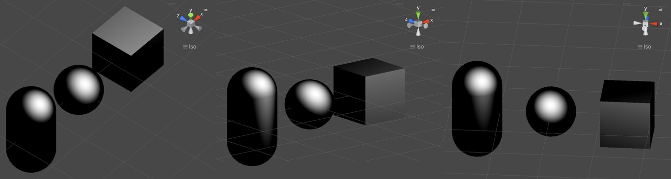
Figure 1.7 – Phong specular highlights on a capsule, a sphere, and a cube with a single directional light
As you can see in this screenshot, the specular does indeed depend on the position of the camera (you can look at the gizmo in the top-right corner to see the current view direction); however, it is not exactly the bright spot we were expecting.
This is because another important concept for specular lighting is the glossiness of the surface – although it is sometimes configured via its related opposite quantity, the roughness. The glossiness basically determines how smooth the surface is – if it is completely smooth, as a perfect mirror, then only a view vector perfectly aligned with the reflected light vector will show the specular. Conversely, if the surface has microfacets and tiny bumps, we will see specular highlights even if we are not looking at the surface in the exact direction of the reflected light vector.
Did you know?
The opposite of a perfect mirror surface, or in other words, a surface that makes specular highlights spread across the entire surface, is called a lambertian surface.
To apply a glossiness parameter to our specular computation, we need to use exponents. More precisely, we need to raise our specularLight variable to the power of our glossiness value, which here we can compute based on the normalized float value, _Gloss, as follows:
specularLight = pow(specularLight, _Gloss);
Because it is used as such, the gloss may also be called the specular exponent – but we will stick with the term “glossiness” here since this is way more common in game engines and 3D software.
Now, by tweaking this value, we can easily change the size of the specular highlighting to get a smooth or rough surface. Figure 1.8 shows various examples of increasing glossiness:
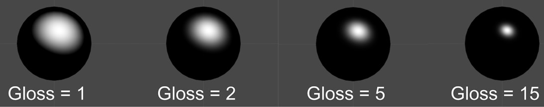
Figure 1.8 – Examples of Phong specular highlights for different values of glossiness
At this point, you might be thinking that we are done and that this Phong model is all we need to create specular lighting. Why would we need to step up to another Blinn-Phong model if this one already gives us these shiny spots and edges?
To really see the issue and why Phong is not as realistic a model as Blinn-Phong, you need to increase the glossiness of your shader to get small-sized specular highlights and have a look at one of the flat faces of the cube when the light is at a steep angle, such as in Figure 1.9:
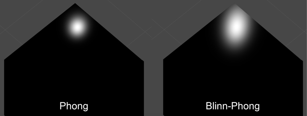
Figure 1.9 – Comparison of the specular highlight on a flat face with a light at a steep angle using a Phong or a Blinn-Phong model
Do you notice how Phong creates a fairly round spot while Blinn-Phong stretches the light on the surface along the direction of the light source, similar to what we have in real life? Phong gives us OK results for round surfaces, but as soon as you have a flat face, it will render way too close to a perfect mirror for most use cases. On the other hand, Blinn-Phong will create anisotropic speculars that are more realistic, which is why we usually switch over to this model in 3D rendering.
In reality, it is very easy to turn Phong into Blinn-Phong. The idea is that instead of computing the following:
float3 specularLight = saturate(dot(V, R));
We will instead calculate this:
float3 specularLight = saturate(dot(N, H));
Where H is the normalized average vector between V and the L light vector called the halfway vector (see Figure 1.10):
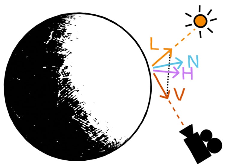
Figure 1.10 – Diagram of the vectors required to compute the Blinn-Phong specular lighting component
The result will be approximately the same, but it gives more realistic results, handles steep angles better, and avoids cutting off the light beyond certain angle limits, contrary to Phong.
To get our halfway vector, we can simply sum L and V and normalize the result. To sum up, the Blinn-Phong specular highlights can be computed with the following formulas:
float3 H = normalize(L + V);
float3 specularLight = saturate(dot(N, H));
specularLight = pow(specularLight, _Gloss);
With this implementation, there is, however, an edge case that can cause Blinn-Phong to get slightly off track – if your camera sees the surface at an extreme angle, up to the point that the light gets behind it, then there can be some small unrealistic remnant of light on the surface. This is because we don’t cull the light depending on whether it is behind the surface or not.
To fix this, we can simply use our lambertian from the diffuse lighting. Since, by definition, it is null when the surface does not face the light, we can simply multiply our specularLight variable by a check of the value of lambert, and only take into account the specular if the lambertian is not null:
float3 specularLight = saturate(dot(N, H)) * (lambert > 0);
Just like before for the diffuse component in the Using diffuse lighting for a basic render section, we can, of course, have these specular highlights be colored by the light source color by multiplying them together:
specularLight = specularLight * lightColor.xyz;
But the final question that needs answering is – how is this specular component composited with our two other components, the diffuse and the ambient lighting?
In short, we need to add this new component to the ones we computed before to mix together the previous shading result with these additional shiny spots:
float3 finalColor = diffuseAndAmbientColor + specularLight;
However, there is a little alternative that is interesting to point out. Let’s leave the ambient light aside for now since it depends on the environment and is a global setting. Then, in the previous formula, you’ll notice that the color of the light is taken into account, both in the diffuse and the specular components, but the color of the surface is only injected in the diffuse part. The specular highlights are currently not tinted by the color of the surface itself.
As a general rule, you want to leave the specular highlights as-is, as simple reflections of the light rays. But it can sometimes be interesting to also take the color of the surface into account if you want to (roughly) simulate metalness. Of course, this is a simplified model of a complex phenomenon, and if you need really realistic metal materials, you will probably have to leave Blinn-Phong behind and get into modern physically-based rendering. Still, as an approximation, this little trick of multiplying the specular highlights by the object’s color can create a metal-like feeling, compared to the unaltered speculars that remind us more of plastic, as shown in Figure 1.11:
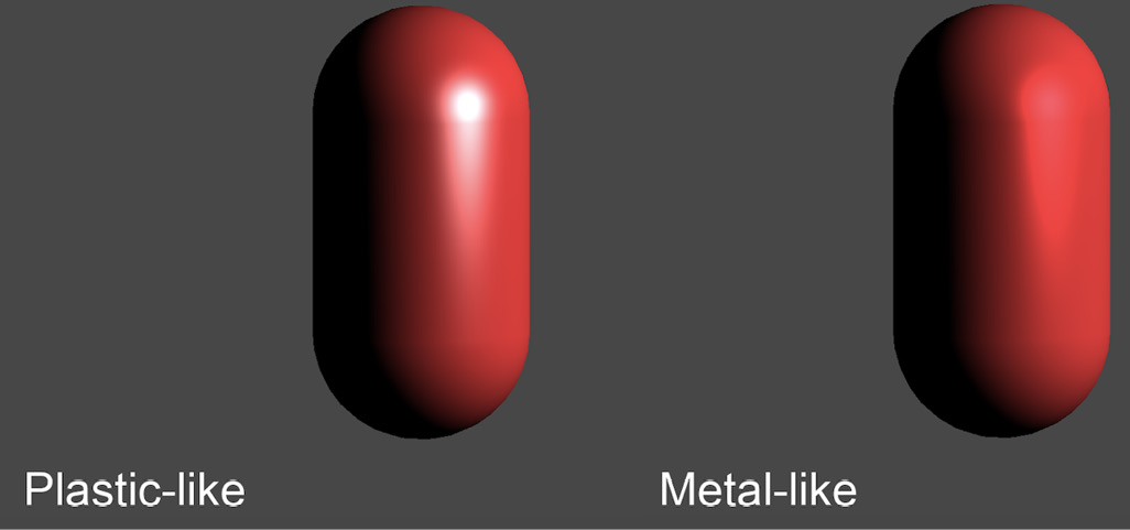
Figure 1.11 – Comparison of a specular model where highlights are not tinted by the surface color (plastic-like) and one where they are (metal-like)
This concludes our theoretical study of the Blinn-Phong shading model. We now have reviewed everything that is relevant to implementing this shader in Unity, so let’s see how to apply all of these formulas in practice!
Setting up our shader in Unity
With the Blinn-Phong model in mind, we are now ready to implement our shader with Unity’s legacy render pipeline.
The overall process will be to first create our shader and a matching material so that we can assign it to a 3D object in our scene, and then gradually add more and more components to properly re-create the diffuse component of the Blinn-Phong shading model we discussed in the Doing a quick study of the Blinn-Phong shading model section. Before we do anything, however, let’s quickly have a chat about the project requirements for this chapter so that you can test the samples yourself.
Checking your project configuration
Since we are using the built-in graphics here, you will need to create a new test project using the usual Unity 3D template. You can pick the template you want at the creation of your project, in the Unity Hub window, like this:
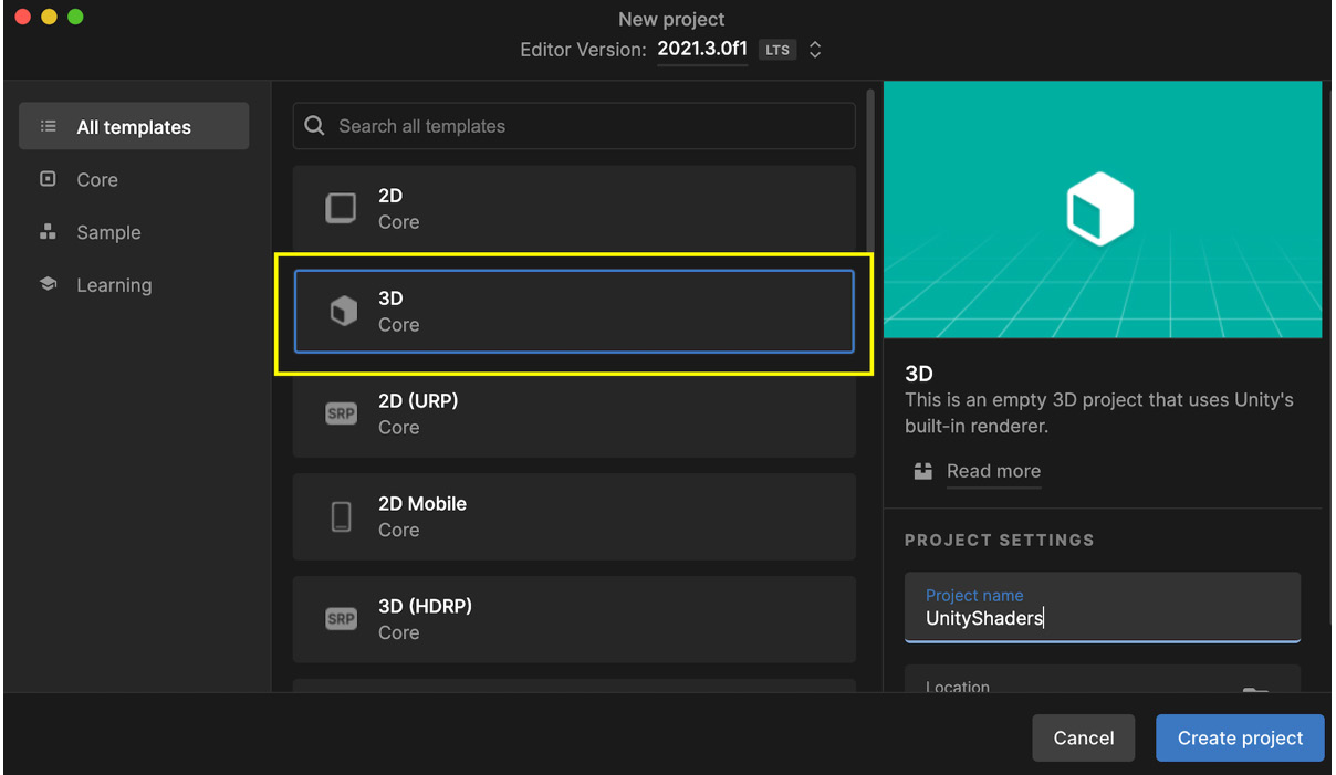
Figure 1.12 – Unity project creation panel in the Unity Hub with the 3D template highlighted
However, if you have already created a project using one of the newest render pipelines (Universal Render Pipeline (URP) or High Definition Render Pipeline (HDRP)), make sure to temporarily turn it off in your project settings if you want to use the shader we will make in this chapter. To do this, follow these steps:
- Go to the Edit | Project Settings... menu.
- Switch over to the Graphics section on the left.
- At the very top of the inspector panel, in the Scriptable Render Pipeline Settings slot, remove the asset reference (set it to None).
This will re-enable the built-in renderer and allow for our legacy shader example to work properly.
Creating the shader file
Time to start writing our Blinn-Phong shader! We will follow these steps to create the shader file:
- First, we will create a new shader asset in our project – to do this, simply right-click in the Project dock in your Unity editor and create a new shader file by navigating through the contextual menu (see Figure 1.13):
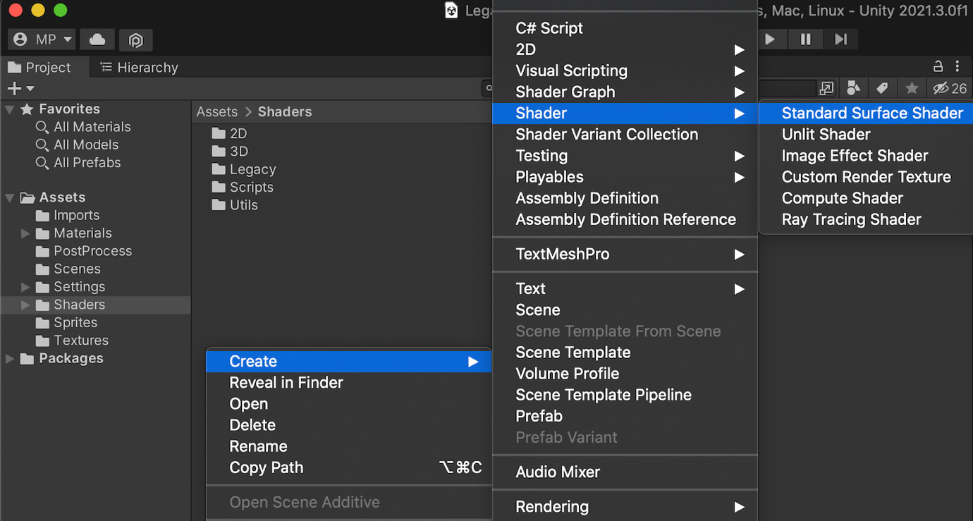
Figure 1.13 – Contextual menu for creating a legacy shader
You can choose whichever preset you prefer – we will remove almost all the auto-generated code to implement the shader from scratch, anyway.
- After you’ve created the asset, double-click on it to open it in an IDE. Unity will have filled the file with a basic shader based on the preset you chose. But to really understand what we are doing, let’s clear this and remove everything except for the top-level enclosing brackets with the name of our shader – your file should now look like this:
Shader "Custom/BlinnPhong"
{}
Defining the name and category of your shader
The first line in our shader file defines the unique reference of our shader as a path. Every forward slash in this quoted string corresponds to a level in the shader menu that unfolds in a drop-down list in the inspector panel when you pick the shader of a material. You can, of course, adjust it to your liking to organize the shaders differently in your project.
- Then, go back to the Unity editor. You will notice that your shader is recompiled automatically. By right-clicking on your shader asset in the Project window, you will be able to create a material that uses this specific shader with the contextual menu:
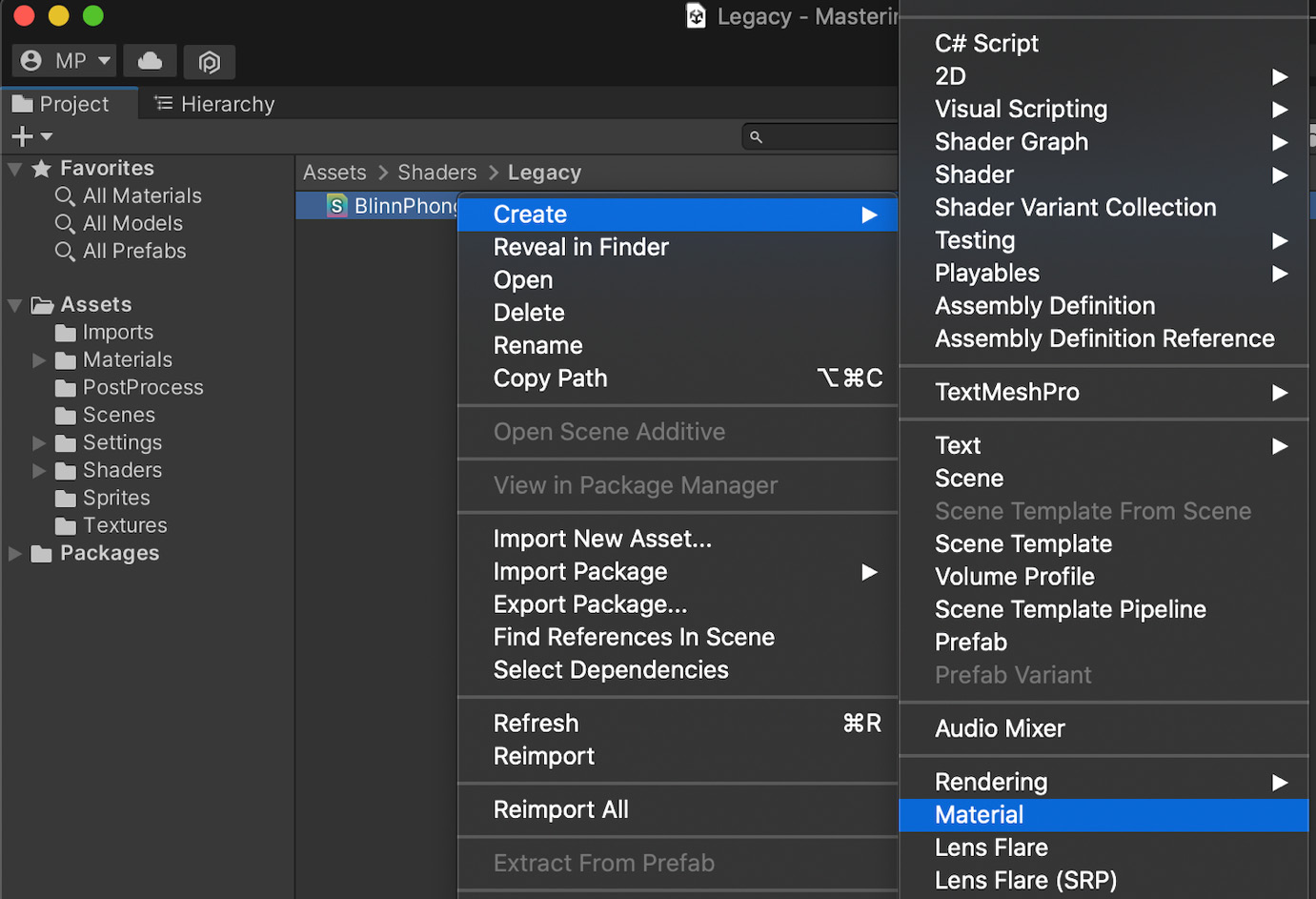
Figure 1.14 – Contextual menu for creating a material from a shader
- To finish setting up the test project, you need to add a 3D object (for example, a primitive sphere or a capsule) to your current Unity scene and assign it the material you created. Since this shader code is invalid, you will notice that the object appears in a magnificent flashy pink, as in Figure 1.15:
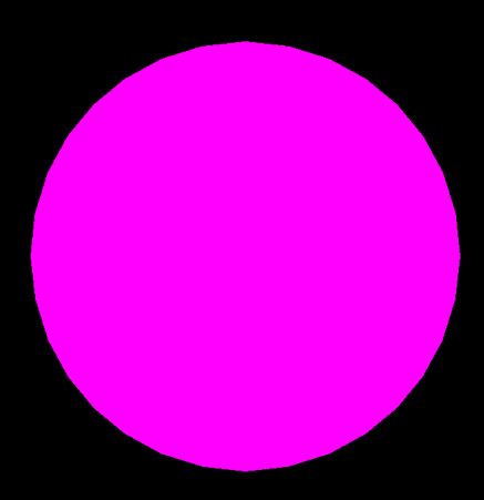
Figure 1.15 – Debug display of an invalid Unity shader
Even if it doesn’t look right, it does verify that our shader asset is indeed used for the object’s in-game render. But now, we should obviously fix our shader and turn it into a real Blinn-Phong!
The very first component we will implement will be the diffuse lighting. As we saw in the Doing a quick study of the Blinn-Phong shading model section, this requires that we define a color for our object and that we get the normal of our vertices to compute the diffuse contribution for the corresponding pixel.
The first step is to prepare the structure of our shader and, in particular, a property for our object color:
- To begin with, let’s declare a new
_Colorproperty for our shader and give it a default value of(1, 1, 1, 1), or in other words, pure white:Shader "Custom/BlinnPhong" { Properties { _Color ("Color", Color) = (1, 1, 1, 1) } } - Next, we will add our
SubShaderandPassblocks with a basic tag to specify that our shader is meant to be rendered as opaque:Shader "Custom/BlinnPhong" { Properties { _Color ("Color", Color) = (1, 1, 1, 1) } SubShader { Tags { "RenderType" = "Opaque" } Pass {} } }
At this point, we have recomposed our famous ShaderLab nested structure, and all that is left to do is fill the Pass block with our low-level shader code. For now, this code will be fairly simple – we will define very basic appdata and v2f structures, have our vertex shader code pass along the data unchanged, and make the fragment shader output our color directly, such as for an unlit shader. We will follow these steps:
- First of all, let’s add the CG start and end instructions, the pragmas to identify our vertex and fragment shader functions in the script, the usual inclusion of the
UnityCG.cginclibrary, and the declaration of the low-level_Colorvariable to match our exposed property:Pass { CGPROGRAM #pragma vertex vert #pragma fragment frag #include "UnityCG.cginc" float4 _Color; ENDCG } - Then, let’s define our simple
appdataandv2fstructures. For the time being, we will simply use the position of the vertices, so each structure will have a singlefloat4field with thePOSITIONorSV_POSITIONsemantic:Pass { CGPROGRAM ... struct appdata { float4 vertex : POSITION; }; struct v2f { float4 vertex : SV_POSITION; }; ENDCG } - Our data is now ready to be used as input or output by our
vertvertex shader function. We just have to convert our incoming vertex 3D position into the equivalent 2D position in clip-space, thanks to Unity’s built-inUnityObjectToClipPosfunction, like this:Pass { CGPROGRAM ... v2f vert (appdata v) { v2f o; o.vertex = UnityObjectToClipPos(v.vertex); return o; } ENDCG } - And finally, we can create a one-line fragment shader function,
frag, that simply returns the color we defined for each pixel of our object:Pass { CGPROGRAM ... float4 frag (v2f i) : SV_Target { return _Color; } ENDCG }
You can now come back to the Unity editor, let the shader recompile, and admire your brand-new white shape in the Game view. At this point, we have made a basic unlit shader with Unity’s built-in rendering pipeline that we can adjust the color of by tweaking the Color property exposed in the material’s inspector, as shown in this screenshot:
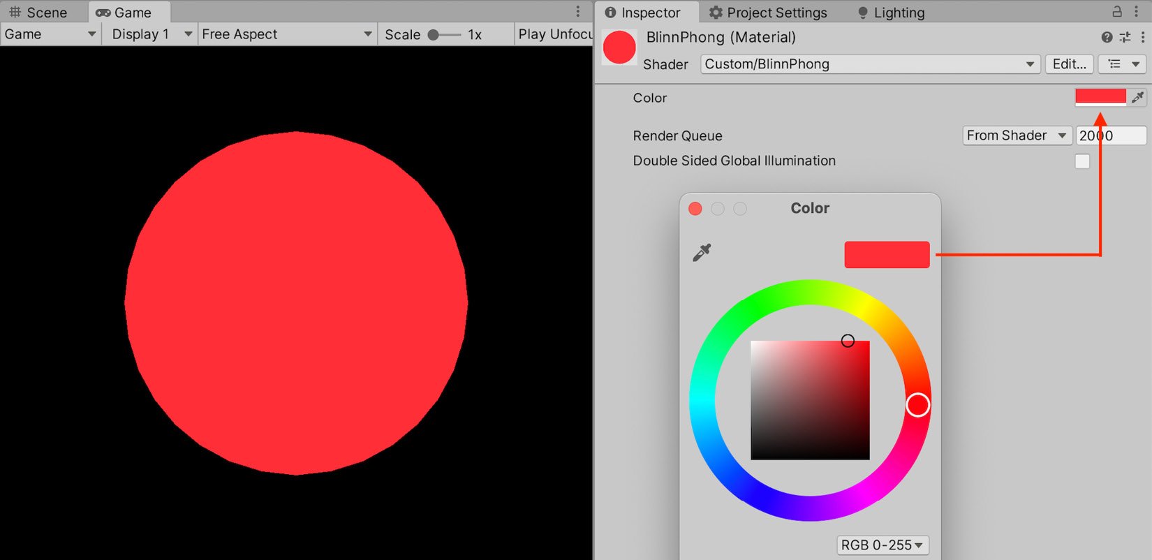
Figure 1.16 – Simple unlit shader with a color property that can be set in the inspector
The next step is to modify our unlit shader to compute some diffuse lighting.
Implementing the diffuse lighting
All right, at this point, we have a basic shader structure that allows us to render our object as unlit. But, of course, this is not what we want! It is time to draw from our previous reminders on diffuse lighting.
In the Doing a quick study of the Blinn-Phong shading model section, we saw that our diffuse component could be computed based on the normal of the N surface and its direction to the light, L. Let’s go through each of those vectors one by one and see how we can calculate them in Unity!
First of all, the normal is easy enough to get. We can simply ask Unity to pass it in our input vertex data structure by adding a float3 field with the NORMAL semantic, like this:
struct appdata {
    float4 vertex : POSITION;
    float3 normal : NORMAL;
};
Then, we have to transfer it over to the output data structure in our vertex shader function. The interpolators don’t support the NORMAL semantic in the same way – instead, we have to store this data in our first UV set denoted by the TEXCOORD0 semantic. Then, in our vert function, we need to use another Unity built-in function to convert the normal from the object space to the world space, UnityObjectToWorldNormal, as follows:
struct v2f {
    float4 vertex : SV_POSITION;
    float3 normal : TEXCOORD0;
};
v2f vert (appdata v) {
    v2f o;
    o.vertex = UnityObjectToClipPos(v.vertex);
    o.normal = UnityObjectToWorldNormal(v.normal);
    return o;
}
And finally, we retrieve it in the fragment shader from our interpolated data, and we apply the normalization step to get our N vector:
float4 frag (v2f i) : SV_Target {
    // get normalized normal for fragment
    float3 N = normalize(i.normal);
    return _Color;
}
A quick note on normalization
Even though the per-vertex normals Unity gives us in the appdata input data structure are normalized, we do need to ensure that the normal we get in our fragment shader is normalized too. This is because, since it’s interpolated, there is no guarantee that this blended normal actually has a length of 1. Although it will not cause any visual issues for the diffuse lighting, you will notice a disturbing faceting with the specular highlights if you forget to re-normalize this vector before the computations.
Next up, we will get our L vector. Remember that this is the direction from the surface to the light source and that, here, we are assuming there is only one main directional light.
Luckily, this is very easy to get in Unity – the engine directly offers us a built-in float4 variable called _WorldSpaceLightPos0 that contains the direction of directional light or the position of a spot or point light. The fourth component is either 0 if the light is directional or 1 if the light is not directional. So, in our case, we just have to extract the first three components of this vector with the usual HLSL swizzling to get our L vector:
float4 frag (v2f i) : SV_Target {
    // get normalized normal for fragment
    float3 N = normalize(i.normal);
    // get (outgoing) light vector
    float3 L = _WorldSpaceLightPos0.xyz;
    return _Color;
}
We now have everything we need to compute our lambertian reflectance, using the formula from the Doing a quick study of the Blinn-Phong shading model section:
float4 frag (v2f i) : SV_Target {
    // get normalized normal for fragment
    float3 N = normalize(i.normal);
    // get (outgoing) light vector
    float3 L = _WorldSpaceLightPos0.xyz;
    // diffuse lighting (Lambert)
    float lambert = saturate(dot(N, L));
    return float4(lambert * _Color.xyz, 1);
}
At this point, if you come back to the Unity editor and wait for the shader to recompile, you’ll have a shader that handles diffuse lighting and takes into account the color of the object, specified by the _Color property as we defined in step 1 of our structure definition in the Creating the shader file section. For example, if you set the color to gold-yellow, you will get something similar to Figure 1.17:
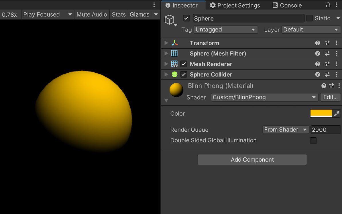
Figure 1.17 – Diffuse shader with a color property for the surface
To wrap up our implementation of the diffuse lighting, we should also make sure to get the color of the light into the mix. For now, you’ll notice that if you try to change the color of the directional light in your scene, nothing happens – the object still appears yellow.
The solution here is to include the UnityLightingCommon.cginc library so that we can access its _LightColor0 variable and multiply it with our lambert variable:
{
    #include "UnityLightingCommon.cginc"
    ...
    float4 frag (v2f i) : SV_Target {
        float3 N = normalize(i.normal);
        float3 L = _WorldSpaceLightPos0.xyz;
        float lambert = saturate(dot(N, L));
        float3 diffuseLight = lambert * _LightColor0.xyz;
        return float4(diffuseLight * _Color, 1);
    }
}
And here we are! If you try to change the color of either the object or the light, you’ll see that now they both impact the final color of the pixels in the render with the same additive mix as we experience in real life. Figure 1.18 shows how the same white sphere (meaning, with a _Color property equal to full white) results in different colors depending on the color of the light:
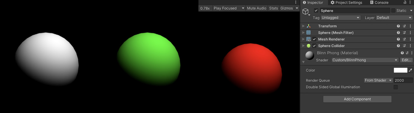
Figure 1.18 – Examples of renders with a constant white surface for the sphere but a changing light color
With that first component implemented in our Blinn-Phong shader, let’s move on to the two others: the ambient and specular lighting!
Adding the ambient and specular components
Our shader now handles the diffuse lighting. However, we know that this is just part of a real Blinn-Phong model – we also need to have some specular reflections, and we should handle ambient lighting to better integrate it into the scene.
In the following sections, we will add both components one by one, starting with the ambient lighting since, as we will see, it is quick to do in Unity before taking care of the speculars.
Injecting the ambient lighting
Do you remember how, in the Setting up our Unity shader section, we managed to get our light direction just by calling a Unity built-in variable? Well, guess what – adding ambient lighting is just easy!
All we have to do for this step is get the UNITY_LIGHTMODEL_AMBIENT variable, and this will directly give us the ambient light to add to our previously computed diffuse component, which means we simply have to update our fragment shader function like this:
float4 frag (v2f i) : SV_Target {
    float3 N = normalize(i.normal);
    float3 L = _WorldSpaceLightPos0.xyz;
    float lambert = saturate(dot(N, L));
    float3 diffuseLight = lambert * _LightColor0.xyz;
    float3 ambientLight = UNITY_LIGHTMODEL_AMBIENT.xyz;
    return float4(diffuseLight * _Color + ambientLight, 1);
}
And with these quick modifications, we added ambient lighting to our diffuse shader. If you recompile the file, you should see that the shape is now slightly illuminated everywhere:
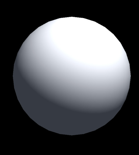
Figure 1.19 – Compositing of the diffuse and ambient lighting components
If you want to change the color of the ambient light, you can change this in the environment parameters of the scene. These settings are located in the Lighting window. To access them, follow these steps:
- Go to the Window | Rendering | Lighting menu.
- Switch over to the Environment tab at the top of the Lighting window.
- In the inspector, you will see the ambient lighting in the Environment Lighting group.
Unity offers us three ways of setting the ambient color – either with a single source color, a gradient, or a skybox, which are discussed here:
- If you use the Color mode, then all ambient light will have the flat color you define in the color picker, as shown in Figure 1.20:
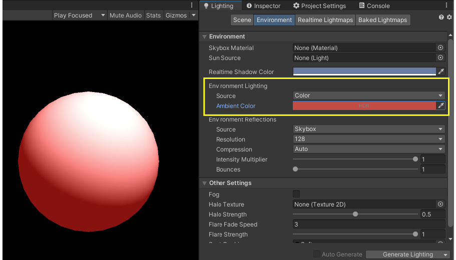
Figure 1.20 – Configuration of the ambient color for the Unity scene in the Color mode
- If you use the Gradient mode, you will be able to define separate colors for ambient lighting coming from the sky, the horizon, and the ground. You will have three pickers for each of those important marks, as shown in Figure 1.21, and the rest of the levels will blend between those references:
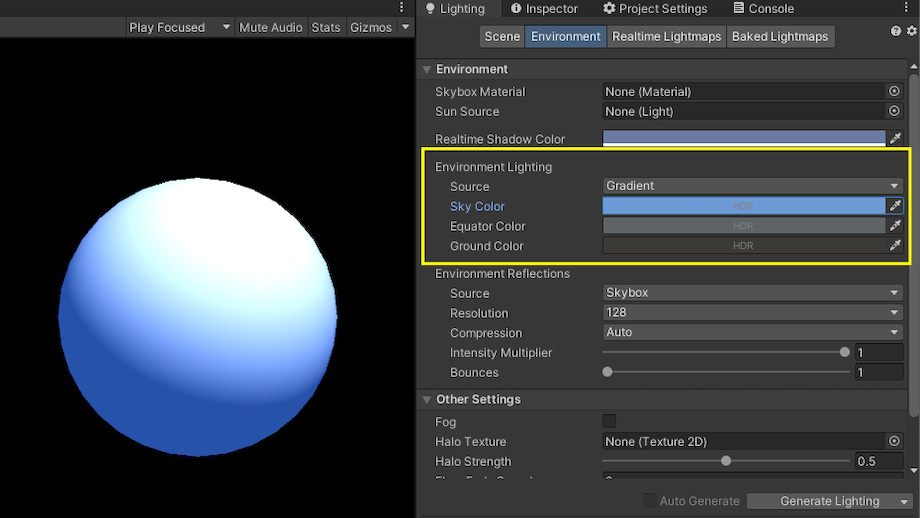
Figure 1.21 – Configuration of the ambient color for the Unity scene in the Gradient mode
Note that if you use Gradient, our UNITY_LIGHTMODEL_AMBIENT variable will use the sky color by default. But you can use one of the three defined color marks by replacing UNITY_LIGHTMODEL_AMBIENT with unity_AmbientSky, unity_AmbientEquator, or unity_AmbientGround.
- If you use the Skybox mode, then the ambient light will be computed based on the Skybox Material resource you pass in. This can help do more detailed lighting, but it requires a bit more setup. If you want to learn more about this, check out this documentation page from Unity at https://docs.unity3d.com/Manual/skyboxes-using.html.
We now have a shader with both the diffuse and ambient components, and we even know how to change the color of our ambient light to create a custom feel for our scene. However, this material is visually quite basic and very matte – so it is time to implement the final part of our shader: the specular.
Computing the specular lighting
As we discussed in the Doing a quick study of the Blinn-Phong shading model section, the only additional vector we need to prepare for computing the specular highlights with the Blinn-Phong reflection model is the view vector, V.
Remember that this is a vector that goes from the surface to the rendering eye position. To compute it, we therefore need to get the position of our main camera and the position of the fragment we are currently calculating the output value for, both in world space coordinates.
As usual, the camera position is readily available in the UnityCG.cging library. The _WorldSpaceCameraPos variable directly gives us the 3D world position of the main camera.
The world position of the vertices can be found using the vertex position in object space and the handy unity_ObjectToWorld matrix. Multiplying this matrix by the local vertex position converts the local coordinates to world coordinates and gives us its equivalent as a world position. We then simply need to pass it in the v2f data structure as our second UV set to have it interpolated and re-inputted into the fragment shader. Here are the updated parts of our shader code:
struct v2f {
    float4 vertex : SV_POSITION;
    float3 normal : TEXCOORD0;
    float3 worldPos : TEXCOORD1;
};
v2f vert (appdata v) {
    v2f o;
    o.vertex = UnityObjectToClipPos(v.vertex);
    o.normal = v.normal;
    o.worldPos = mul(unity_ObjectToWorld, v.vertex);
    return o;
}
float4 frag (v2f i) : SV_Target {
    float3 V = normalize(_WorldSpaceCameraPos –
        i.worldPos);
    ...
}
Here, we use the normalize function to transform our position offset into a direction.
Then, we will define our _Gloss property for the surface smoothness:
Shader "Custom/BlinnPhong" {
    Properties {
        ...
        _Gloss ("Gloss", Float) = 1
    }
    SubShader {
        Tags { "RenderType" = "Opaque" }
        Pass {
            ...
            float _Gloss;
        }
    }
}
Finally, we simply need to copy back the formulas we prepared during the theoretical analysis to first get the halfway vector, H, get the specular, apply glossiness, and use the light source color. We eventually composite all three components in the final return with a simple sum. Our following fragment shader function, therefore, looks as follows:
float4 frag (v2f i) : SV_Target {
    float3 N = normalize(i.normal);
    float3 L = _WorldSpaceLightPos0.xyz;
    float3 V = normalize(_WorldSpaceCameraPos –
        i.worldPos);
    // diffuse lighting (lambertian)
    float lambert = saturate(dot(N, L));
    float3 diffuseLight = lambert * _LightColor0.xyz;
    float3 diffuseColor = diffuseLight * _Color;
    // ambient lighting (direct from Unity settings)
    float3 ambientLight = UNITY_LIGHTMODEL_AMBIENT.xyz;
    // specular lighting (Blinn-Phong)
    float3 H = normalize(L + V);
    float3 specularLight = saturate(dot(N, H)) *
        (lambert > 0);
    specularLight = pow(specularLight, _Gloss) *
        _LightColor0.xyz;
    return float4(diffuseColor + ambientLight +
        specularLight, 1);
}
At the very top, we get the three vectors we require for the diffuse and specular lighting, then we compute each component, and finally, we composite them. The following diagram shows how different primitive objects look with our associated material applied to them:
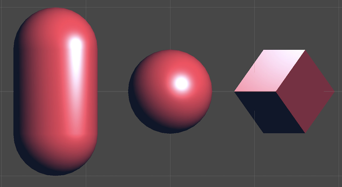
Figure 1.22 – Some applications of our final shader with the diffuse, ambient, and specular lighting components
We have successfully implemented the model we wanted with the following components:
- The diffuse component uses the color of the surface and the light to create a base lighting that is the same no matter where the camera is
- The ambient component slightly impacts all the shapes in the render and brings out the shadows
- The specular component varies depending on the position of the rendering camera, and it simply reflects the color of the light to make this shiny plastic-like effect
There are, of course, an infinite number of ways to tweak and modify all of our settings and simulate other types of materials. Even if Blinn-Phong is a crude lighting model, we know that changing the size of the specular highlights or tinting them with the surface color can already give quite a different feel, and we also said that ambient lighting is optional.
So, to further improve this shader, let’s take a bit of time to review Unity’s tool for creating easy-to-use and well-controlled material inspectors.
Making a top-notch inspector!
Now that we have an example shader to test things on, we have an opportunity to quickly discuss why creating an adapted inspector is important and how to do it. The following sections will explore both of these questions.
Why should I waste time refining an editor inspector?
This is probably a question that popped into your mind if you are not yet used to customizing or creating your own tooling in Unity, and it is a valid inquiry. Given that we’re talking about in-editor displays, who cares if it is a little messy? It won’t impact the quality of the final game!
Well, yes... and no.
It is true that, from a very objective standpoint, the look and feel of your editor interfaces doesn’t directly translate to the ones in your game. Your desk may be untidy, and still, you create amazing drawings.
However, generally speaking, it does hinder your productivity. If your interfaces are not properly designed, finding the right tool at the right time can quickly turn into a treasure hunt – it would be just like a messy in-game UI where players don’t know where to read their health points or where is the information on their current target.
This is even more true with these editor tools actually since the people who use them, your artist teammates or clients, expect them to be work tools. They are not here to have fun and be lenient about a few errors here and there. They want to get to their goal swiftly and without any headaches, so it is crucial that your tools guide them. In particular, your tools should relieve your users of thinking about how to use the interface... they probably already have enough thinking about what they want to make with it!
Your editor tools should thus be clear and, when applicable, aware of the context. In other words, they should possess the following attributes:
- Clarity: A Unity editor tool should not require you to read hundreds of pages in a manual to understand how it works. You should be able to quickly understand what variables you are changing and how they impact the final result just by looking at the interface and trying it out a few times.
Note that this also means tools should usually be quite focused – don’t try to create ultimate swiss-knives that can do everything because those will most probably confuse your users. Instead, narrow down the specific task you want to help them with, or at the very least break down the interfaces into multiple parts for each important subtask, which brings us to our next point.
- Context-awareness: When building a Unity editor tool, you have an amazing advantage compared to someone who makes real-world drills or screwdrivers – your interface can adapt dynamically! This can be via the use of tabs or sections or even with an auto-generation of a different layout based on what is currently selected, the preferences of the users, and so on. This is key in presenting all the information you want to the user in a readable manner.
If your tool is supposed to cover a variety of use cases, always try your best not to flood your users with too much data and take advantage of these context-adapted layout mechanics. Otherwise, the users will end up throwing away your tool before they understand all of its power.
This may seem like it is a bit of overkill in our case – after all, we just want to show some variables in an inspector to better configure our shader, right?
However, there are numerous ways of displaying those variables, and some will instinctively feel more in sync with the way they actually behave behind the scenes. So, time to dive in and see some easy examples of how to guide users who are discovering our shader via the interface!
Faking Booleans?
To begin with, we can look at a simple option in our shader – whether or not we should use ambient lighting. We’ve said that there are many cases where this is useful, but there are still other examples where you could want your shadows to be really dark and mysterious.
Ideally, this option should be available as a toggle with an on/off value, like a Boolean variable. However, we know that shaders cannot use Boolean variables – this is why, rather, we need to use Unity’s additional ShaderLab attributes to adapt our interface and fake these discrete values.
First of all, we will implement the logic. We just need to add an _UseAmbient float property and then check its value to use or ignore the ambientLight value, as we did in the Doing a quick study of the Blinn-Phong shading model section, with the lambertian to cut off the unwanted specular highlights:
Shader "Custom/BlinnPhong" {
    Properties {
        ...
        _UseAmbient ("Use Ambient", Float) = 1
    }
    SubShader {
        Tags { "RenderType" = "Opaque" }
        Pass {
            ...
            float _UseAmbient;
            float4 frag (v2f i) : SV_Target {
                ...
                // ambient lighting (direct from Unity
                   settings)
                float3 ambientLight =
                    UNITY_LIGHTMODEL_AMBIENT.xyz;
                ambientLight = ambientLight *
                    (_UseAmbient > 0);
                ...
            }
        }
    }
}
In this code snippet, I used a float variable for _UseAmbient and then checked whether it is strictly positive to use it as a Boolean in my computation. From a logical point of view, this trick solves our issue and hides the fact that this was initially a float. However, in the UI... we get a number input that accepts any values! Figure 1.24 shows how, for a random negative value, we do have the toggling of the ambient light, but we also have a very unintuitive interface:
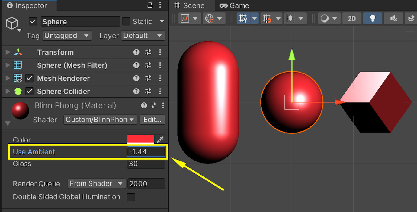
Figure 1.23 – Default display of a float input as a free value
To turn it into a checkbox and make it more straightforward to use, we’ll just go back to our shader code and, at the very top, add a [Toggle] attribute to our _UseAmbient property:
[Toggle] _UseAmbient ("Use Ambient", Float) = 1
This means that this float variable, although it could technically still take an infinite number of values, will only be editable via an on/off toggle in the inspector (and thus take the values 0 or 1), like this:
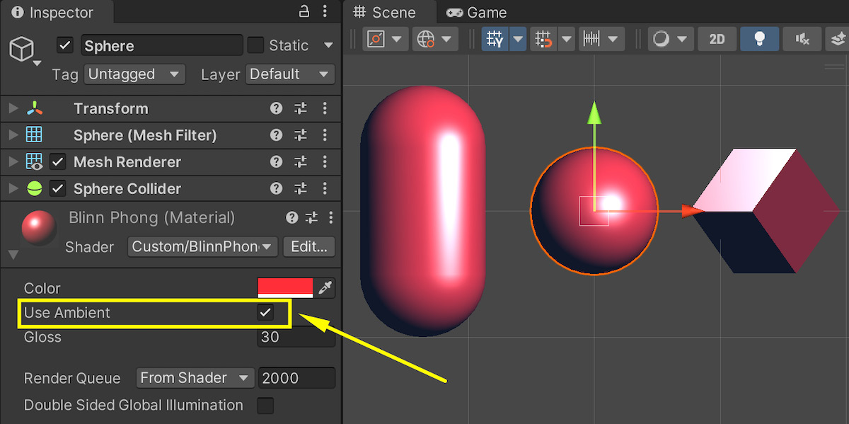
Figure 1.24 – Customized display of our float as an on/off toggle
This is already a nice improvement on our previous interface, but we can do more!
Improving our glossiness display
Another annoying part of our interface is that the _Gloss variable is currently a number that can range from one to the hundreds. Even worse, this large value range is non-linear – as the glossiness increases, you need to crank it higher and higher to actually see a difference. In many reference Unity materials, however, this setting is displayed as a linear slider that goes from 0 to 1, so how come our value doesn’t work this way?
The trick to getting this more intuitive display is to remap our _Gloss value to an exponential curve – this way, we can keep it in the [0, 1] range and keep the exponential behavior under wraps. For the user, glossiness will just be a normalized float that goes from a fixed low value of 0 (a very rough surface) to a fixed high value of 1 (a very mirror-like surface).
There are various ways of remapping the value, but often multiplying our input by a small coefficient and putting it in an exp2 function (meaning we compute 2 to the power of our input) gives a good result. We can also avoid the low values of glossiness that cause strange visual artifacts by artificially increasing our specular exponent value with a base minimum.
The exact formula, suggested by Freya Holmér in one of her videos (see https://www.youtube.com/watch?v=mL8U8tIiRRg&t=11892s) and wildly adopted since then, contains a few magic numbers that are not completely intuitive, but it works really well:
float specExponent = exp2(_Gloss * 8) + 2;
specularLight = pow(specularLight, specExponent) * _LightColor0.xyz;
With these modifications, our shader now works fine with a _Gloss value between 0 and 1. For the cherry on top, let’s actually convert our float to a slider with this range so that users directly know the minimum and maximum value they can use.
To do this, we simply have to change the type of our _Gloss property from Float to Range(0, 1):
_Gloss ("Gloss", Range(0, 1)) = 1
Unity will know that this property is a float that can only take its values in the [0, 1] range, and that should be displayed as a slider in the inspector. Figure 1.25 shows us the final result:
![Figure 1.25 – Customized display of our glossiness property as a slider in the [0, 1] range](https://static.packt-cdn.com/products/9781837636747/graphics/image/Figure_1.25_B19397.jpg)
Figure 1.25 – Customized display of our glossiness property as a slider in the [0, 1] range
Note that we could also use the same toggle or slider trick if we wanted to switch between the “plastic-like” and “metal-like” speculars. You could define another _Metalness float value in the [0,1] range, use it to tint the specular component and show it with one or the other type of display, depending on whether you want a continuous or discrete value.
These various modifications to our UI make it way more intuitive and quicker to use than our previous insanely diverse float values. We are now gently guiding the users to pick the proper settings and tweak our shader in a viable way.
A few additional tricks
To wrap up this focus on the customization of our property displays, here are some other interesting attributes that can help you improve your material inspectors:
[HideInInspector]: This attribute will hide the property that follows it in the inspector. This can be interesting if you are still in the development phase and want to keep some alternative property in your code for posterity without it polluting your inspector.[NoScaleOffset]: This attribute will remove the Tiling and Offset fields that appear by default next to texture slots in the inspector. This can be useful if your texture should be used as-is, and users should be prevented from changing its scale or its offset.[MainColor]and[MainTexture]: By default, Unity will consider that the property called_Coloris the main color, and the property called_MainTexis the main texture. Those are the values you will access in your C# scripts if you getMaterial.colororMaterial.mainTexture. The[MainColor]and[MainTexture]attributes let you define the properties that follow as the main color and the main texture in your material, even when they are not named_Colorand_MainTex.[Normal]: This attribute tells Unity that only normal maps are accepted for this texture property. If you try to use a texture asset that has not been marked as a normal map in its import settings into the slot matching this texture property, you will get a warning in the inspector, which can help with debugging.
With all these examples, we now have various techniques and tools for improving our material inspectors and making them clear to use for our users. We also know why it is important to devote time to these improvements and how even a simple UI such as our shader options here can be improved with some additional steps.
Summary
Over the course of this chapter, we have reviewed a famous shading model for 3D rendering: Blinn-Phong. We recalled the fundamentals of 3D lighting, and we saw how to compute and composite the components of a basic lighting model, the ambient/diffuse/specular model.
We then applied our theoretical study of the Blinn-Phong model in Unity to create our own Blinn-Phong shader with the built-in legacy pipeline.
Finally, we covered a few tricks and tools for improving our material inspectors so that users can easily tweak the settings of our shader.
You should now feel at ease with all the base concepts of writing shaders with Unity’s built-in render pipeline, applying them on objects, thanks to materials, and setting their properties in the inspector, which means that you are ready to dive into Unity’s new shading tools!
The next chapter will introduce us to this new world by exploring the other rendering pipelines Unity offers and explaining when they are useful and how to use them in your game projects.
Going further
If you’re curious about the basics of Unity shader coding (in particular, using the legacy pipeline and the Cg language) or about the Blinn-Phong model, here are a few interesting resources to check out or continue your journey from:
- Unity legacy shaders:
- Unity 5.x Shaders and Effects Cookbook, A. Zucconi (2016): https://www.packtpub.com/product/unity-5x-shaders-and-effects-cookbook/9781785285240
- Unity 2021 Shaders and Effects Cookbook - Fourth Edition, J. P. Doran (2021): https://www.packtpub.com/product/unity-2021-shaders-and-effects-cookbook-fourth-edition/9781839218620
- Writing shaders (official documentation), Unity: https://docs.unity3d.com/Manual/shader-writing.html
- Unofficial repository with Unity’s built-in shaders (per Unity version), TwoTailsGames (2017-2020): https://github.com/TwoTailsGames/Unity-Built-in-Shaders
- The Blinn-Phong model:
- Basic Lighting, J. de Vries (2014 –): https://learnopengl.com/Lighting/Basic-Lighting
- Advanced Lighting, J. de Vries (2014 –): https://learnopengl.com/Advanced-Lighting/Advanced-Lighting